11. Mechanical Design and Machine Build
For the next two weeks, we have to design and build a machine. Happy Spring Break?
Group Project Page
Here is the link to our group project page. This will show the entire overview and our final build, which actually works! Huzzah!!
Here you’ll find all my trials and tribulations involving the build itself.
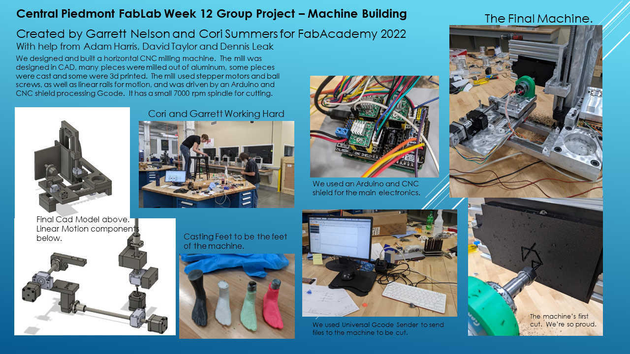
Slide is courtesy of Garrett, who did a fabulous job putting this together.
Ideas
We’ve been thinking about this week since the beginning of Fab Academy. We knew it would be difficult, but I didn’t have an idea of what to do. Denny suggested a cookie maker, I had an idea to make a lego sorter, and Garrett threw out a mini mill. After some back and forth, we decided to make the mini mill. The idea was to make something that we could use as a demonstration piece for the manufacturing students, and hopefully, something that they could use for simple projects, like engraving their names.
It also helped that Garrett had made one years ago and had some components we could use. This project would be different though in that it would be a horizontal mini mill as opposed to the more common vertical mill. All the milling machines we have at school are verticle. Horizontal mills are usually only found in production shops and are much more expensive and complicated in general than their vertical versions. We don’t have the space to have one for students to learn on, so having a miniture version to use to introduce to students would be extremely helpful in the long run.
Day One: Start with the Scraps
Garrett has done this before, which was already a huge help. It also meant that he had a ton of parts that we could potentially use for this project, and he brought them all in for us to sort through. However, after looking through the assortment, it turned out that there were only a few parts that we could actually use. He had multiple different ball screws, for example, but most of them were too long for what we want to make, or they’re the wrong diameter.
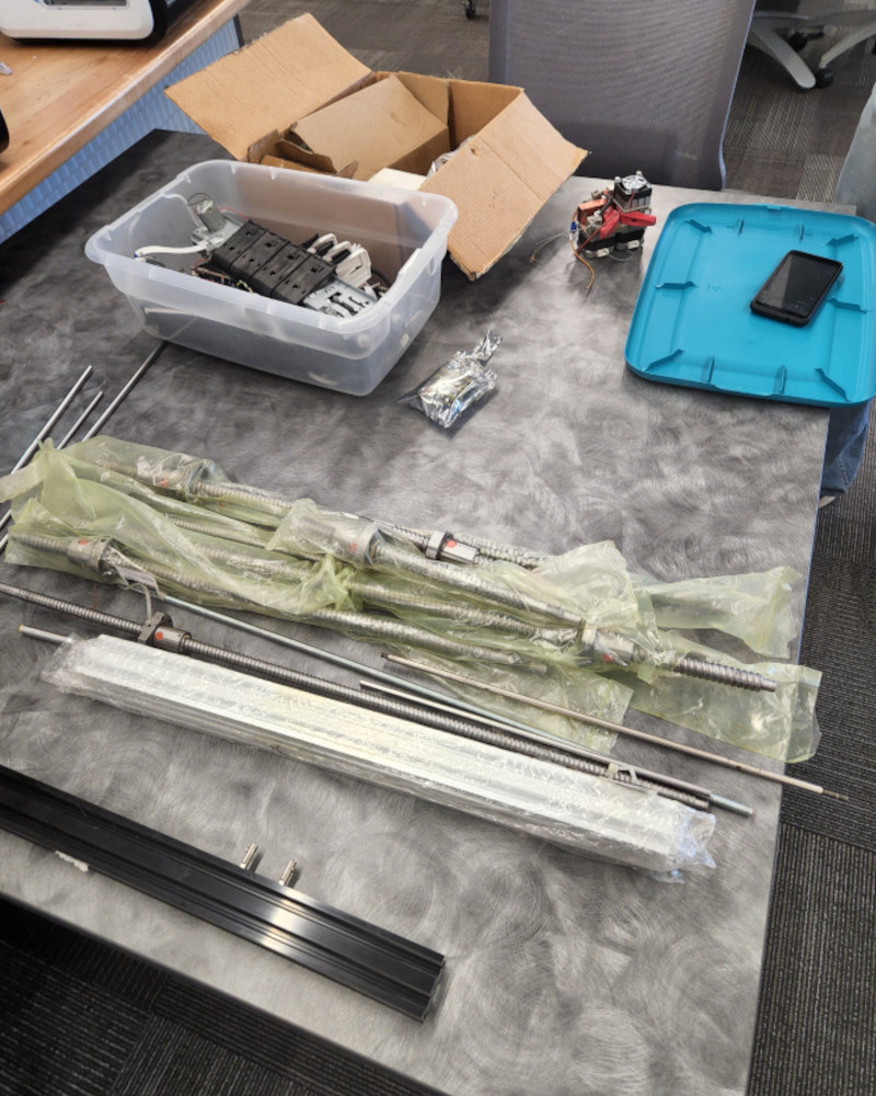
After grabbing what we could from the pile, Adam took us to a few different storage rooms in the building to see if we could find anything else of use. There were a lot of really interesting parts and pieces, a lot of older components, and even more things that I didn’t recognize, but again, not much for us to actually use. So that meant that we had to turn to Amazon for a lot of the parts. That’s not necessarily a bad thing, but we were more concerned about when they would arrive. Luckily, we managed to find parts with a reasonable delivery time.
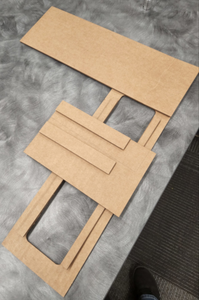
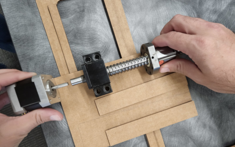
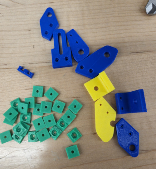
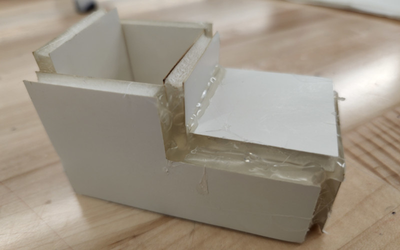
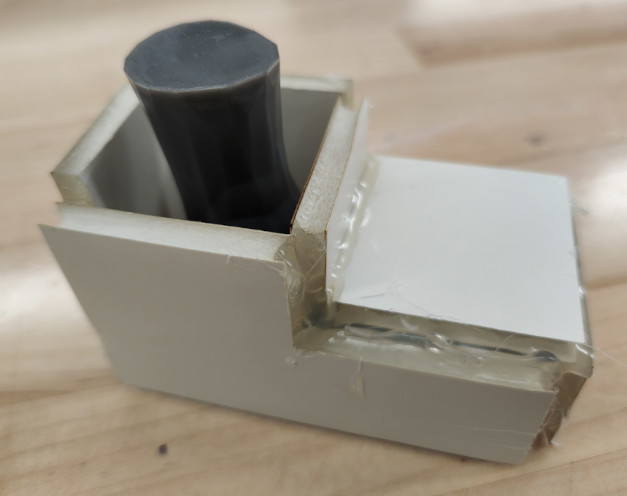
Next, we jumped into Fusion. Garrett had designed a lot of the mill already, so it was a matter of modifying the parts so they could be machined. While Garrett worked on that, I decided to laser cut some of the larger pieces so I could get a better idea of how big the project would be, and to do a rough idea of where components needed to sit. It’s much easier for me to figure out locations for parts and how pieces need assembled when I can move them around physically.
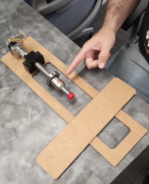
This eneded up being a bit of a test for me since I hadn’t used the laser cutter since the second week, but after a quick refresher with my site and Garrett’s, I was able to cut out some of the main parts for the mill.
This eneded up helping a lot, especially when we were trying to figure out how and where one of the servo would mount. The original plan was to have it on the top of the plate, but once we laid it out, it was clear it would be better underneath the plate.
That meant that we would need to add a riser, but it would give the table room to slide left to right on the rails. From there, we began mapping out mounting holes and how the parts would join together.
It’s really hard to design a bunch of parts to fit together. It’s even more difficult when all those parts need to move too. It’s even MORE difficult when a lot of those components aren’t available, so we had to do a Google search for a lot of them for the dimensions so we could model them in the full assembly. Some of the parts had multiple dimensions listed for the same thing, or the charts were blurry and hard to read.
In addition, there were a LOT of components to keep track of. Since there were so many parts, we decided to rename the components, and start each one according to what section they’re associated with. So everything related to the Z movement starts with “Z”, so on. The components can’t be resorted, so this was the easiest way to figure out which part was which.
We then decided to break it down into smaller pieces to refine, to figure out where the hole patterns need to be for the feet, the motor mount, ball screw holder, etc.
Day Two: In the Machine Shop
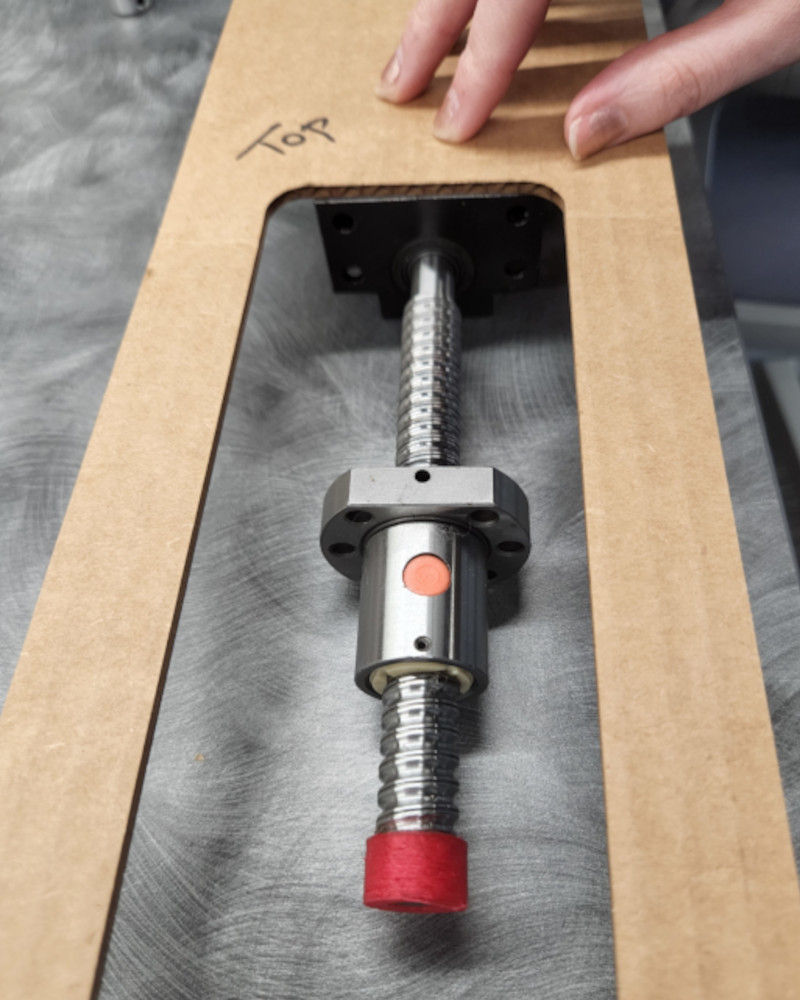
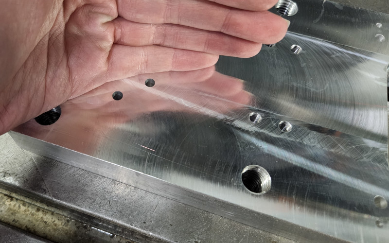
Garrett started machining some parts, so when I came in, I started working on tapping holes. The first thing we wanted to check was that the hole pattern was correct for the ball screw mount.
I tapped the M6 holes and did a test fit with the screws that I brought from work. Brought in some obsolete fasteners from work to use. They’re countersunk screws, but the heads fit really well on the mount.
Haas VF1
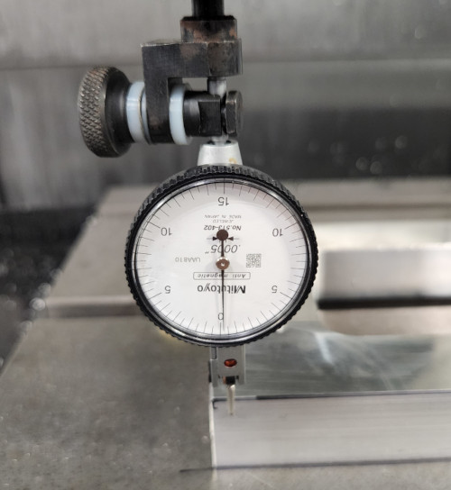
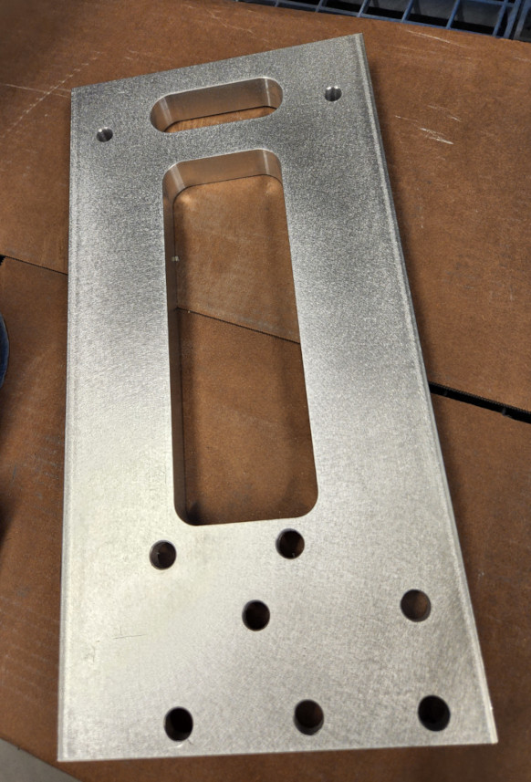
Next we needed to flatten the location for the rails, started facing, the side was not flat at all, decided to flip the stock and flatten the back face first so have a machined surface.
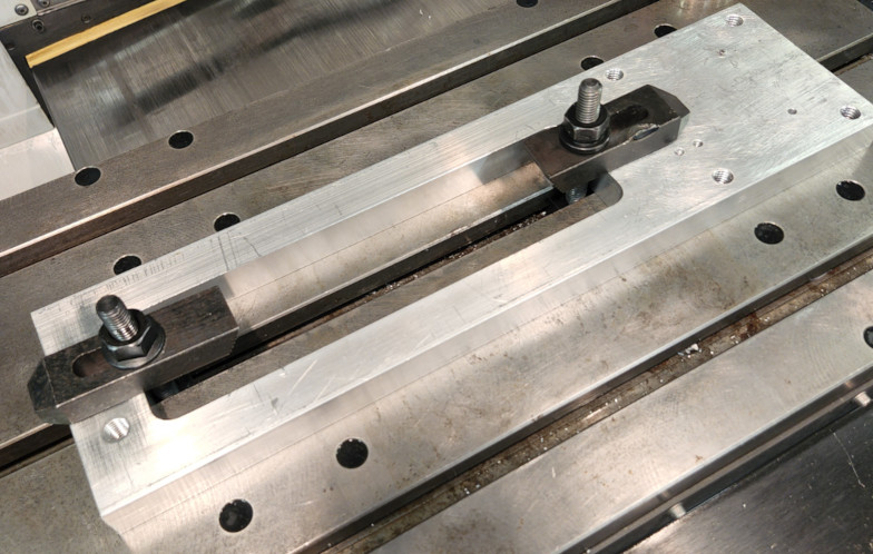
Then I was going to drill the holes for the rails on the original face. The plan immediately went sideways as I realized that the stock wasn’t flat at all. Even if I flattened the section for the rails, it would only be flat on one side, instead of the sides being parallell. That meant I had to flip the piece over and face the entire side, then flip it back over, face the rails, then drill the holes.
Since I had to machine the entire surface, I couldn’t have clamps on the top holding it down, but I had to secure the part somehow. This is where we got out the Mitee-Bites. These are low profile clamps that use a cam action to press the clamps into the sides of the part, locking it in place. They’re great to use and easy to set up.
I still went very easy when I faced the part. I didn’t want to scrap anything if I could help it.
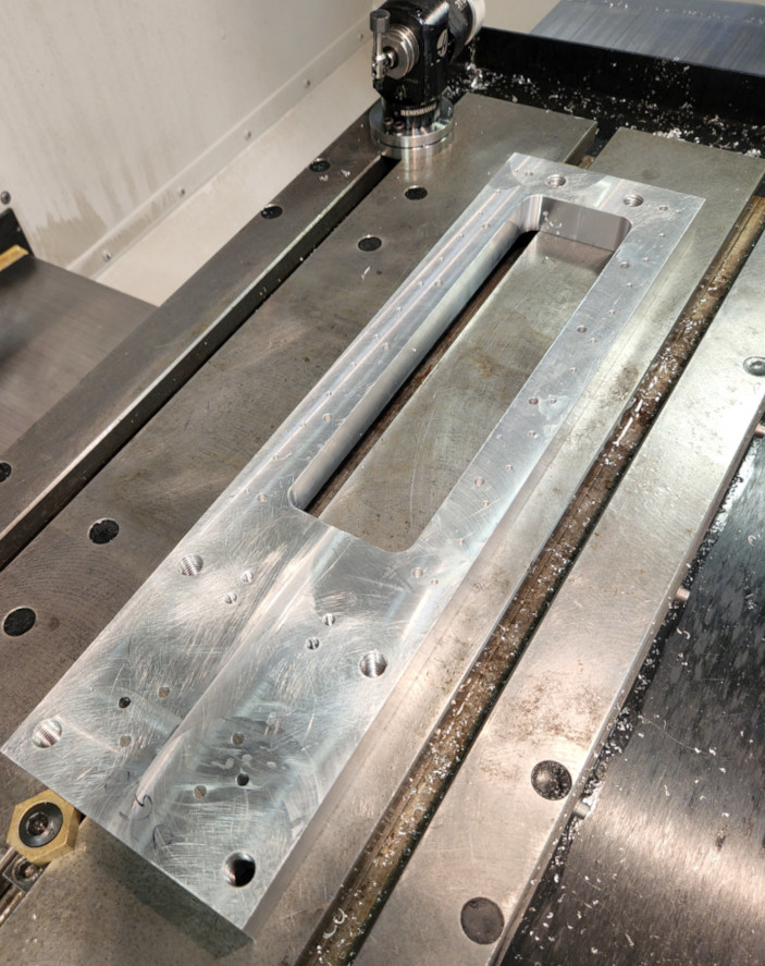
Now that the back was done, it was time to flip it back over and do the rails. I used the Mitee-Bites again just because I had them setup already, but I didn’t face the entire part. Garrett had broaken a tap in the part earlier, so part of it was protruding above the surface slightly. Enough that it would have destroyed the inserts on the face mill, so I avoided that section.
The other thing I did as I was setting up for this cut was align the part for drilling. If this was set up in a vise, then I could tram, or align, the vise to make sure it was parallel with the table. Since this is set up directly on the table, I had to use an indicator and run it along the side of the part to tram it in. That way when I run the program to drill the holes, they are also parallel with the part.
Once that was done, I faced the part and prepped for the next operation.
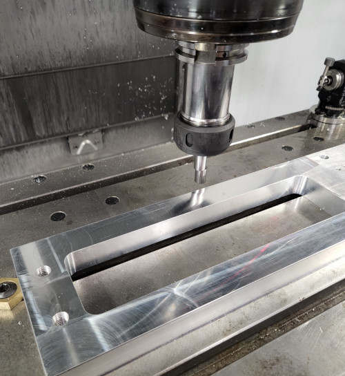
Again, I used an edge finder to locate the part, then I set up the machine for the program, touched off my tools, checked my offsets, and ran Garrett’s drilling program.
Day Three: Clean Up and Components
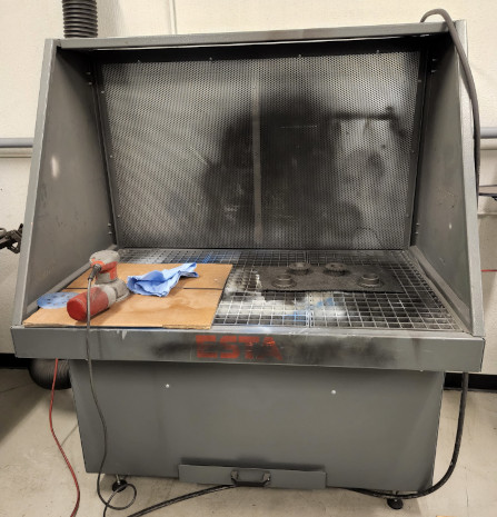
Sandblasting
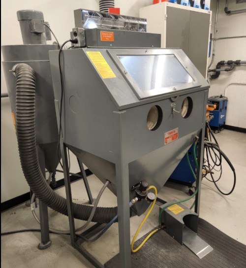
I took the parts we had made by this point with me so I could take them to work. There I have access to a sandblaster and some other equipment so I could clean up the parts and give them a nice surface finish.
We have two sandblasters, one for stainless steel and aluminum, the other for carbon steel. The one I used is a Trinco sandblasting cabinet, with a super fine sand as the medium. The nozzle carbide with a ¾” bore.
But before sandblasting, I had to clean it up a bit. First I used a chamfering tool to put a chamfer on all the holes. The quickest way to do this is to put it in a handheld drill, simple and easy. Then I used some sandpaper and went around all the edges to make sure they were all rounded and there weren’t any burrs or sharp corners. Then I took it to our welding room, which also has the sandblasters and a paint booth.
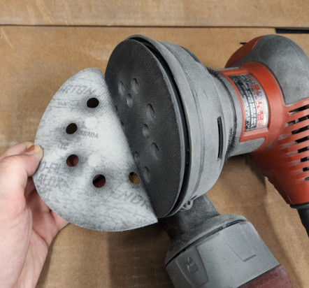
We have an orbital sander hooked up and ready to go when parts need a better surface finish but don’t need to be sand blasted. The sandpaper sticks to the sander with a fine velcro, and I’m using 80 grit, which is good enough.
The goal is to create an even surface that’s easy to sandblast. If the surface is consistent, then you spend less time focused on one location trying to remove a blemish or spot.
The sandblaster has two doors on it, one on the side and then a large one with the viewing window. We usually just open the top and load the part in. Then you turn on the air, located on the left under the cabinet, and flip it on, which is at the top on the left. Then you put your hands in the gloves, grab the part and the nozzle, and use the foot pedal to turn on the sandblasting.
The goal is to create an even surface finish. Sandblasting is a bit like using a pressure washer. It’s easy to create streaks or uneven lines if you’re not careful and consistent. The method I use is first to go over the whole surface slow and steady, mostly to get a “base coat” established. You can tell where the surface has been blasted because it leaves a matte finish behind. Then I’ll go back and even out any streaks, I do this by using the spray painting method, multiple light coats, holding the nozzle further away from the part to allow a wider spray. That way I don’t get any harsh streaks. Once I’m happy with the finish, I’ll flip it over and do the next side. One thing to remember is to get the edges. It’s easy to focus on the faces and forget that the edges need blasted as well. It’s especially obvious with fully machined parts since the surface is shiny versus matte.
Then I used the air gun to blow off any grit that may have settled in the pockets and corners and across the surface.
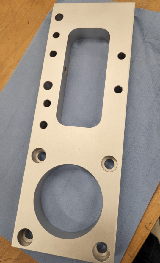
Once finished, I took it out and only used a paper towel to touch it. Sandblasting leaves a great finish, but it is easy to smudge it with fingerprints. If this happens though, we have denatured alcohol to wipe it down again.
Then it was just a matter of rinse and repeat with the other parts. The only difference was that I tapped the M6 holes on one of the plates.
Molding and Casting: Foot Edition
Since Garrett and I are now addicted to molding and casting, we’ll come up with any excuse to use it in a project. So we decided to make feet for the mill to sit on, or at least add a few for extra stability. The original idea was to make the standard round feet, like those found on the bottoms of chairs, but Garrett thought it would be funny to make them ACTUAL feet.
So of course we did that instead.
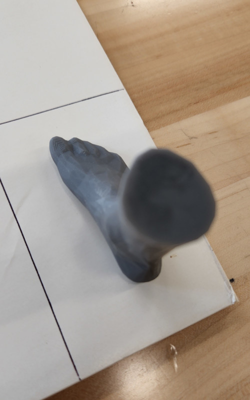
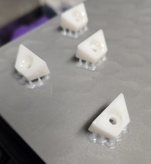
It’s surprisingly difficult to find a good model of a foot online. I eventually came across this model, the Sock Blocker on Thingiverse. The person who made it created it for his wife so she had a form for her knitted socks. Very clever; I’ll have to print one for my friend who also knits socks. In any case, the full model was the size of an actual foot, so it had to be scaled down a bit for our use.
Downloaded the file, was originally designed as a model for knitting, test fit handmade socks. So was a large model. Imported, needed to use autoscale to fit the bed, went down ot .65 or 65% of the original size, then scaled down even more from there. The foot needed to be big enough to fit a ½” bolt down in, but not too big that it is the wrong scale for the mill. Though not sure if it’s too small now, so we’ll just try and see. I tried to scale it so the ankle/leg of it will be wide enough for the head of the bolt to drop in when we cast it, more on that later.
Added supports so it was elevated off the print bed. Once it was set, I sent to the printer. It said it would take roughly 1 hour, 45 minutes to finish.
In our hunt for some other material, I came across some foam core board, so I decided to make a mold box from it. I tried to cut the pieces out with a blade, but the foam kept bunching up under the cardstock, so it would rip instead of cut. It looks really rough around the edges, but it’ll work. I then assembled the pieces using hot glue.
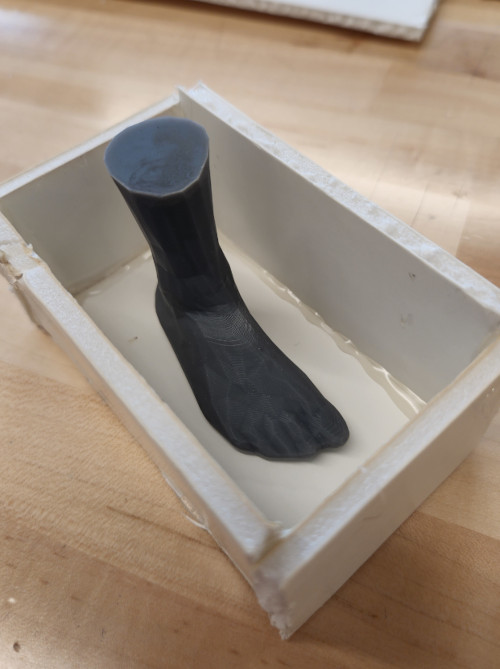
Then we had to figure out how to hold it above the bottom so the silicone could get around it, but we didn’t have a good way to mount it, so we used paper clips and lots of hot glue.
Again, looks awful, but it worked. We’ll need to figure out a better method in the future.
Once set, poured in the silicone and had to wiggle the foot around a bit. The silicone wanted to push the foot around so it was crooked. I wasn’t able to get it completely straight, which again, leads back to the way we had it mounted in the first place.
After we let it set, we had to pull the foot out. I’ll be honest, I wasn’t sure it was going to work, but after a little bit of wiggling around, I managed to get the foot out.
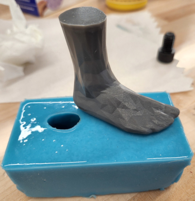
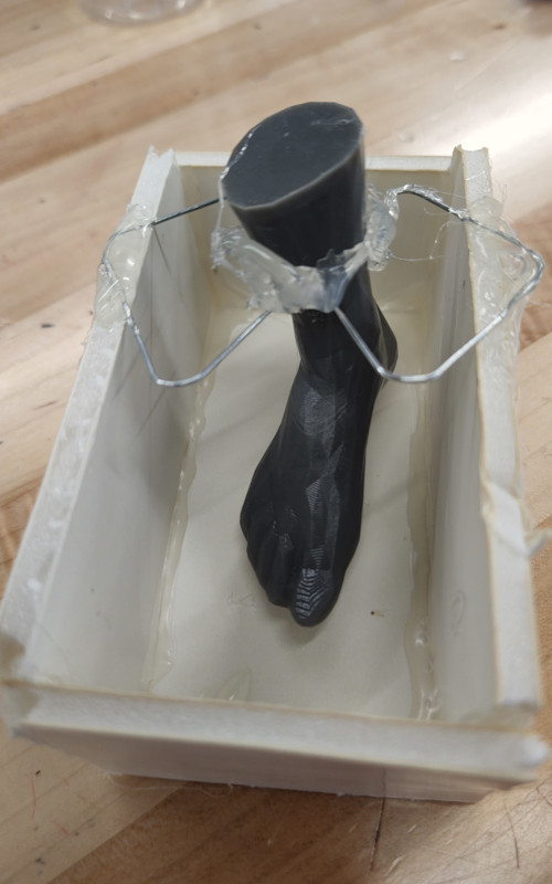
First thoughts, I need to design a better mold. It works, but we wasted a lot of material by pouring it as one solid piece. Since we’ll probably have to do this again, I’ll design a better box for it. In the meantime, we also realized that we hadn’t accounted for the “leg” of the foot, so there was no way to secure the bolt in the resin.
We created a “neck” using more foamcore and secured it with more hot glue, then poured another small batch of silicone. The hope was to create one solid mold, but the two pieces didn’t stick. We decided to run with it and poured the resin in anyway. We tried to seal up any potential leaks with even more hot glue, but silicone is just too good at what it does.
Nothing sticks to silicone.
The other issue became clear when we pulled the part out. The passage was too narrow for the bolt, so the resin collected on the top and bottom instead of fusing around it. The bolt pulled right off the foot the moment we tried to pull them out.
Lessons learned.
Day Four: The Big Push
This weekend was tough as the college was closed for the holiday. We weren’t permitted on campus on Friday and had to as for written permission to be on campus for Saturday. Fortunately we were able to get access, but losing a day put that much more pressure on us to finish. We were also at a disadvantage since one of our members decided to drop out of Fab Academy.
sigh
So yeah, we had a little mountain of things to climb.
Let’s Start With the Little Problems
During our mini meeting, we discovered a number of small problems and issues that needed to be addressed.
- Ball screw end oversized for the holder
- The connectors on the limit switches were too big to fit well on the board
- The servos need connectors added to them
- Multiple hole locations need tweaked
- The servo sits too high with the mounts, so either have to figure out a new mount so it’s aligned with the ball screw or shift the design to account for the additional height
- Limit switches need mounts designed, mark out locations for each
Calling the Calvary
Garrett had spent a ton of time machine Thursday night, but there were tons of little things that needed done. We started out by making a list of things to finish. At this point, we called in some calvary. My boyfriend, Ross, is a machinist as well, and he volunteered his services so we could focus on other parts of the build. When he arrived, we gave him the list of things to finish on the machining side and he got to work.
Huge huge shoutout to him for taking his entire Saturday to help us out!!
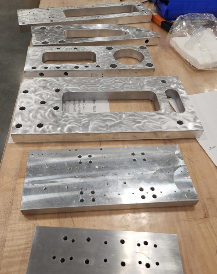
- Ran two programs on the Haas VF1
- One to drill holes for Z axis plate, to mount the aluminum extrusion
- Second added hole patterns to plate for additional mounting
- Drill and tapped holes on the sides of plates for mounts, done on the Sharp vertical manual mill
- Tapped any holes that needed done
- Trimmed the lengths of the linear rails
- Cut, machined, and tapped the aluminum extrusion for the Z axis plate
- Cleaned up any unfinished edges on the Z axis plate
- Cleaned up the surface finish on multiple parts
3D Printing List: Go Time
Then we had a list of items that we needed to 3D print either to test fit parts or to mount other hardware. These included:
- A spindle holder
- T Nuts
- Ball Nut housing for two axis
- Limit switch mounts
- Linear rail stops
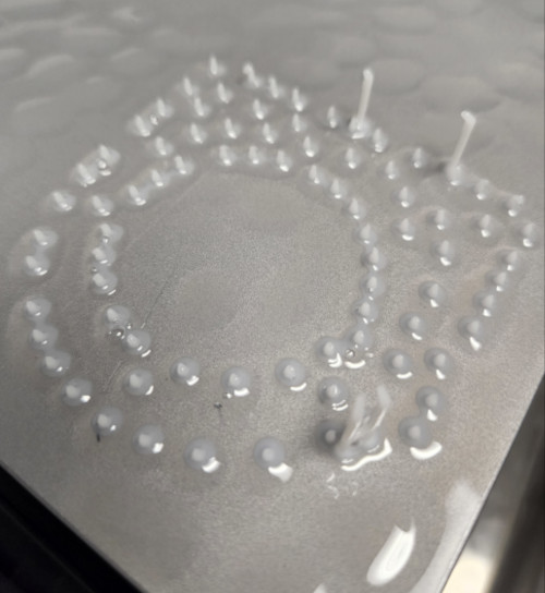
Found t nuts online on thingiverse, printed a bunch, in retrospect should have printed just one or two, but said it would fit our extrusion. Printed those, the many limit switch mounts Garrett had already designed, and a rail stop design, also found on thingiverse.
Test fit the t nuts, were too big, maybe due to elephants foot. Had to sand down the sides of one and even then was a tight fit. Also, the hole was too small for an M3, seemed more like it was supposed to be threaded rather than a clearance hole. The linear rail stop was also a failure. The design was too stiff to clip onto the rail in the first place, and it was too thick to fit in the slot if I even got it to fit over the rail at all.
Went back and designed my own t nut based on the model in Fusion, printed in a couple different orientations. Standing up was best as I didn’t need supports, the other orientations, the supports fused with the part. The part also fit expect where the elephants foot happened, but then we found a bag of regular t nuts to use.
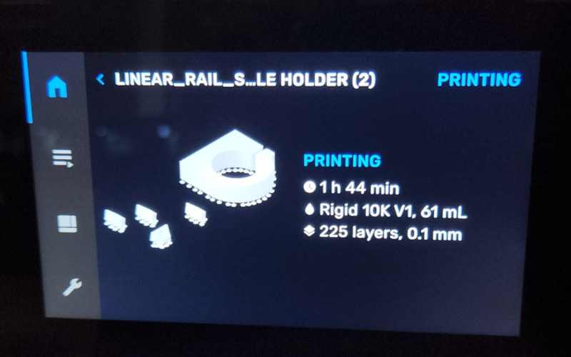
For the linear rail stop, the problem I was having was finding something that fit the larger rail , the MGN20. Most designs were for the MGN12 rails as they’re more common. I did find a universal rail stop that came Ina regular and low profile versions. The only thing was that they required one more hole at the end of the rails to mount each, but we simply added the hole with a drill and tapped the hole. Since these worked and will get a lot of wear and tear, we marked them to be printed in our new resin printer with the Rigid 10k resin. More on that later.
Mold and Casting: Zombie Foot Edition
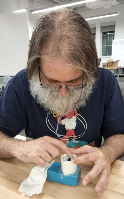
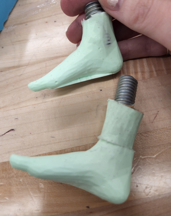
Next, I focused on fixing the foot. Garrett had ½” threaded rod to use, so didn’t have to worry about the larger head. Should fit better than the bolt.
First thing was to make a new mold that had the foot sitting straight so when we put the thread in, it’s as straight as possible. Given how hard it was to cut the board before, I decided to try to laser cut it. Michael had mentioned wanting to try it, so I looked it up. Found a couple links from Epilog’s own site, in their sample catalog, but it was mainly for plain foam. Should still work though.
Made some sime box shapes in Fusion but didn’t extrude them. Just need the sketch so I could export it as a DXF. I measured out the sizes I would need to enclose the foot but not have a lot of extra material like the first one. Kinda looked like a super simple boot.
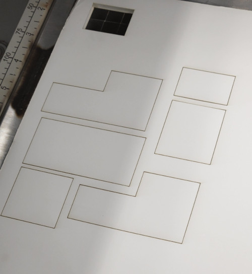
Cut the pieces with the laser cutter and seemed to do pretty well. Used speed 100%, power 60%, and frequency 50%. Did the trick for some, but had to cut twice for others. Mainly think is due to the board being bent slightly, but a second round without moving the board cut all the way through.
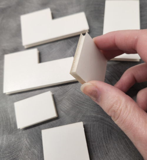
The pieces came out great, except I forgot to account for the thickness of the board. I could still use the pieces and filled in any gaps with the hot glue. I had to make one more piece to finish the boot.
Put that on and did a test fit. It was almost too small for the foot, I had to push it out slightly over the top part of the foot, but it fit really well overall. Time to cast.
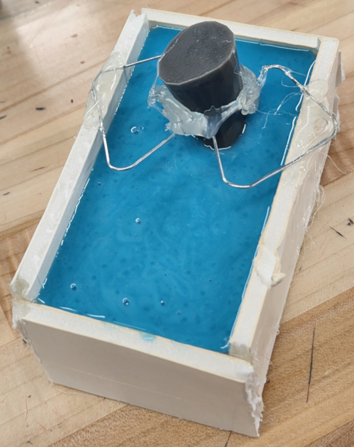
Gathered up all our supplies again and started to think about how to keep the height of the screw consistent. Decided to use the nut and screw the length until the end was flush with the top. That way it’s held the same amount above the part regardless of how long it is inside the resin, but that comes later. Mixed up the silicone and poured into the boot. Did a better job of estimating the amount needed for the mold, but the foot wanted to move around with the silicone as it was poured. Had to hold it in place until it settled.
While that set, I started setting up the resin printer. We have a new Formlabs BL3+ that is specifically for our general use. The others were bought for the Biomedical students, so it’s exciting to be able to use this one. When it was set up, they put Rigid 10k resin in it. One of the things with these printers is that all the parts that touch the resin have to be switched out any time the resin is changed. The tank and print bed is specific for that particular resin; it cannot be mixed with anything else. That’s why they include multiple labeling stickers, so all the parts remain together and marked appropriately. The big tanks include a really nice box for storage.
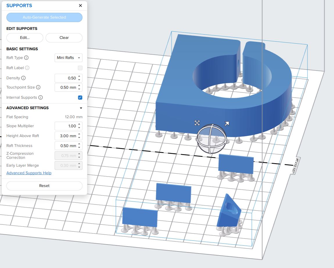
Set up the print with the Form slicer, added the linear rail stops, four total, and the spindle housing. Was quite simple to set up, same as the other times I’ve used the Formlabs slicer, just used a much larger print bed. Messed around with the settings a bit to cut down on the print time, mainly by reducing the raft size from a full raft to smaller individual rafts, then reducing the density of the supports to 50%. This put the total print time to around one hour and thirty minutes.
The printers are all connected via the network, so I just had to enter the IP address and send the print to the printer. Once sent, it went through its checks and warmups. The most interesting part was how it warmed the resin. The entire print tray has what looks like a roller that travels just under the bottom of the tray, under the film, that creates a wave effect in the resin. It then uses the wiper to mix the resin, moving from one side to the other. The warm up cycle took about 10 minutes to complete, then it began printing.
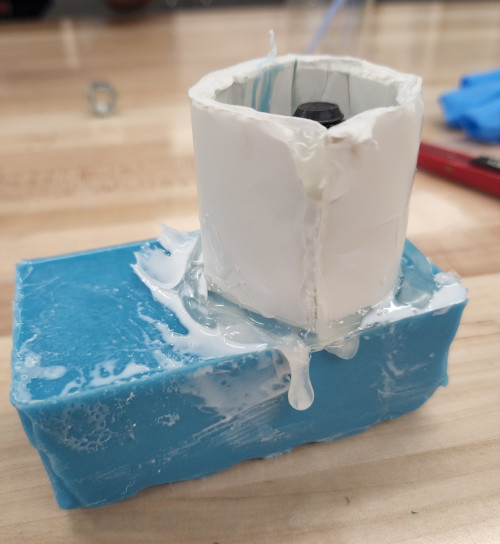
With the prints running, we then turned back to the finished cast. Pulled away the mold box and pulled the foot out. The mold was thin in spots, so we cut the sole of the food out.
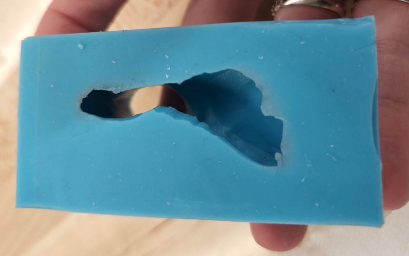
There was also a small hole in the crease at the top of the foot as well. Had to decide whether to remake the mold from scratch or try to make it work.
Didn’t really have time to cast an entirely new mold, so decided to make this one work and use the original mold as well. The original mold didn’t have a way to hold the nut above the cast resin well, so Garrett used a scrap piece of cardboard and cut a hole big enough for the screw to fit through, but the nut would sit on top. The goal was to embed the threaded rod in the foot so it can be screwed directly to the mini mill.
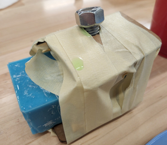
We noticed that the silicone created a bit of a seal on the table, based on the slight resistance it had when pulling it up, so decided to try to seal the bottom on a piece of metal and use hot glue to secure it into place. Had a piece of scrap aluminum, so polished the surface to create the best seal possible and added hot glue around the edges.
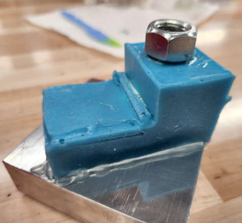
Then we pressed the two original mold pieces together and secured it with cardboard and an excessive amount of tape. Best case scenario, both molds work, hopefully at least one works, but both could totally fail.
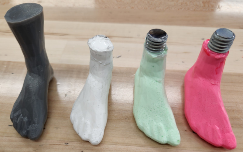
Decided to add coloring to the resin this time, and wanted to create a neon green color. Garrett found that if you add a bit of the yellow to the green pigment, it makes a much more neon green than using the green by itself. Was lighter color in the resin mix than we wanted, but when it cured,we actually got a minty green color instead. Most likely due to the resin curing white than clear.
Were pleasantly surprised to find that both molds held their seals quite well despite their flaws. Have high hopes for the results of both. Left them alone for about 15-20 mins. Found that even though the resin cures in about 10 minutes, the nearly fully enclosed molds cause the resin to take longer to cure. In an open container, like the cup, it cured very quickly. Before we could use the extra for another mold, the resin had already begun to set.
We set the molds aside and went back to the resin printer, as it finished just after we finished pouring and cleaning up the molds.
The linear rail stops finished, but unfortunately, the spindle housing failed completely.
Next, we popped the parts off for cleaning and curing, since the stations we have set up are for the smaller Form2 printer. The parts themselves came off easily, but the small rafts were difficult to scrape off the bed.
It seems that with this particular resin a large raft will be the easiest to remove, even though it uses a lot of resin and takes more time. The small rafts stick too well to the print bed and take a lot of time to clean up. We then double checked the cure times for the Rigid 10k resin. FormLabs recommends curing for 60 minutes at 70 degrees celsius.
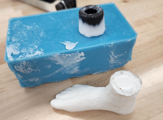
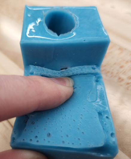
Once the parts had been cleaned and set in the curing station, we went back to casting to check the results. We were surprised to find just how well the sealing method worked for the second mold. There was barely any flashing, relatively speaking, and the hot glue barrier was almost not necessary.
The two part mold also sealed much better than expected, but when we took off the nut, it was obvious that the screw was very crooked, and probably unusable. I pulled both molds out, and neither required too much clean up, just removed the flashing from the smaller foot. The first mold also held up well, but the cardboard stuck to the resin along the top where it was supporting the nut.
Overall, we were both really happy with how they turned out. The coloring reminded us of a zombie’s foot, which gives us some ideas for later, but we decided to try another color. This time we went with red, and added a lot more pigment. The main issue is that the pigment didn’t mix very well in its container, so it was chunkier than the green and yellow and a bit more difficult to mix with the resin. We only poured it in the second, smaller mold and once again used the nut and threaded rod. Because of how the mold was poured, the nut was able to sit on top of the silicone without any additional support.
This mold seemed to take even longer to set than the previous pours. It’s possible that the amount of pigment added to the mix affects the curing time. Once we pulled this mold out, there were multiple spots of concentrated pigment. I was worried that the thicker portions of the pigment would be an issue, and it was clear in the results. Those spots were also stickier, like they needed more time to fully cure, or maybe that’s as cured as it would get.
Regardless, we had to clean up and head home for the day.
The Final Day
I got off to a rough start. I had to stay later at work, I had an appointment to make, then I sat in traffic as I tried to get to school. So I got there later than I wanted given how much still needed to be done.
First thing when I arrived, Garrett gave me a run down of all the things that still needed done.
- Motors needed hooked up and tested
- The boards we planned on using didn’t work, so had to find a replacement
- Initial connecting of electronics didn’t do anything, so need to double check power
- One more piece needed machined for the Z axis
- The parts that were finished needed cleaned up and reassembled
- Needed to create the video to show for tomorrow’s presentation
There was a lot to do.
Since electronics and programming is not my wheelhouse, I decided to take the machine apart and finish all of the pieces. As I disassembled everything, I made sure to keep the parts that we were using separate from the extras that were in the area as well. Hopefully that would make it easier to assemble later on.
The main issue was that I had sandblasted three parts, Ross had polished one, and the rest were a mix of machined surfaces and stock. I thought about sanding all of it, but I remembered that we had scotch bright pads for our air tools, so I decided to use those instead. It would be faster and leave a more consistent finish.
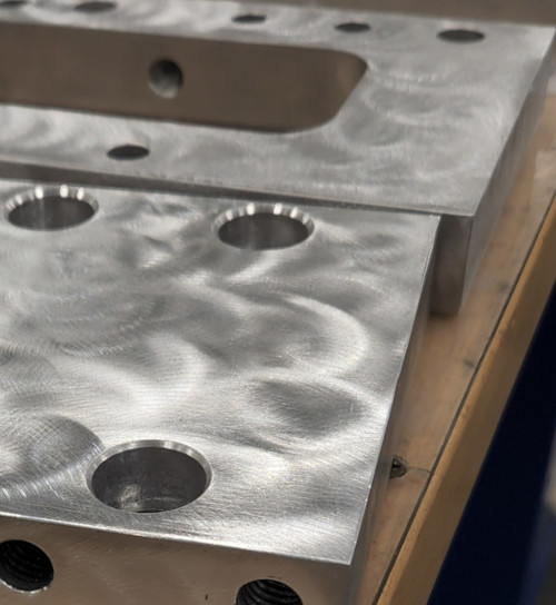
I was surprised to see the kind of finish it left when I worked on the first piece. I really liked the swirled pattern, so I ran with it. Garrett mentioned it looked a bit like engine turning, but obviously way more varied than the even rows and columns of the traditional method. The pattern also helped hide any imperfections on the surface, but most importantly, it allowed for easy cleaning.
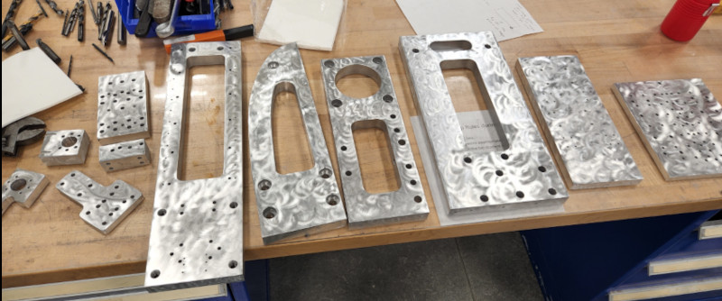
Sandblasted parts look amazing, but they’re especially susceptible to fingerprints and smudges. The same is true of polishing. The surface quality is fantastic, but you need gloves to keep the surface clean. With this method, we were able to handle the parts without worrying about getting the surface dirty, and then easily wipe them clean once we were finished.
Once I finished that up, it was time to reassemble everything. This was also when we set up the table to record some video of us assembling as well. While Garrett got all the electronics working, I cleaned up as best I could and set up my phone to record.
If we had had more time, I think we could have put together a really neat video with a series of time lapses showing the steps we took to create the mill. Unfortunately, things took longer than expected, per usual, and despite having some great footage, it would have taken too long to actually put it together.
After working on the assembling and finding more problems, such as bolts being the wrong lengths, screws missing for the new part, I had to call it a night just before midnight. Garrett and Adam stayed longer and were able to get everything put together and running. It was great to see the video of it taking a cut!
Final Results
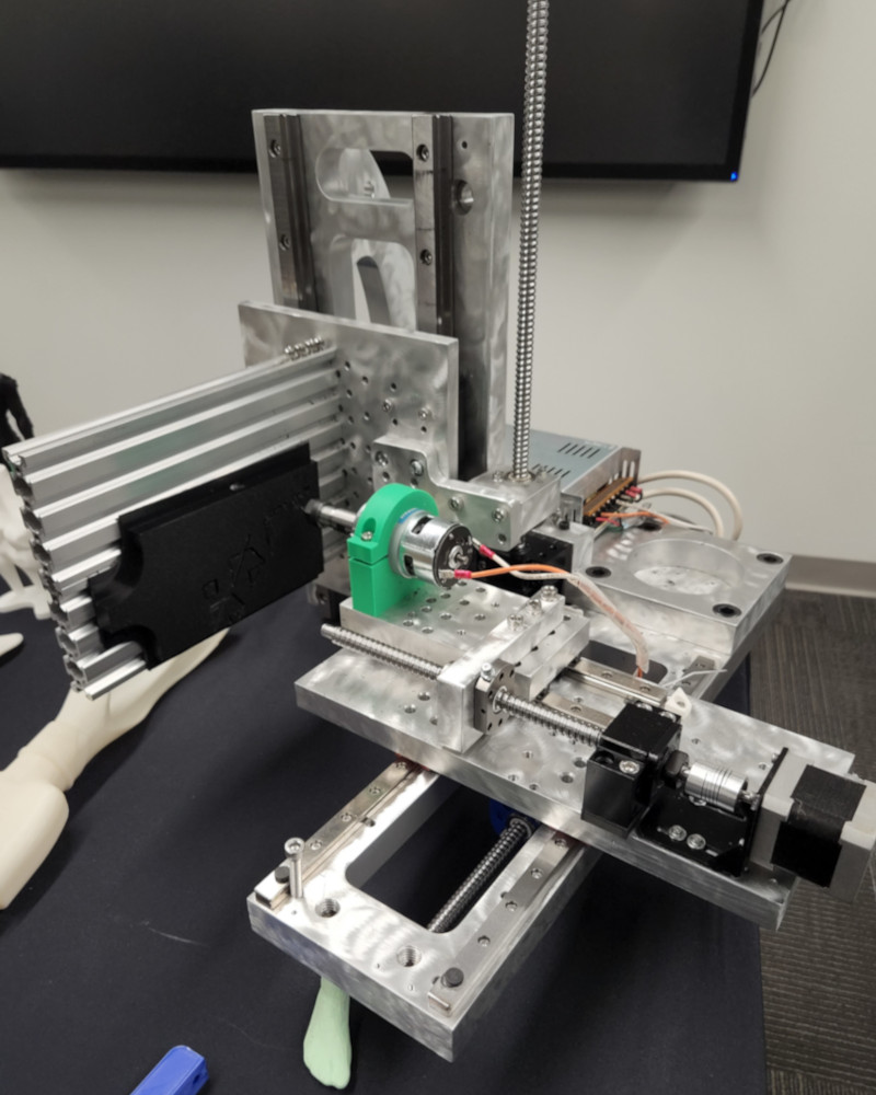
With heavy air quotes around “finished”. But it’s together and it works! We moved the monster from downstairs (the machine shop) to the Fab Lab so everyone could see it.
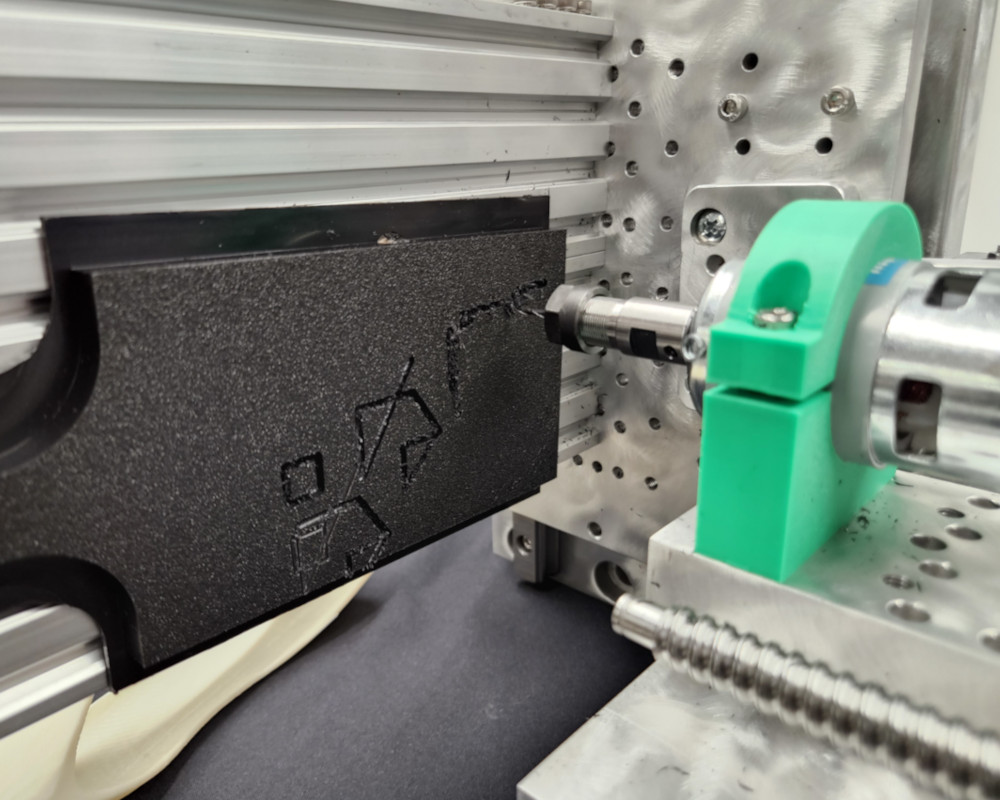
Look at that! It’s messy and sounds awful when it cuts, but it works, and that’s the important part.
Future Improvements
- A lot of the parts need to be remade. Extra holes, broken taps and drills, poor surface finishes
- Many of them need redesigned as well, to reduce the weight of the mill overall
- Replace the temporary linear rail stops with actual designed pieces
- Cable/wire management
- Replace the Z axis linear rails with a much lighter set. The Z axis in general is very heavy
- Properly align the linear rails to make it as smooth as possible
- Create workholding for the aluminum extrusion
- Design a 4th axis tombstone for multiple parts
- Potentially add a 5th axis later down the line
- Create a better “foot” for the base