3. Computer Controlled Cutting
This week, we get to start making things!! First we’ll use the laser cutter and the vinyl cutter.
This was the first week we had to be in the Fab Lab, and while I’m super extied we started making things, it also was a challenge to have enough time to do the things AND write about it too. I’m also starting a bit of a disadvantage as I have a trip the next week that will take up a majority of my time, so I’ll be behind on that too. I’ll update as I can, but it seems that a lot of what I’ve done so far is squeeze out 30 minutes of time here and there through the day to work.
Pictures will be added once I get back home!
Vinyl cutter
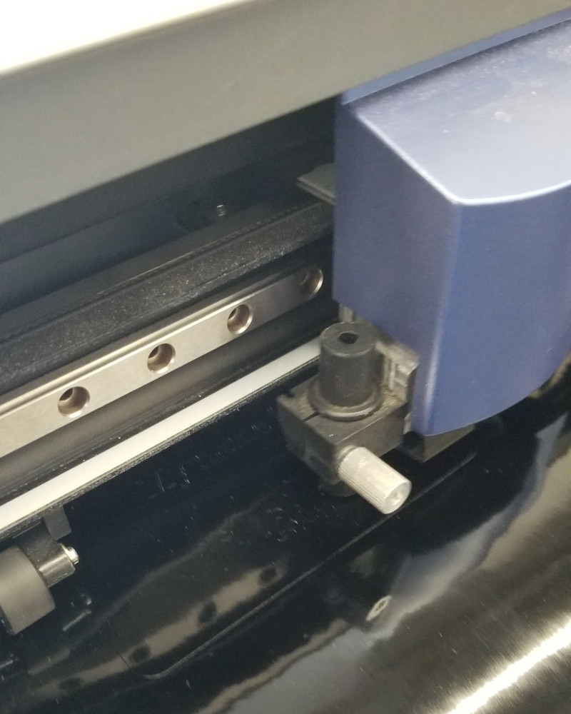
The cutter we have in the Fab Lab is a Roland GX-24.
I decided to use Inkscape since I had never used it before, and immediately loved it. The different settings are so much fun to play with, and it’s very easy to create random images and designs without needing any prior knowledge. The one thing I especially appreciated was the option to turn on dark mode from the start (I use dark mode for almost everything I have, I’m quite partial to it.).
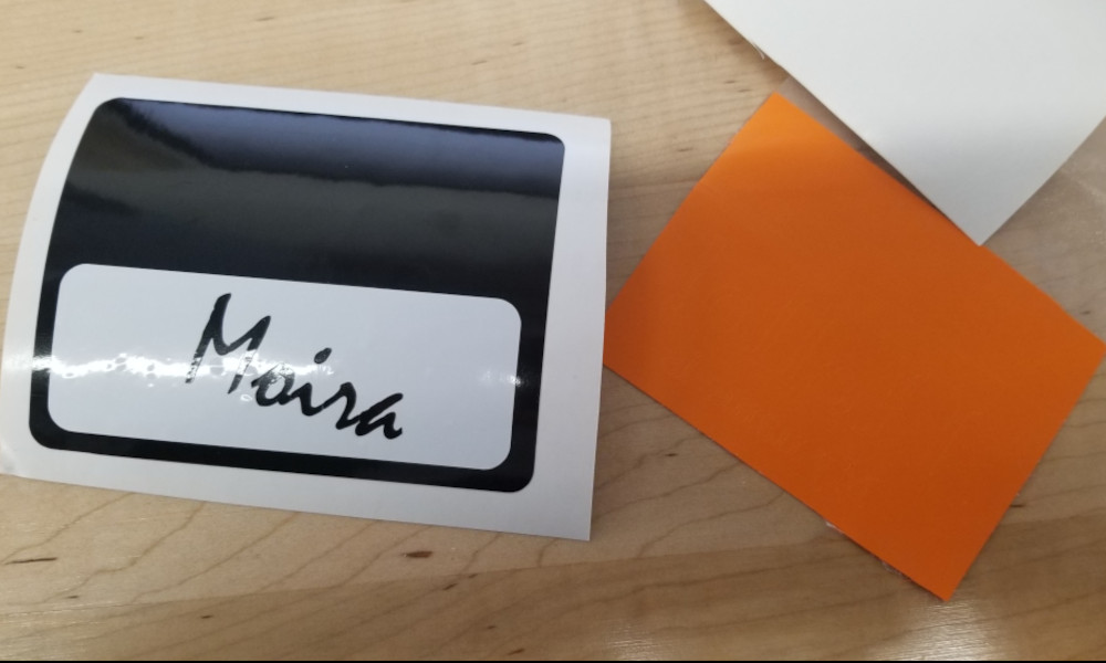
After playing around with it for a bit, I decided to get to work on my design. I want to make a sticker for my machine at work, which you can see in the picture on my “About Me” page. It is a DMU 75 monoBlock 5 axis CNC machine, and when she was installed, I named her Moira. Most people at work call her The Spaceship, but I would love to have a fun “Hello, my name is” sticker. I also want to make a sticker for another machine that will be installed next week, a Haas VF2. Her name will be Harriet.
I started with a new document, and since I wasn’t sure what size we had available for the vinyl sheets, I selected A4, or a standard sheet of paper.
Later I realized that the size was listed in the old tutorial that Adam sent to us, which is 24” wide by 12” high. Since our vinyl is on rolls, height doesn’t particularly matter, but would come into play anytime you want to use sheets.
It also helped to have some sort of scale visible on the screen while I worked so the sticker wouldn’t get too big. Then I looked up some images of the “Hello, my name is” stickers to get an idea of how I wanted the final design to look. Using the search as a guide, I used the rectangle tool to create the general shape and size, then used the text tool to write out the words. I created three separate text boxes since I wanted some variety, so “Hello” has its own box, “My name is” is another, and “Moira” is the last one.
At this point, split the file up into layers. I didn’t do this the first time and it made putting the design together more of a hassle than it should have been. Splitting it also allows you to decide which sections are which color, if using multiple, and plan ahead on what to cut together. This way you’re not switching out the colors multiple times when you find out one more feature needed to be the first color you cut. It’s also not a bad idea to draw out a rough sketch of the design and label which parts are which colors. You can use this when you move to assemble the pieces on a bigger work area if you don’t have immediate access to the computer.
The text tool was very easy to use, and had a great variety of fonts to pick from. I wanted a cursive font for the name, as though she had written it herself, so I picked a font that was also easy to read. I also wanted it to be slightly tilted, instead of being straight across. I clicked on the text box, which then brought up the arrows to adjust the size in different directions, but then clicked again (found completely by accident), and the arrows changed to show ways to rotate the box.
Insert Font pictures
This seems obvious, but some fonts will cut better than others, and size matters a lot. The blade can cut very fine details, but it will also catch on the recently cut raised edges. Assuming that the text cuts well from start to finish, then you have to take into account how much weeding will need done between the letters and how small those pieces will be. It can get very tedious very quickly.
After messing around with the arrangement, I wanted to round the corners of the white name box, but I had to do some digging, including a Google search, to find the tool. In the top menu, under “Path”, select “Path Effects”, which brings up a sidebar. Then select the item you want to modify, in this case the rectangle, and click the “+” button at the bottom of the sidebar. I was surprised at how many options there were! But once selected, I played around with the numbers until I had the desired look. After looking at it a bit longer, I added the effect to the background as well.
Insert Path pictures
Once I was happy with the design, I had to change the line weights. This is what the machine actually cuts along. First, I selected my design, then went to the top menu under “Object” and selected “Fill and Stroke”. The same sidebar will appear as before, this time with three tabs across the top. Under fill, select the X or “No paint”. If you had color in your design, it will disappear, but that’s alright. The color was only for reference as the vinyl cutter can’t see it. Under the next tab, stroke, select the first box past the X, or “Flat Color”. Now the lines should be black. Last, in the final tab, set the width to 0.001”. The vinyl cutter will follow this line when making the cuts.
I use dark mode almost exclusively, and the design disappears into the background at this point. It’s still there, but the lines are now very thin. It may be worth changing background at this step to make it easier to see where everything is in case you need to move parts of the design around.
Recently Inkscape added another option under Stroke Styles called “Hairline”. It sets the width of the line automatically, but because it is a slightly wider line, the cutter will follow both sides of the line. This creates a really interesting pinstriping effect that I’d love to experiment with, but it’s awful to use with text, especially if it’s not very big.
Once all the settings have been selected, save your file as a PDF in addition to the standard SVG, then move to the computer hooked up to the cutter. We have one computer that is used exclusively for the vinyl cutter. Open the PDF on the computer and select “Print”. The printer is called “Roland-GX 24”. Set the design to “Actual Size” and check the preview. Then click on “Properties” across the top, and set the page size. Since I used the A4 letter size to make my design, I put in those dimensions, but this area needs to be big enough to include everything that you want to print.
Actual Cutting!!
Phew, that was all the setup. Now we can get to the really fun part: cut and assembly!
Before we go any further on the computer, we need to make sure the cutter is ready and set up properly. To load the roll, set it on the rollers and make sure it comes off the roll over the top, like toilet paper, and slide the edge through the slot. Once visible on the other side, line up the edges with the white blocks and move the small rollers so they are pressing on both corners of the vinyl. The rollers must be inside the white blocks, but you can slide the vinyl itself side to side until everything lines up. Once set, push the lever on the back right side up until it locks.
Turn the cutter on, and select the type of sheet that is loaded. Roll was the first option on the screen, so there’s no need to change anything. Press and hold enter to confirm. The cutter will move from one side to the other to confirm the size of the roll. Next, we need to run a test to make sure the cutting force is correct for our vinyl.
This should be done every time a different roll is loaded. The material may be the same, but the thickness may vary slightly, and some colors require more pressure than others. I found that the black vinyl cuts well with 140, but the gold vinyl required 150 to cut cleanly.
To run the test, move to a location off to the side, away from where we’re going to cut, and press and hold test button. It will cut a small square and a circle. If the cutting pressure is correct, the circle should peel up easily without lifting the square too. If not, some adjustments are needed.
Press the “Force” button on the control, hit the left or right arrow to select, then scroll up or down to increase or decrease force. Press “Enter” to select, then press and hold “Menu” to exit. Run the test again with the new settings.
Next, align the cutter on the vinyl
Align edge of roll with the bottom left corner of print
Set the origin by pressing and holding the “Origin” button when you have moved the cutter to your starting position, then hit “Print” on the computer.
This awakened the crafty side…
When you want to print another file on the same roll, move to the next position and set the origin again. This is very important, as it will move to whatever the last origin location was. If you forget, then it could cut the new pattern right over your last cut.
Remember where to press and hold button, where to change settings, how to get out of menu
Move roll forward and cut off cut section
Remove any excess pieces BEFORE using transfer tape
Cut a small piece of the tape, enough to cover what you want to move Don’t remove the backing until ready to put it together.
Change out the rolls and repeat
Notes on Vinyl Cutter
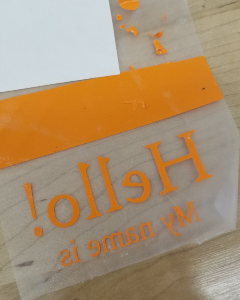
It is much easier to weed BEFORE putting on the transfer paper
Draw and map out the design FIRST. Figure out what sections need to be which colors, and then group them together in Inkscape. You can also write a quick cheat sheet to keep track, by making a rough sketch of the finished product and labeling each piece. This save a ton of time and material, as one, you’re not switching between rolls when you forget to cut something, and two, you don’t cut something on the wrong color and can’t use it.
Hairline creates a line that gets cut on both sides, creating a little gap. Is a pretty cool concept with a lot of potential for large pieces, like to create a pin striping effect, but is awful for text and lettering If the letters are too small, then the vinyl will catch on the blade as it’s trying to make another close cut
The cutter starts at the bottom left corner of the pdf, set the origin in this location, so bottom corner is close to edge of the material to try to minimize waste
Material management - need a set place to put everything together, get a better workspace location
Dark mode - I use dark mode every chance I get, but it makes it difficult to see the design when adjusting the line weights. The default color is, of course, black, which disappears very quickly on the gray and black checkerboard pattern. I will need to experiment with it to see if I can change the line color to white if I’m going to keep using dark mode.
Final Thoughts
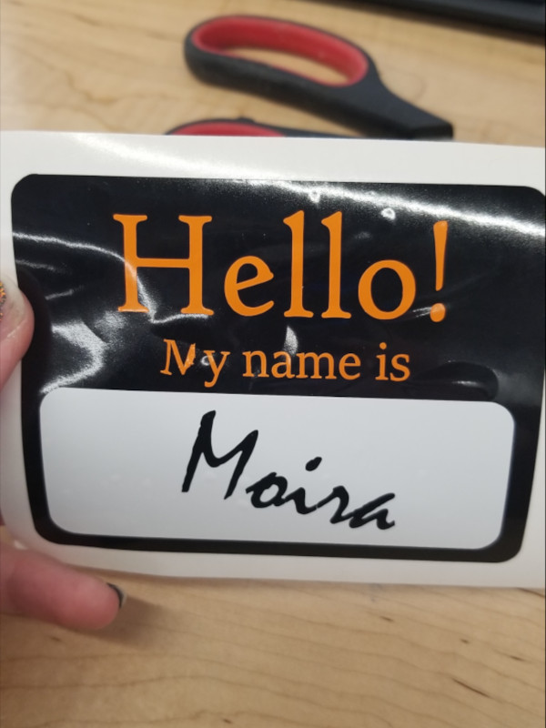
The “M” didn’t play nice when I tried to get transfer the font. It didn’t cut very well initially, but I thought I could save it, but overall, still very happy with how it turned out.
I have absolutely fallen in love with Inkscape. It’s super easy to use, has tons of features and settings to play around with, and answers are easy to find with a quick Google search. I’ve seen lots of people use vinyl cutters for their own projects, and have always wanted to learn, but have not had the opportunity to or availability of a cutter to mess around. I will be making a point to use this frequently in the future.
Laser Engraver
We have two Epison FusionPro 32 laser cutters, and each one is connected to one computer. We used the left laser cutter for our tests. They also require a key to use, which Adam keeps on hand to prevent people from using them without supervision.
Garret created the files for testing in Inkscape, which made it very easy to print to the laser cutter. Simply select “Print” from the menu and select “Epison Fusion”. From there, the main screen popped up, with the options for varying the settings for the laser cutter as well as a camera that showed the printer bed. This made it very easy to line up the file against the cardboard we had inside. The file itself consisted of two squares, one with just an outline, and the other with a gradient, and a circle with a gradient. The first square tested the power levels for cutting, while the gradients tested engraving.
Before hitting “Print”, there are a couple settings that need to be turned on and/or active. First is to set the “Auto Focus” to “Plunger”. Second, the actual cutting area needs to be adjusted to cover the entire location that needs to be cut or engraved.Otherwise, the laser will stop at the edges of the boundary even if the file has more things to engrave and/or cut.
To test the Vector, we kept the speed and frequency the same, and adjusted the power in increments of five (the first few are in increments of ten before we changed it). The first three tests each cut really well, but at 35, there were some places that did not cut all the way through.
We tested Engraving at the same time, keeping the resolution and speed the same and again only adjusting the power. In this case, the first few tests were too strong, and the darkest portions of the gradient burned through the top layer of cardboard. Engraving required much lower power than vector overall, as 15 power seemed to give the best result. We also tested a few different dithering modes, using 15 power, which gave very different results against the standard dithering.
Parametric Explained
First thing to note: Parametric design. A parameter is basically a variable or function that other dimensions are based on. When the parameter is changed, the feartures based off it change as well. This makes it easy to adjust drawings and models without having to go back and change every single feature, or fix things that may break with a change.
In Fusion, parameters are called functions. Every dimension is assigned a number, shown as “dx” or “d11”, “d12”, so on and so forth. If you want to use one of the dimensions as the controlling parameter, you can either select the dimension or type it in. In that case, instead of a number being displayed, the dimension will show “fx=dx”, or function equals the selected dimension. We’ll use “d11” as an example, so “fx=d11”.
It’s also possible to create simple equations with the dimension. For example, “d11-5”. If “d11” equals 10, then 10-5 is 5. If it equals 12, then it equals 7.
In my design, I decided to make the extursion amount, in this case 5mm, the parametric variable all other dimensions are based off. When I change the thickness of the part, then the slots on the side will also change and update.
Making the Construction Kit
I had a hard time coming up with a design, and I finally settled on a basic triangular shape with a few additional features. I decided to use Fusion 360 as I’m familiar with the function option, used for parametric design.
First, I created a new sketch, then used the “Polygon’‘ option under “Create”, and chose to use the “Circumscribed Polygon”, which means it uses an inner circle to determine the size of the polygon, instead of the outside points. I selected the origin as the center, three sides for a triangle, and made it 50 mm in diameter. Then I created a construction line that was 10mm from the corner, and created a line perpendicular to it, cutting off the corner. Then I applied a fillet to each side that had a 5mm radius.
Next, I wanted to apply this to each corner, so I used the “Circular Pattern” option under “Create”. I selected the line and two fillets, the origin as my point of rotation, and how many instances it needed, in this case, three, and hit enter. Now each corner has the same features without having to create each one separately. Then I finished the sketch.
Then I extruded the part, making note of the name of the dimension for future reference. Since this determines the thickness of the part, this is what will change when we change materials, so this will be our controlling dimension.
Setting Up and Cutting
Since I used Fusion 360 to create my shapes, I had to convert the file to something Inkscape can use. From Fusion, save the file as a “.dxf”.
Open the file in Inkscape. When importing the file, the default unit of measurement is millimeter, so the conversion is set to 1. If the file was created using Imperial, the conversion needs to be set at 25.4. Once opened, I had to set the page size.
Highlight the whole work, then go to “File”, then “Document Properties”, and adjust the page size to the working area, found about halfway down the page.
Then move to center the work in the new area. Change the line weight to no background fille, set the line color to “Red” to cut, and then the stroke style width to “0.1 px”. Save the file as a “.svg”, then it’s time to print.
I used the computer hooked up to the left laser printer, and from here I was able to select the printer from the list. Unfortunately, this is where I ran into a problem. The computer did not recognize the laser cutter, and needed to be hooked up again. Garrett found the IP address of the cutter in the settings on the laser itself, and I followed the prompts on the screen to reconnect it. I entered the IP address when prompted, and everything worked without an issue. From what I understand, this is something that happens on occasion, and just needs to be reconnected.
I had to close the printing window, but when I tried to print again, it recognized the printer and was able to see everything. I changed the probe to “Plunger”, then moved the file onto the cardboard via the camera in the laser cutter. The camera is especially nice for aligning the file and seeing exactly where it will cut. It’s also nice when something has been cut, to line the next file as close as possible to minimize waste.
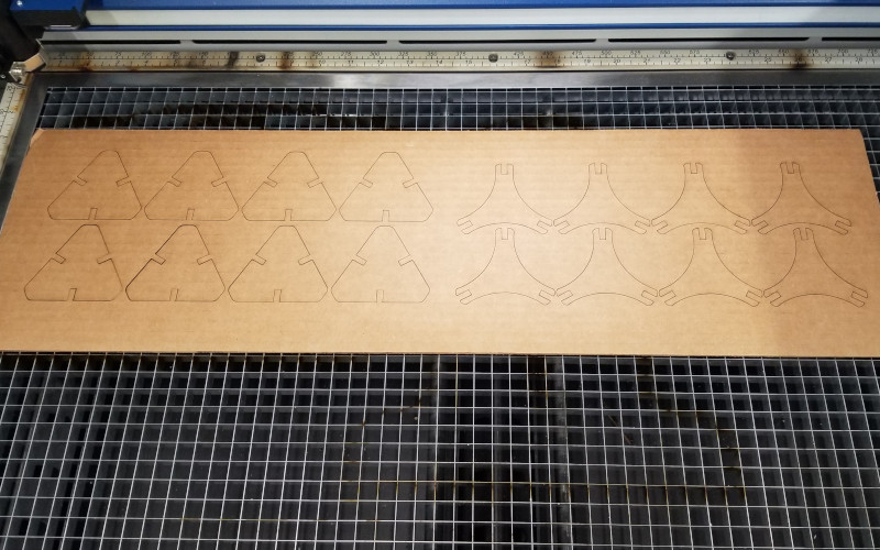
The cardboard we used was long enough that I could cut both of my shapes from the same piece. After cutting the first file, I did the same process and lined up the second file.
Results
The files came out fantastic! The lines were very clean and the shapes came out easily.
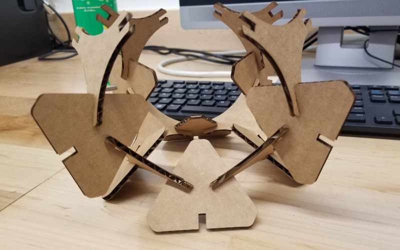
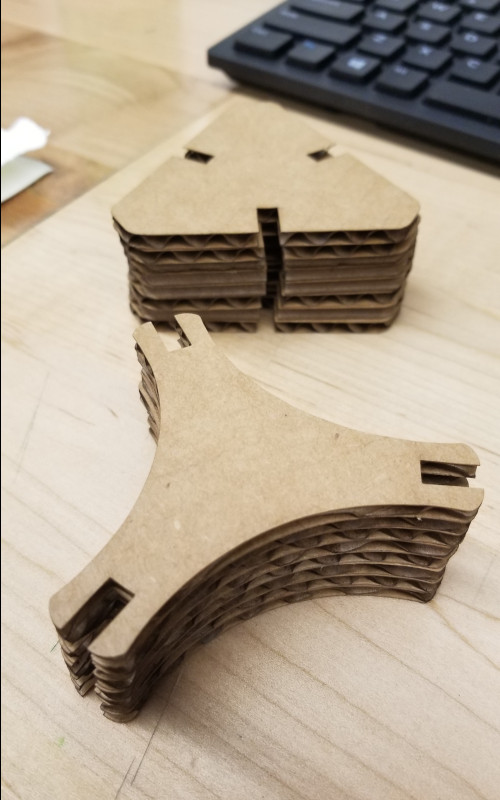
However, I’ll have to cut the pieces again; the slots were too big. I ran out of time, so I’ll have to cut everything again, but it will be much easier to do it again later. Overall, I had a ton of fun with the laser cutter and learned a lot about its use and settings. I can’t wait to try it again with different material.
Group Project - Laser Cutter Characterization
Garrett really took the lead on this and had a lot of the tests designed and ready to go, and I’ve very grateful that he took the time to do so.
For the group project, we had to characterize the laser cutter by conducting a series of tests and experiments to find the best settings for different materials.
He also walked us through how to use the lasers and set up our files to cut. After I got the hang of it, I helped with the tests on the cardboard, which included testing the vector and engraving settings, as well as a few of the dithering options. I then labeled everything on the cardboard so we could keep track against our charts.
Unfortunately due to time, I was not able to help when they began running tests on the birch plywood, but once the others made the information available, I wrote up the section on engraving for the group.
Once finished, we weren’t able to upload it to the group site as we still needed permissions set up, so Garrett hosted on the write-up on his site, which is found here.
Files
Below are the links for the files for the contstruction kit, made with Fusion 360:
The files for the laser cutter are found here.
The files for the vinyl cutter are below. I did two different stickers, one for this and one for fun!
References
How to round the corners of rectangles
How to make a gear on Inkscape