4. Electronics Production
This week we created a PCB, including milling, soldering, and programming.
I’m on vacation this week, so I’ll be playing catch up for now! (as of Feb 17-21)
First Things First: What is a PCB?
As someone who knows next to nothing about electronics and their components, this week was the first time when I was really worried about finishing and actually grasping the concept. As luck would have it, it was also the week when I had a trip planned, so I started out behind.
Adam was kind enough to come in the weekend before and let me practice my soldering skills on an Arduino board, and he went over the CNC machine that we would use to mill the boards. I had a touch of experience with soldering through work, but it’s been a few years. Lucky for me, after taking ages to put the board together, it worked! However, that was also when he told us (Garrett came in as well) that we would be doing surface mount soldering, which is a whole different level. Level one soldering to Level five. Can do.
So this leads me to the first question of this week: What is PCB?
PCB stands for printed circuit board. It is the board that is used to program other boards that are hooked up to it. The name is a bit misleading as we’re not printing it, but will be machining the features directly on the board.
Setup - Round One (Total Bust)
Immediately out the gate, I wasn’t sure where to start. Adam had sent us all the information we needed, but it felt like I had been handed a jumbled stack of files and told to put them in some logical order.
I read through the instructions, but again, it feels like they start in the middle of the process. The first step is to download certain files, but the extensions don’t match what was written, and the extensions that are there are unfamiliar, so I’m not sure where to start.
I started out by downloading a few of the PNG files from Adam’s Fab11C repo. I wasn’t sure if these were the correct files, but I figured I could play around with a couple and see what happened. Then I opened mods. I’m glad I had a guide; I’ve never used this before and it’s not quite intuitive, despite what some people have said.
I followed the instructions in Adam’s video, and used the Fab11C-F_Cu.png.png file. So far, it looks right.
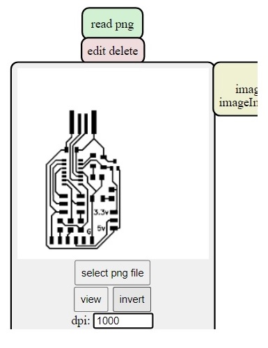
Turns out I inverted it when I didn’t need to.
Whoops…
That looks better.
Next step was to start using the machine, except I couldn’t get the computer to recognize the printer. I tried a variety of things, but given that the Roland only has a power button, there weren’t a lot of options. The light was on, the door was shut, and the spindle and table went home. I even looked through the user manual to make sure I wasn’t missing anything.
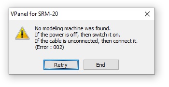
sigh
I’m very tired. I’m sure I’m missing something simple, but I have so many other questions, I need someone else here who knows what they’re doing. I’ll pick this up later.
I’m so glad I saw Nick, the Fab Lab assistant. I spoke with him about my problem connecting with the machine, and he mentioned that if another person is logged into the connected computer and has the program running, then a second user cannot access VPanel. Because a couple other people had used the machine before me, most likely one of them forgot to close the program before they signed off. He mentioned the issue to Adam, and now everyone should be aware to close the program when they’re finished. The second attempt let me on without any issues!
Setup - Round Two (Success!)
Okay, gonna try this again.
Adam sent us a link to his site with some tutorials he created on how to set up and use the machine, which are extremely helpful.
Armed with some new knowledge and a better idea of what to do, I tried everything again. I started from scratch since it would be easier to make sure I had all the correct files and steps. The most important thing I figured out what that all I needed was the .png files that were the traces and the outline of the board. I just needed the pictures of what I was going to mill. I’ll have those specific files listed at the end.
First I opened up mods. Right click anywhere on the screen, then select “Programs”, “Open server program”, then scroll down to your machine. In this case, it’s under “Roland”, then “SRM-20”, and I selected “PCB png”. This brings up the webbing to create the file the Roland needs to cut the board. A lot of stuff populates on the screen, but you only need to worry about a few of them.
In the first panel, click open and select the .png file with the traces. A preview appears in the box along with the size of the file. Make sure this is set to 1000 dpi, or at least close. It should populate with 999.998, roughly. This is also where we can invert the file so it cuts the correct areas.
In the next panel there are two options. Click “1/64 traces”. This is going to calculate the toolpath to outline the traces on the board using a 1/64th 2 flute endmill. Nothing changes in this panel, so we’ll go to the next one.
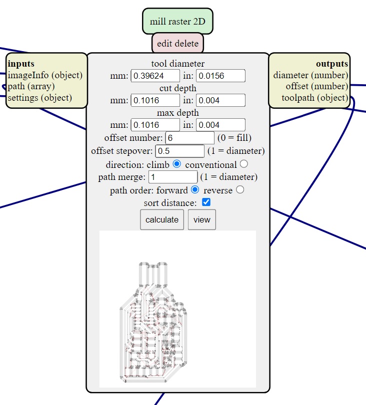
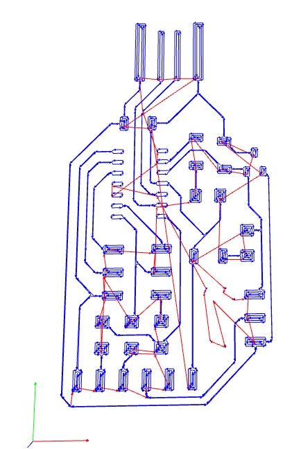
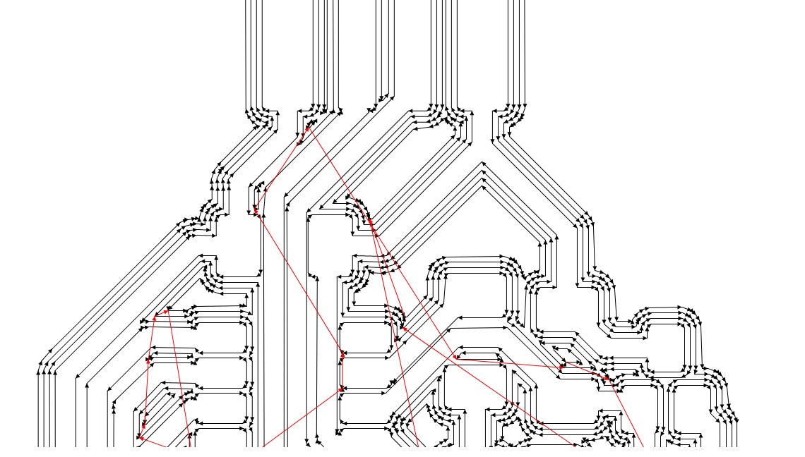
This panel generates the toolpath, shown in lines the tool will follow to cut the board. Almost everything here is left alone, except we changed the “offset” to six instead of four. This confused me at first because I didn’t know what it was referring to or why we needed to change it, but the confusion was in the terminology (explained below).
The next panel is actually in the bottom left of the screen, if you follow the path. This is where you set up the parameters for the machine. This is another panel that needs to have the terminology corrected, specifically the “speed” option at the very top (again, explained below). The important thing to remember on this panel is the origin. This is the starting point for the tool. I changed the X and Y axis to 0 as well as Z.
The default for Z is 10mm, which means it will start milling 10mm above the zero point . Physically, the tool will follow the toolpath above the surface, without cutting anything, if this is left alone. Useful when you want to do a test run, just to make sure the pathing won’t do anything drastic, but annoying if you’re trying to make a cut. If you notice the tool moving up and around in the air when trying to cut, check this value first.
Last step is to delete the path branching from this panel and replace it with a save option. Click “Delete” in the red box under “WebSocket Device”. I right clicked, selected “Modules” then “open server module”, then scrolled down until I saw “File”, and selected “save”. To connect the panel, I clicked on the yellow input box, the the matching yellow output box on the milling machine panel.
Milling the Board
The CNC milling machine is a Roland, and is set up in the soldering lab on the fourth floor. Adam sent us a link to his site with some tutorials he created on how to set up and use the machine, which are extremely helpful.
In the machine shop at work, we have a rule, one that is taught immediately from day one: clean your area, up to and including your machine. It’s so ingrained at this point that I have to have a clean machine at the beginning of my workday. Otherwise, I have to clean it before I can do any work, and this is no exception.
After cleaning up the work area, I removed the used material and set up a new sheet. I lined the back with double sided tape and aligned the front left corner of the material with the sacrificial piece on the machine.
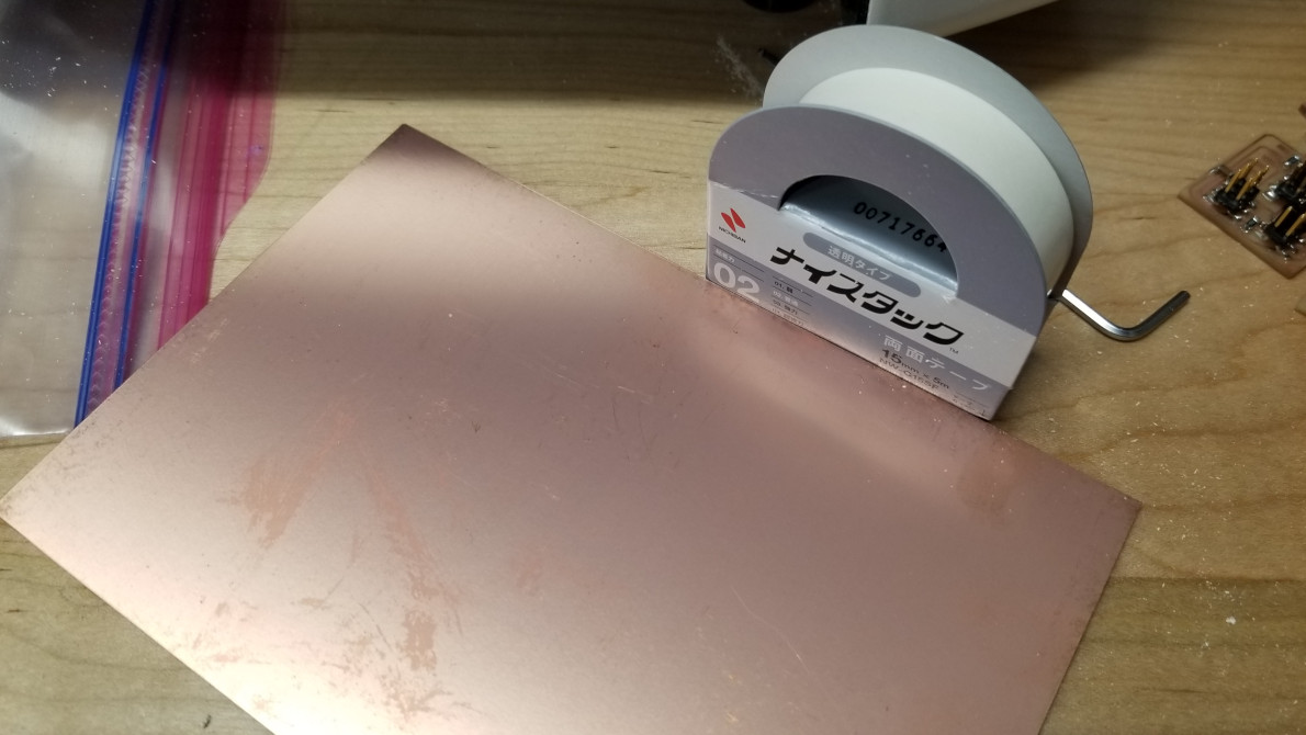
This particualar brand of tape kept the PCB in place the best. I put three strips across the back, which held it perfectly.
At this point, I watched Adam’s specific video on how to mill using the Roland.
First step is to load the tool. The endmill we used to mill the traces is a 1/64th two flute endmill.
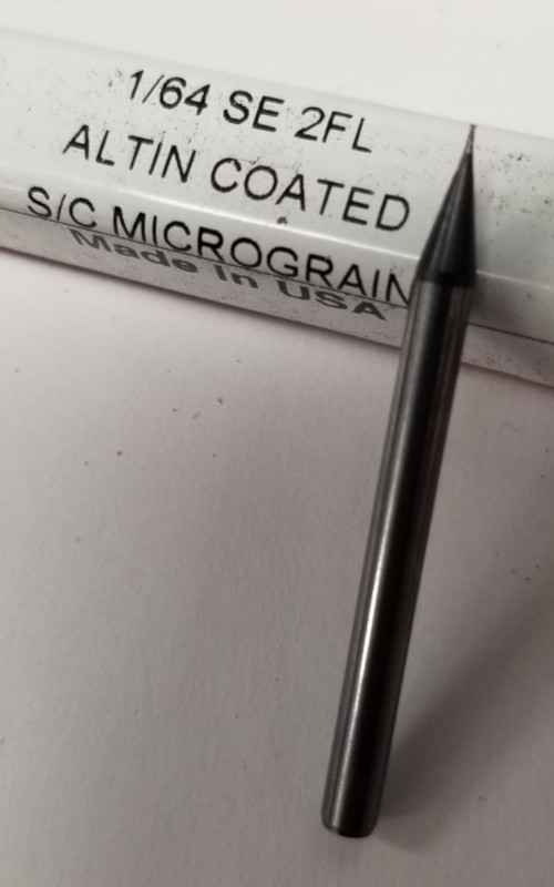
This is the smallest endill I’ve ever used.
Because it is so small, it must be handled carefully so it doesn’t break before being put into the spindle. I loosened the set screw and slid the tool inside. It was a bit awkward to reach and hold the tool; there’s not much room to maneuver and the gantry in the Z axis doesn’t come up very far. Once set, I tightened the set screw again, just enough that it was snug against the tool, or until the allen wrench stops moving.
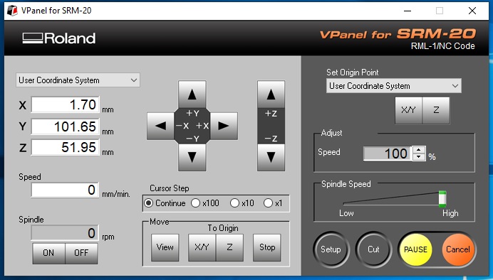
The control panel as seen on the computer.
I moved the tool in the X and Y axis until the tool tip was in the front left corner. Then I lowered the tool in Z until it was just above the material (BE CAREFUL HERE, the machine wants to move very quickly and in set increments so it’s very easy to go too far and smash the tool into the plate). Then I loosened set screw and lowered the tool onto the plate and let it rest there, then tightened the screw. The tool is now at Z zero (Z0.).
6 - on the control screen, click setup make sure parameters are correct
7 - then click cut, select any files that are listed and delete them, to make sure you don’t mix up the files, then open the correct file that was created using mods
8 - Once double check all is correct, click initiate, will immediately start cutting.
A Few Notes: Terminology
1 - I get the appeal of mods. It’s essentially plug and play, and takes care of the converting and creation of files. However, because we’re using a small CNC machine, the terminology should accurately reflect this.
Offset- What this really means is step over, or the number of times the tool shifts to make the next cut once it completes one pass around the toolpath. In this case, the number of step overs was set to six, so the tool will make six passes, stepping over slightly with each pass to cut a little more material until it reaches the final dimensions.
Why does this matter? In machining, offset refers to the information about the tool itself. For example, the tool offset tells the machine the length and diameter of a specific tool. Then the program looks for that offset, and uses it to calculate how far the tool needs to move for each step over. In addition, a work offset tells the machine where a part is located. The program then references this offset to know where to move to make the cuts. In cases where only one part is made at a time, only one work offset is used, but when there are multiple setups inside the machine at once, multiple offsets are used as well. Each offset can be assigned a different setup, allowing for a part to undergo multiple operations, which then leads to finished parts coming off the machine with each cycle. It’s used primarily in production and job shops with large part quantity orders.
Speed - Speed means RPM, or revolutions per minute. This is how fast the spindle is rotating. In this case, mods uses it to refer to mm/sec (millimeters per second), but what it should say is “feed” or “feed rate”. Feed rate is how quickly the tool is fed into the material, or how quickly it moves through the material. We dropped this down to 3 mm/sec since there aren’t very many other factors we can control on the Roland.
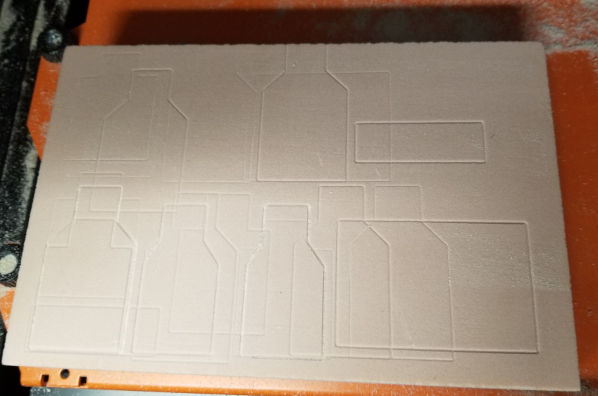
Results
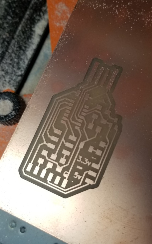
This is just with the traces cut, but the final board looked great too!
The board looks great!!
Surface Mounting Soldering: Joy (But it Actually Was?)
Can I start by pointing out how awful the terminology is for this step? Stuff? Really? It sounds like I should be shoving a bunch of components in a bag. It’s good to know that terrible terminology isn’t limited to the machining world.
The only soldering I had done up to this point was the standard through hole setup. Line the component up, put the wires/legs through the hole, bend on the other side to hold it in place, then apply solder. Easy. Kind of.
Surface mount soldering it very different, starting with board itself. All the pads, the silver squares or circles, are on one surface. There are no holes; everything it applied right on top. Which means that the components themselves are also different. Resistors are a perfect example. I’m used to seeing the small round components with a wire sticking out at each end. You then bend the wires 90 degrees to poke them through the holes, then seat it as close and flush to the board as possible. Once soldered into place, the excess wires are trimmed, leaving a nice point that looks similar to a Hershey Kiss. Instead, the resistors for surface mount are tiny rectangles with their ends wrapped in a tiny strip of metal. They sit completely flat on the board and are secured with a small puddle of solder on either end.
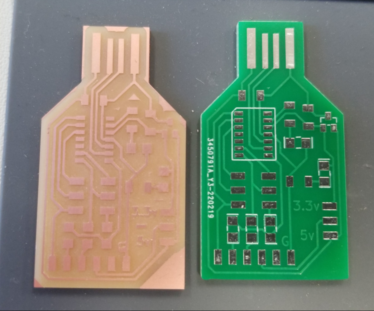
As an experiment, Garrett decided to order PCBs from a company to compare how they looked versus our milled versions. Spoiler: They looked great. The quality was amazing, at least it seemed like it to me, and it was also nice to have a practice board to work on before I tried to solder my own board.
Before doing that, Adam had a large blinky board he would give students to practice surface mount soldering, so I got to work trying my hand at putting it together. The back of the board had pads of various sizes, from 1206, the size we’re using for our boards, all the way down to the, quite frankly, impossible 402. I focused on the 1206, and when I felt comfortable, I started on the front. Because there were so many LEDs, it helped reinforce checking the direction before soldering them. Garrett pointed out how to tell the correct direction, which is marked by a green stripe on the cathode side. The easiest way to remember the direction is that the LED is always pointed alphabetically, meaning the anode is first, then the cathode which points to the ground.
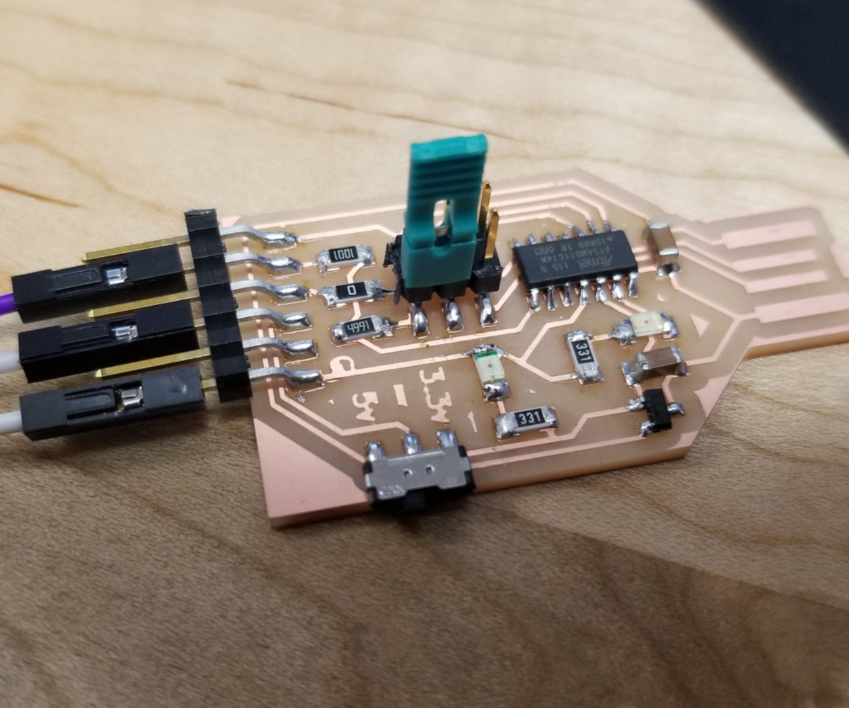
After putting about half of it together, I moved on to the manufactured programmer. I soldered all the components and gave it a look. Not too bad, if I do say so myself.
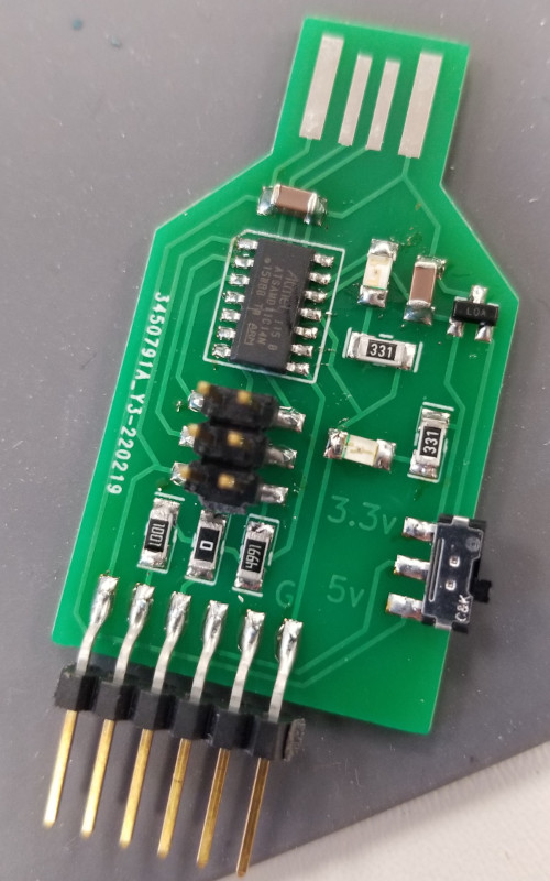
We then used this board to check my connections and to set up the program, which I’ll go into more detail below.
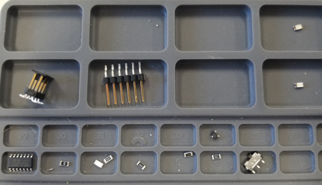
Time for the real thing. I decided to use both a green and red LED, so I kept them separate.
Insert the table of components here
Then I moved on to the actual machined board, and immediately I could tell the difference between the manufactured solder pads and the copper. Copper does not heat as quickly, so it took a bit more patience. Garrett suggested that I could use the traces between the pads to pull the solder and to transfer heat, as long as it doesn’t touch another component and create a bridge. Those are bad.
It took me a long time to solder the board. I went slowly to make sure I didn’t mess anything up. It would have been fine, I could just mill another board, but I also didn’t have much time. In the end, slow and steady worked in my favor.
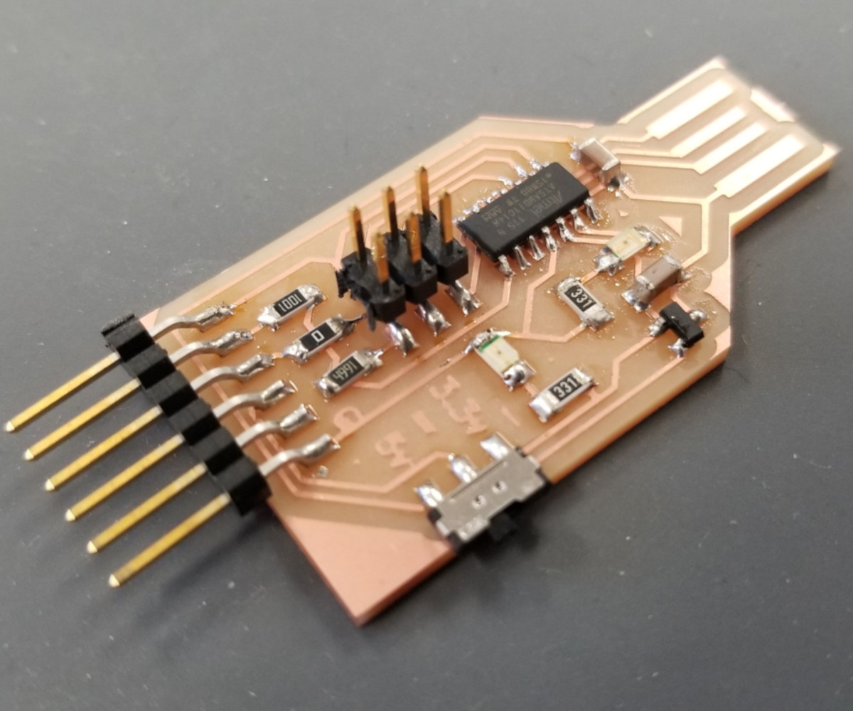
I’m so happy with how it turned out! I really enjoy soldering and I look forward to doing more.
Programming: Let’s Hope This Works
For this part, I followed Adam’s post with step by step instructions.
The first step was to hook it up to the Atmel ICE programmer, or the flying spaghetti monster shown below. I made sure to match what Adam had in his picture, with the correct numbered connectors in the right locations.
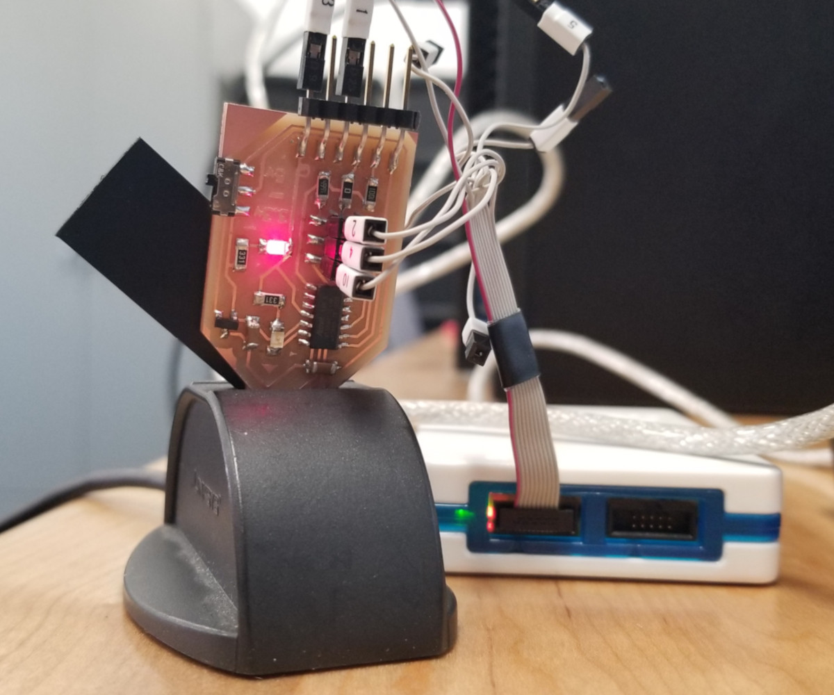
Looks like it’s been attacked by a flying spaghetti monster.
For Reference:
- Pin 1 = Target Voltage (Vcc)
- Pin 2 = SWDIO
- Pin 3 = Ground
- Pin 4 = SWDCLK
- Pin 10 = Reset
Then I downloaded a debugger tool called edgb, found here. I just used the most current version, which as of this writing is 32.
Then I downloaded the binary, or the SAMD11C Arduino bootloader core firmware. I’ll be honest, I don’t know exactly what this does, but it’s important.
Next step is to open the Windows command prompt and make sure you’re in the same directory as the files that were downloaded. This is IMPORTANT because this gave me trouble. This is the command Adam had on his site:
edbg-windows-r24.exe -bpv -e -t samd11 -f sam_ba_Generic_D11C14A_SAMD11C14A.bin
There’s nothing wrong with this command, except it doesn’t have the exact directory where I had the files saved, so it didn’t work initially. Garrett helped me do some troubleshooting and we figured out the problem. Another thing to note when doing this step is that the programmer needs to be plugged into the computer. Simple thing, seems obvious, but it’s only obvious if you already know what you’re doing.
Next is to install the software that the Arduino needs to program.
Open up Arduino, go to File => Preferences.

Click on the icon next to “Additional Boards” and paste:
https://www.mattairtech.com/software/arduino/package_MattairTech_index.json Then (there are so many steps to this, phew) I had to install the SAMD board.
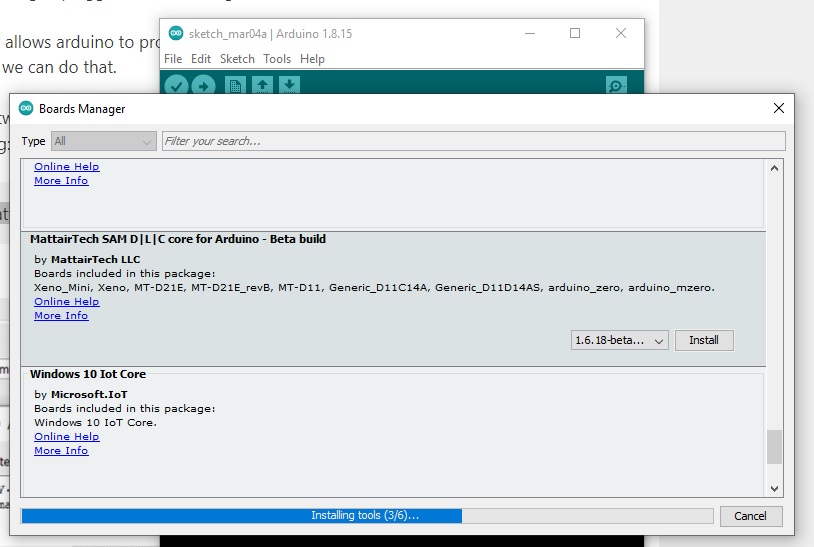
This is under Tools => Boards => Boards Manager. Search for SAMD to make it easier and install the MattairTech option.
Now we need to set up our options.
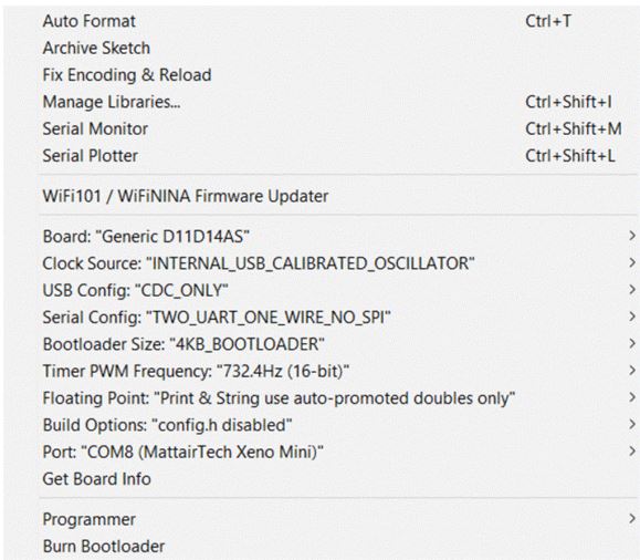
This is from Adam’s site. I forgot to snag a screenshot of this at the time.
Now we’re ready to test it!
Adam had a couple of programs ready to test our settings, so I used the LED program below:
int led = 2;

// the setup routine runs once when you press reset:
void setup() {
  // initialize the digital pin as an output.
  pinMode(led, OUTPUT);
}

void loop() {
  digitalWrite(led, HIGH);   // turn the LED on (HIGH is the voltage level)
  delay(1000);               // wait for a second
  digitalWrite(led, LOW);    // turn the LED off by making the voltage LOW
  delay(1000);               // wait for a second
}
AND IT WORKED!
And finally, I needed to make it into an actual programmer. I used the following code first:
void setup() {

   SerialUSB.begin(0);
   Serial1.begin(57600, SERIAL_8E2); //Adjust baud rate and use SERIAL_8N1 for regular serial port usage
}

void loop() {
   if (SerialUSB.available()) {
      Serial1.write((char) SerialUSB.read()); //Send stuff from Serial port to USB
   }
   if (Serial1.available()) {
      SerialUSB.write((char) Serial1.read()); //Send stuff from USB to serial port
   }
} //end loop
Then I could disconnect everything and add a jumper between two pins on the board.
Now I can use it to program other boards!
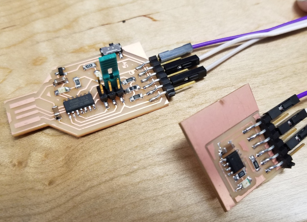
Using the Programmer
Garrett had a little blinky board to use to test my programmer. It’s not pretty (it shifted or pulled up at some point during the milling) but it still works. But once again, there are a few more steps we have to take before programming.
First, I had to install the board information on ATTiny chips, which is primarily what I’ll be using. The one in particular is an ATTiny412. I went back to Preferences and clicked on the icon for additional boards and put in the following:
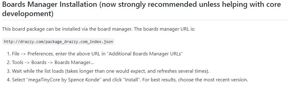
This gave me SUCH A HEADACHE! All the information about the library is found on Spence Konde’s GitHub, which is great, thank you so much, but the real question is where do I go from there? All the links I found always led to the main page, but nothing ever said what exactly I should look for. Some particular extension or file to download? Nothing.
So here it is! I found that information by going into the README.md on the front page, either scrolling down or clicking on the actual link, then in the first section, I clicked on “Installation”, and went down to “Boards Manager Installation”. Nothing to download, just copy and paste “http://drazzy.com/package_drazzy.com_index.json”.
My band director in high school had a favorite saying. She called it her 11th commandment:
Thou shall not assume.
And she was right. Do not assume the person reading the instructions knows what to look for. I certainly didn’t. Moving on.
It works!!! Blinky board blinks!
Group Project
The next group project information can be found here.
Files
Resources
-
Adam’s Website: Multi Use Board
-
Adam’s Site: How to Export to a CNC from KiCAD
-
Roland SRM-20 User Manual