9. Molding and Casting
Once again going with the tried and true Fusion, but this time it’s also because I use the CAM side of it at work all the time.
Using Canvas
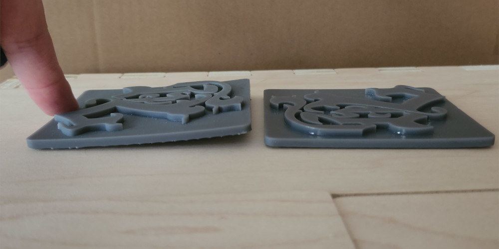
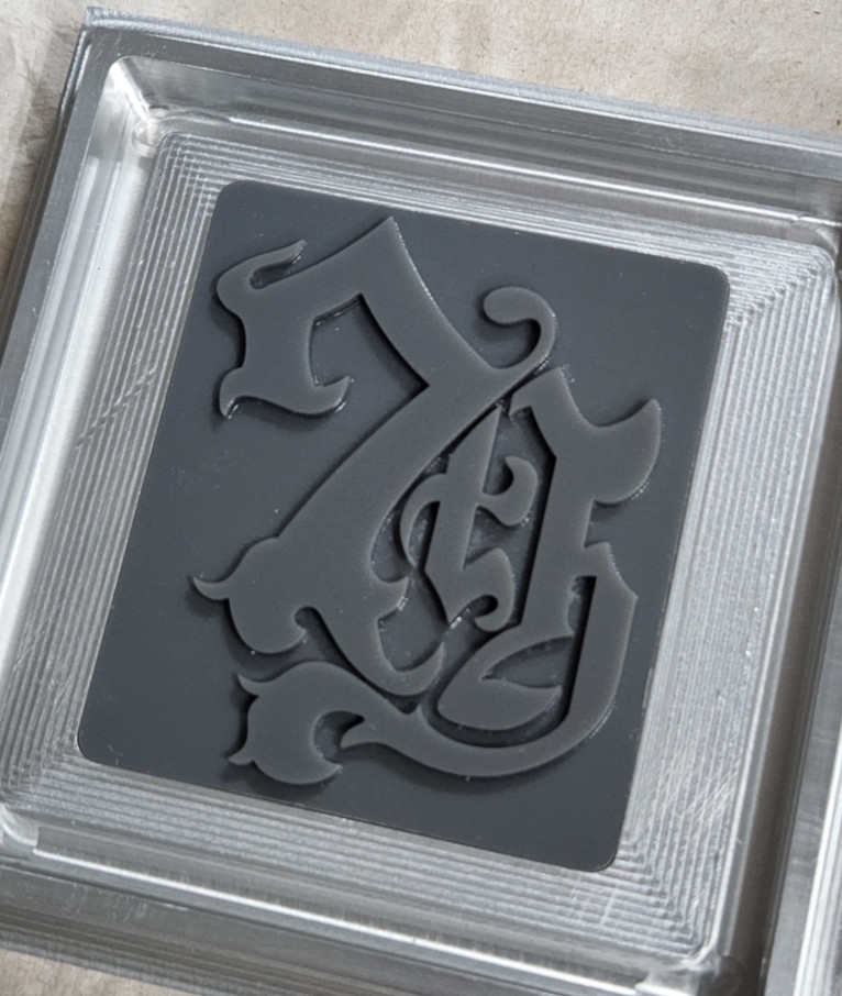
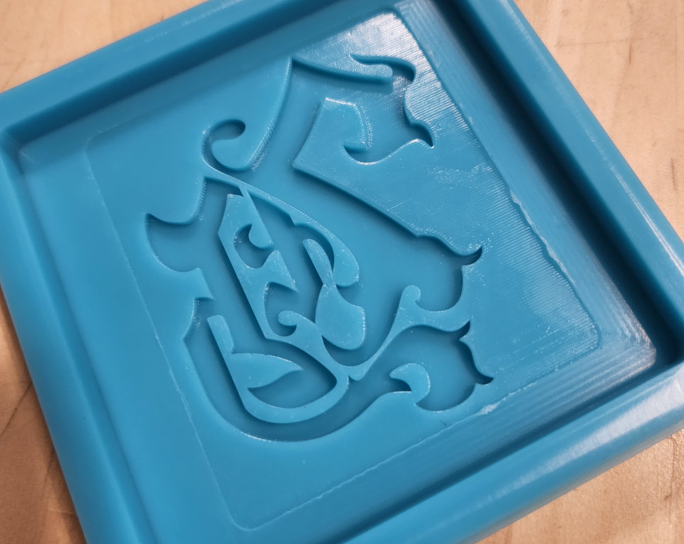
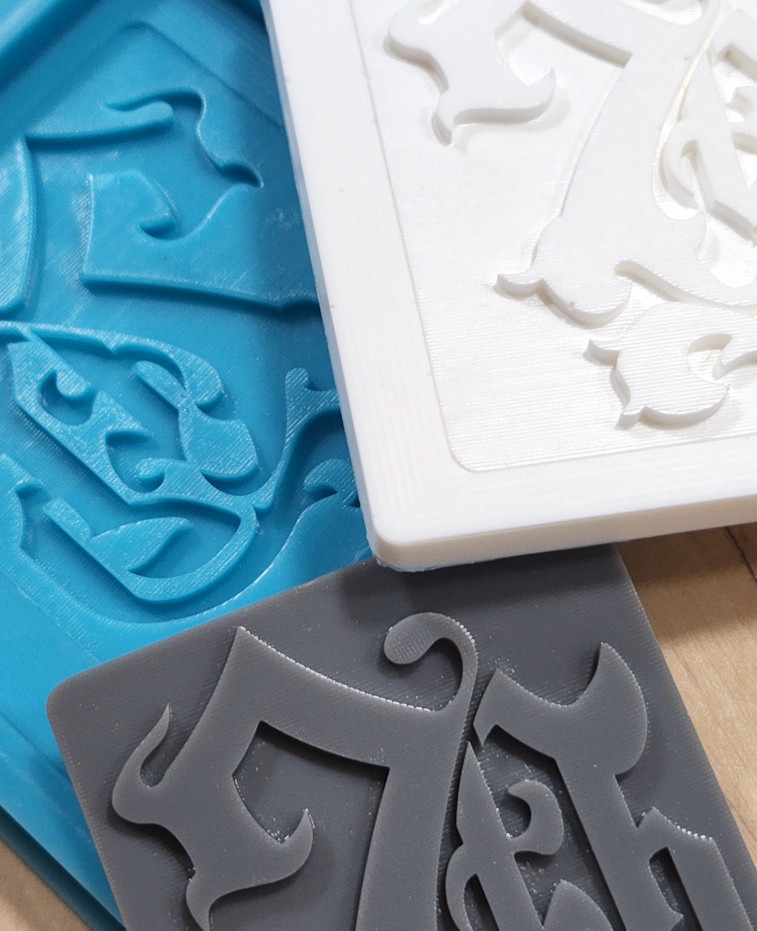
I had a hard time coming up with a design, so after some brainstorming and asking for suggestions, I came up with a simple coaster, but wanted to make it more interesting, so I added a design based on one of my favorite games. Unfortunately, the details are too small for the Haas, so I’m going to print an insert on the resin printer.
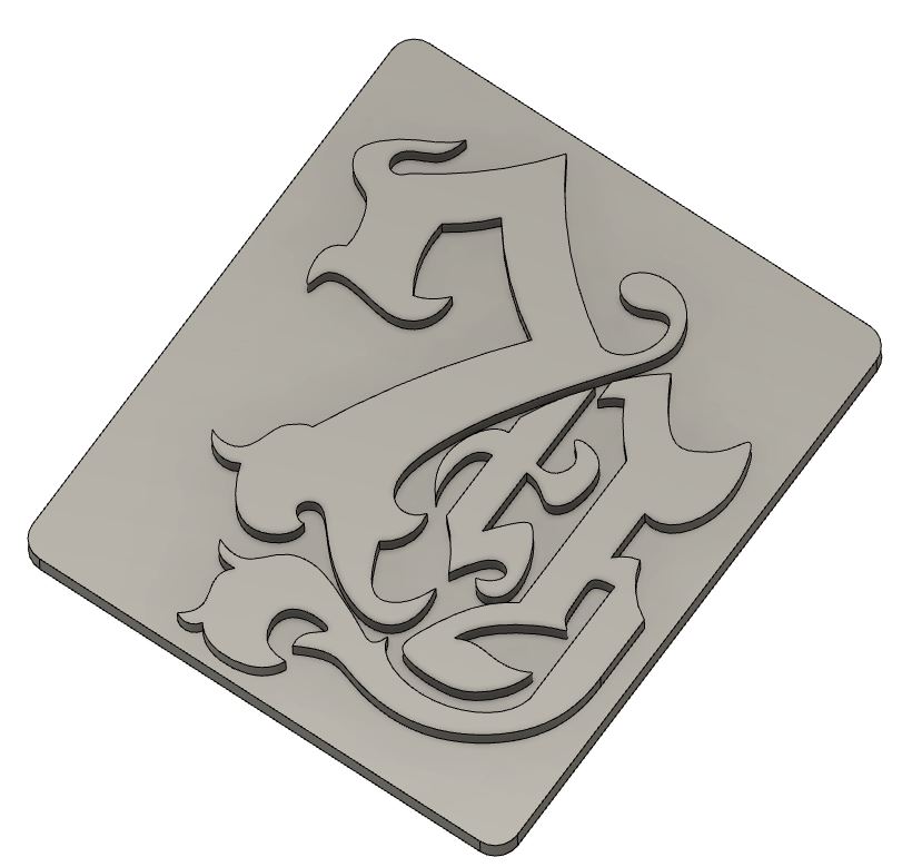
The design I wanted is rather elaborate, so to get an accurate version, I found a picture of the logo online and imported it into Fusion as a canvas. I made sure to import it into the bottom of the pocket where the insert would be, and it luckily came in the correct size. I was worried I would have to scale it to make it the right size.
Then came the tedious part. I decided to do each letter and number in its own sketch, so I started with the “7”. I made good use of the “Spline” option as it allowed me to adjust each curve and point until I was satisfied. I also used the “Arc” and “Line” options on the shorter or simple sections, but I used them sparingly. I would run into problems if I adjusted the end point of a spline that coincided with an arc endpoint. If I moved the point to adjust the spline, the arc would move as one solid piece, which changed and sometimes ruined the shape, and I’d have to redo it.
However, for as time consuming as the process was, the end result came out amazing and I couldn’t be more happy with it.
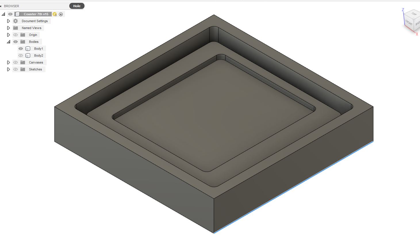
Last, I needed to create the shape of the coaster itself. This part gave me some issues; I just couldn’t wrap my head around it.
I had decided on doing a two step mold. Because this is being machined from aluminum, chances are resin wouldn’t release very well, if at all, from the block. To eliminate this, I decided to do a silicone mold first, then use that to cast the final resin part. Theoretically, all I had to do was create the coaster and then build around it, but switching between the positive and negative forms in my head confused me. In the end, writing and drawing it out was the best way to keep everything straight, and I finished up the main mold.
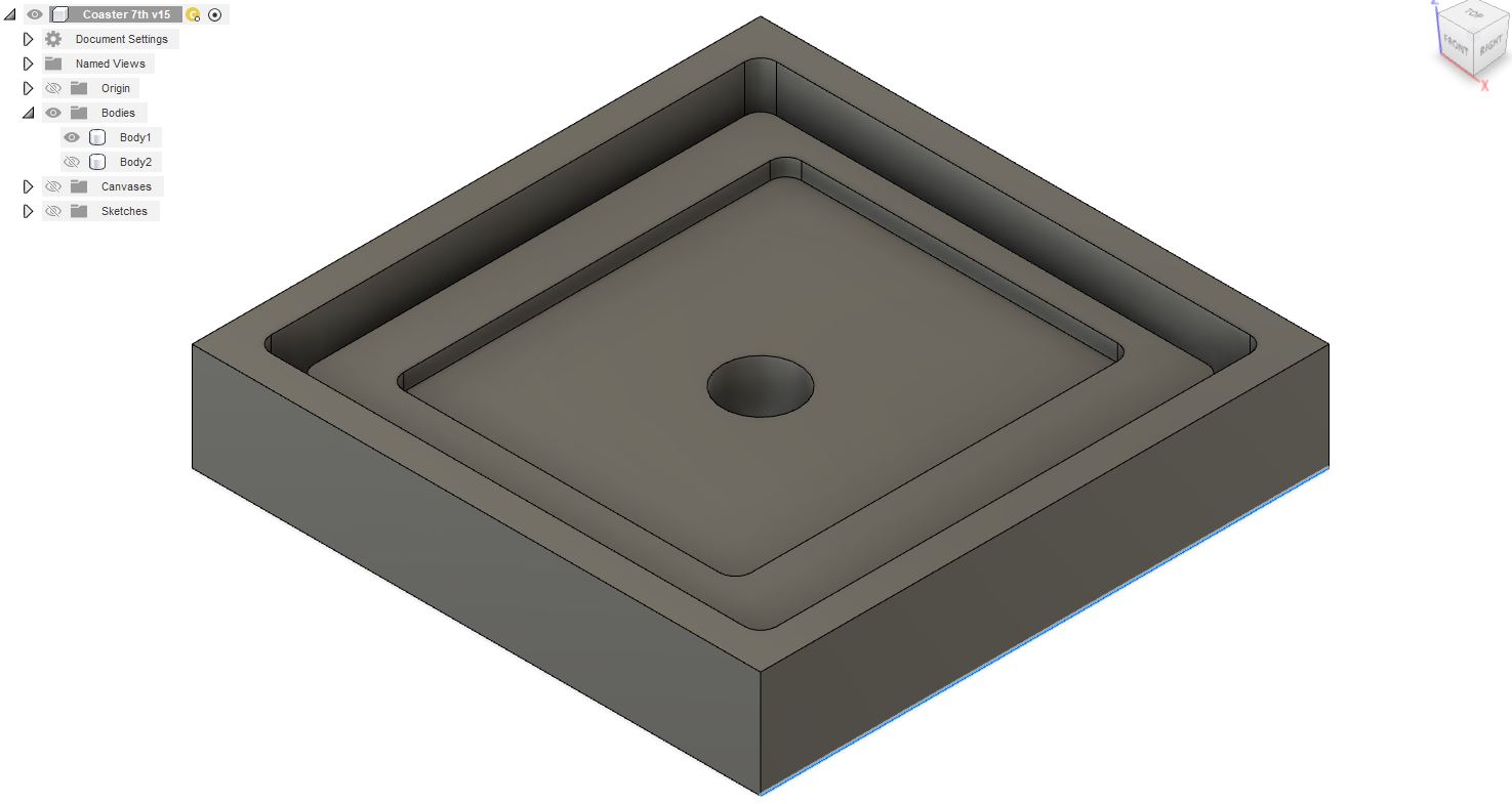
After meeting up with Garrett at the lab and showing him my part, he had the suggestion to make the insert removable so I could make different versions. After all, why not have a whole set of coasters? Who needs just one?
I hadn’t thought of that originally, but it was an easy thing to modify. All I had to do was add a hole in the center under the insert so I could remove it easily and change it out.
Printing
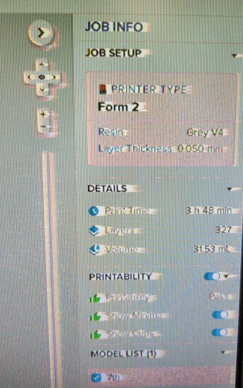
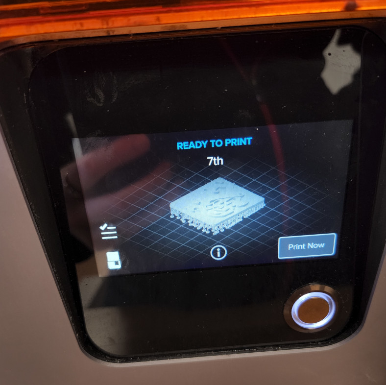
Next, I took the insert piece, saved it as a STL, and set it up on the Form 2. I immediately ran into another couple of issues.
First, the computer screen decided to shift? I’m not sure how to describe it. Not only that, everything seemed to slow down; programs didn’t open very quickly, they were slow to respond to mouse clicks, there was lag while typing, so on and so forth.
Restarting the computer didn’t fix it, so it was a problem with the monitor, at least from the graphics side. I wasn’t sure how to fix the slow processing, so I worked through it, though it made the process a bit more difficult than I liked.
One of the things that was most difficult was setting up the print. I knew that due to the wide flat bottom, it was best to angle the part slightly and add supports so it wouldn’t adhere directly to the bed. This would have made it extremely difficult to remove. But because the computer was lagging so badly, I couldn’t make any fine adjustments to the position of the part. I could either have it angled more than I liked, but still acceptable, or it would spin and rotate way more than I wanted. In the end, I just settled for the closest I could get.
I then adjusted the supports from 100 percent coverage to 50 percent, and changed the raft from a full size to multiple smaller pads. This helped bring down the print time a bit, and that level of support just wasn’t necessary. The original print time was just around an hour, but I increased the resolution to 0.05mm, one step below the finest resolution. This brought the time to just over 4 hours, but with my support adjustments, the final time was 3 hours and 45 minutes, give or take. I sent the job to the printer and encountered my second issue.
The Form 2 did not recognize that it had a resin tray installed. It said it was missing, even though it was there and, as far as I’m aware, was never moved. I removed it and put it back a few times, but it still couldn’t find it. I then took it out entirely and cleaned the contacts with alcohol, both on the printer and the underside of the tray. There was a bit of resin that look like it had oozed around the contacts. Most likely this is some that I was unable to get to and clean out during my TLC and cleanup. After wiping it off, I installed the tray and it recognized it just fine.
A quick Google search found that this is a known issue with the Form 2, that there are times it will fail to recognize a tray that’s been there for previous prints. I’m sure the excess resin didn’t help either.
Shopping!
By this point, it was time for Garrett and I to meet up with Adam to get our mold and casting materials. We went to Reynolds Advanced Materials, and it was AMAZING!
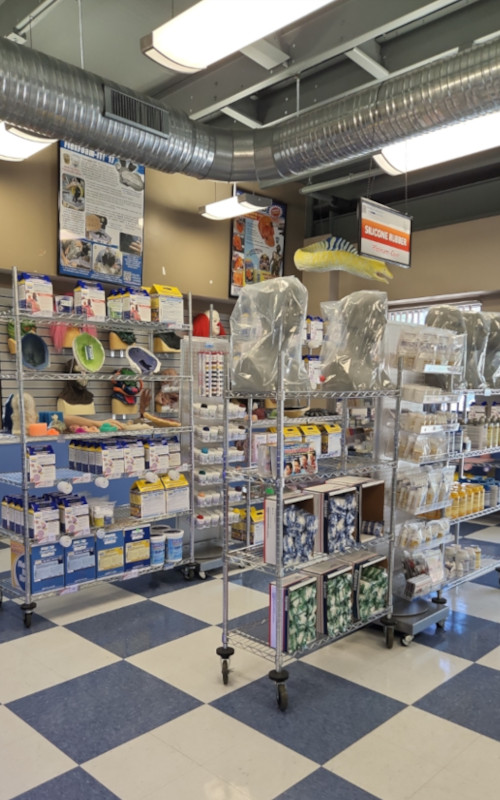
They had examples for every type of silicone, urethane resin, and standard resin, from face masks, props, models, molding examples, almost anything you could think of. It was a touch overwhelming at first since I didn’t know where exactly to start, but I knew I needed silicone, so we started in that section.
The associate working there was incredibly knowledgeable and answered all our questions and had tons of tips to get the highest chance of success. I wish I had recorded him, but here are a few things I remember:
-
Silicone shouldn’t have a problem releasing from aluminum. However, to be on the safe side, it’s best to use a mold release and to make sure that the surface of the mold is completely clean. No oil, chips, dirt, grime, as clean as possible, then apply the mold release.
-
If you plan on using a 3d print as the mold, it needs to be sealed with an acrylic sealer or the resin/silicone will not set. Apply a few thin layers of the acrylic sealer and make sure to cover absolutely everything that will touch the mix. Once completely dry, apply a layer of mold release.
-
Certain silicone mixes don’t require degassing, or the removal of gas/air bubbles in the mix. This is mainly because they have a thinner consistency, allowing the bubbles to more easily rise to the surface. The thicker mixes should be degassed with the use of a vacuum chamber, but only if the working time, or pot life, allows it.
Terminology
Just a few terms to note during this process.
-
Degas - This is basically when bubbles and air pockets are removed from the mixture, almost completely eliminating the chance of bubbles forming on the mold surface. The most common method is by using a vacuum chamber of some kind. The mix is placed inside the chamber and a vacuum is pulled, which forces the air pockets and bubbles to rise through the mix to the top. This process is only done if the pot life, or working time, of the mix is long enough to allow time for a vacuum to be pulled, as it can take anywhere from 10-15 minutes to achieve the desired amount of bubble removal.
-
Pot life - How long you have to work with a mixture once both parts have been combined before it starts to set up and/or harden. This can range from a few minutes to almost an hour. Due to their viscosity, silicone mixes tend to have longer working times while resins, with their more runny, almost water-like viscosity, can have much shorter mixing times.
The Materials
Since I decided to do a two step mold, I have two different materials to work with. I highly recommend reading through the pages related to the specific materials, and just looking through their site in general. There is a ton of useful information, instructional videos, and fun projects on every page. It’s no wonder so many people get into molding and casting. I’d love to dig deeper into this stuff.
Silicone
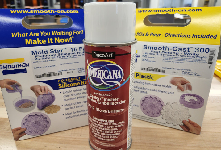
The silicone is on the left. This mixes into a really pretty teal color, very satisfying.
Name: Mold Star 16 FAST
- MSDS
- Mix Ratio: 1:1
- Pot Life: 6 minutes
- Cure Time: 30 minutes
Notes and Observations (taken during the use of the silicone)
- Is thicker than the silicone mix I use at work, almost a syrup-like viscosity
- Does not require degassing or use of a pressure pot to remove air bubbles
- The material is viscous enough that air bubbles don’t have a problem rising through the mix to the surface
- Am able to quickly mix and add more to the mold if done within a few minutes of the first batch. Initially found I made too little and had to mix up a second batch to fill the mold completely. Did not have problems with two batches separating or not mixing together
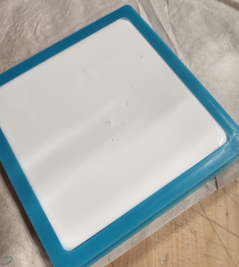
Resin - Urethane Plastic
The resin is on the right. The mixture starts out clear, then quickly transitions to solid white.
Name: Smooth-Cast 300
- MSDS
- Mix Ration: 1:1
- Pot Life: 3 minutes
- Set Time: 10 minutes
Notes and Observations
- This mix transitions very quickly, and will begin curing if a catalyst is introduced. For example, if agitated by tapping on the mold, or by moving a scribe through the mix
- Seems to pull away from corners of mold though. Curing looks like it happens from the middle or center of the mix out to the edges, then it slows way down
- The surface is extremely smooth with very few air bubbles Is difficult to remove air pockets that are trapped in tight corners and small spaces simply because the resin seems to react to any agitation, so it will begin to set as you’re trying to pop the bubbles
- It takes much longer for the resin to set if in a fully enclosed mold as opposed to one with an open top It takes longer still for it to set if pigment is added to the mix, and if not mixed well, will not fully set, resulting in gummy or sticky sections
Acrylic Sealer
This is the spray can in the middle of the previous pictures.
Americana Acrylic Spray Sealer
When talking with the associate at the store, he recommended using an acrylic sealer on the resin prints to prevent the silicone from reacting poorly to the surface when it was poured. This is what we found at Michaels, a craft store, but there are plenty of other options out there.
We bought the cheapest one we could find, that way if it didn’t work, or we bought the wrong thing, we weren’t out much money. As it turns out, this stuff worked just fine, and I had no issues with the silicone reacting to my resin print.
The Insert
Once we got back from shopping, I checked on my insert, which was now finished. I decided to try the alcohol wash station with the print still on the bed, so I loaded it in and set the timer to clean for five minutes.
After it finished, we pulled it out and noticed that there was still a lot of resin on the part. We put it in again and lowered it into the chamber when we noticed that the alcohol didn’t reach the lowest point on the print. At first we thought this was a design flaw, but then we realized that the alcohol was well below the fill line range. The line was a bit hard to see as it’s a black line against a dark grey container.
(Pictures of the resin wash and curing stations can be found in Week 4, 3D Printing)
After letting it wash, I removed the supports, which were very easy to take off. Since the text is very close together in places, there was still some resin in the channels. I put it back in the basket one last time and did another quick rinse. Once finished, I dried it off and put it in the curing station for 20 minutes.
This is where I made a mistake. Since the insert is wide and flat, it’s easy for it to warp. I didn’t realize this at the time, and when I took it out of the curing station, it was warped on all sides.
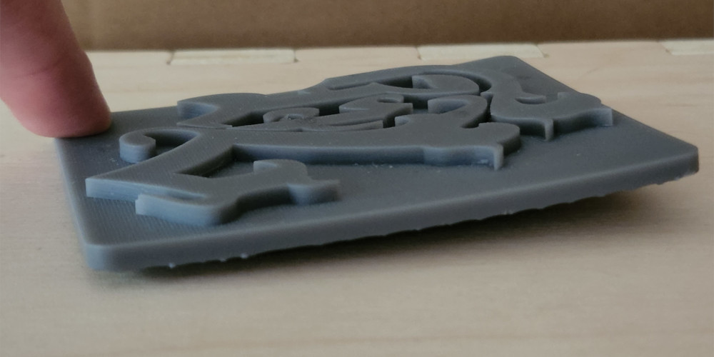
Unfortunately thus made the part unusable. It has to sit flush in the pocket. I had never experienced this before, so once again, a quick Google search was needed. I found a couple posts on FormLabs forums about the issue. When prints are washed in the alcohol, they tend to swell slightly. This usually isn’t a problem for bigger prints, but the swelling can cause problems in thin sections or flat prints. When a print is put in the curing station, that alcohol evaporates very quickly, because the station is also heated. That rapid removal of moisture causes the print to contract, which causes it to warp, which is then set permanently when it cures.
Some people suggested heating the print in an oven to soften it enough that it will flatten out, but I don’t have access to one or time to try it. This time, I’ll just have to reprint the insert.
However, once it’s finished, I’ll make sure to let the print dry entirely before moving on to final curing. Hopefully that, at the very least, mitigates the problem. The other thing that may have caused a problem was how I removed the supports. The print was soft, so I may have bent it inadvertently while removing the supports and cleaning it up. I’ll make sure to handle it with more care next time.
Update on Resin Print
Garrett was kind enough to clean and finish another two prints for me this week. The first one that I had started printing before leaving for the night, also ended up bowing once cured. Garrett had cleaned and left it to dry, but it must not have been fully dry, so it started to bow again.
After a few quick Google searches, we found a couple methods to try to prevent the warping. First, like I mentioned before, the part needs to be COMPLETELY dry before being cured. This means leaving it out for much longer before putting it in the curing station, even if the part looks dry on the surface. The other part was how quickly the part cured.
The curing station has an option to heat up as well as use the light. It may be that the heat was causing the part to warp also, again due to the alcohol evaporating more quickly on the side with the heat versus the light on its own. In the end, Garrett cured it the old fashioned way, by leaving it out in the sunlight to cure slowly.
The third piece did warp slightly in the corner, but the overall results are WAY better than the first attempt. I’ll call that a win, and something to experiment with down the line.
Back for More: Machining
This is the part I love, actually machining what I designed. Plus, doing it on a Friday means I had the whole shop to myself (at least until Garrett showed up).
I had to make some tweaks to my program before running anything though. The raw stock we have that’s closest to my part is 5”x5”. My part is 4.5” square. Not a problem, I just had to adjust my stock size to make it bigger in Fusion.
I took that time to also double check my toolpaths after they updated. Everything still looked okay, so I reposted my program and went downstairs to the shop.
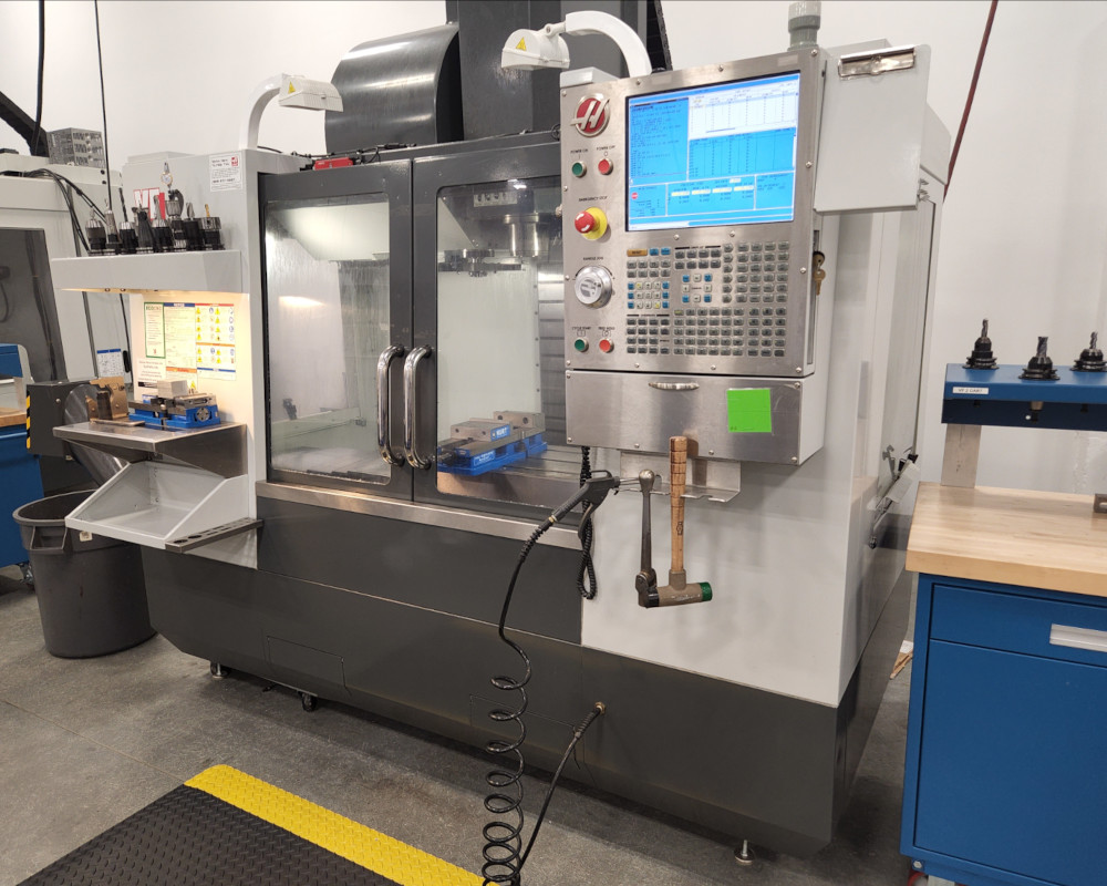
We have multiple Haas machines, but due to wear and tear from students and age, sometimes you have to find the one with the least amount of problems.
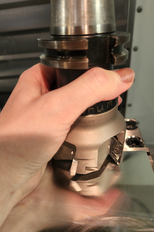
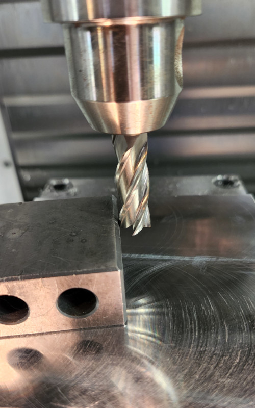
The first step in making a part, once the part is located in the machine, is to face the stock, which means taking a large end mill or shell mill, also called a face mill, and removing a small amount of material from the top. This is done just to clean up the top surface before moving on to machining the surface. Usually this is added into the program as the first toolpath, but since I could, I simply went across the surface with the hand jog and a simple program to turn on the face mill and cleaned up the surface by hand.
I wrote the program for this at the controller. I used the MDI (manual data input) screen, which allows you to execute short commands instead of creating an entire program.
- T1 M3 S1500
- Called Tool 1, turned spindle on clockwise at a speed of 1500 RPM
Once that was done, I used an edge finder to locate the center of the part.
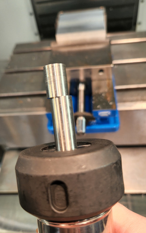
The end is held on with a spring that allows it to wobble off-center from the rest of the tool. When it touches the side of the part, it forces the wobbling portion to begin to align with the tool. You continue to feed the tool into the part until the end is perfectly aligned, then slightly past, causing the end to kick out again. That’s how you know where the edge of the part is, plus the radius of the tool.
This is another tool that is used in MDI, this time by simply changing the speed. Because the end isn’t held on by much, it can’t be used with high speeds (the end will just get flung off if it spins too fast). We usually run them at 750 RPM. At work we use 500 RPM. Both speeds work just fine, but anything higher than 1000 RPM increases the chances of ruining the tool.
First, I located the edge in X, then I zeroed my location. I moved to the other end of the part in X and touched off the edge. I then divided the distance traveled in half and moved my tool to that location. Once there, I pressed “Part Zero” on the controller, and updated the information in the Offsets screen. I did the same in Y, and then I had the very center of the part.
I find it’s easier to program from the center. This allows for some variance in the stock sizes without having to readjust each time. As long as the stock is not too small, or wildly larger than necessary, the part will always clean up. This is also how I program parts at work, though in that case, I use a touch probe, which is much faster and more precise than an edge finder. It can also be automated and/or integrated into the program.
The last thing I did was touch off the length of the tool I was using. I did this by using a 123 Block, or a 1” x 2” x 3” block of steel.
These blocks are ground to be exact, so when I brought the tool down and just barely touched the surface, I knew I was “exactly” one inch above my part (“exactly” because this was done by hand, which is good enough for this particular job). I used “Tool Offset Measure” and made sure it updated the correct tool number to correspond with the tool in the offsets page. Then I dropped the measurement down another inch to account for the block, and I was ready to go.
Because I’m paranoid, I double checked my program, then went for it. I put a stop in the program after the first tool because I needed to find a ⅛” tool. I wanted to make some progress while I searched. I had found one that was too long and another that was a ball nose end mill, but neither of them were good enough for what I needed. Luckily Garrett found a good end mill. When it was time to use that tool, after putting it together, I touched it off and continued running the program.
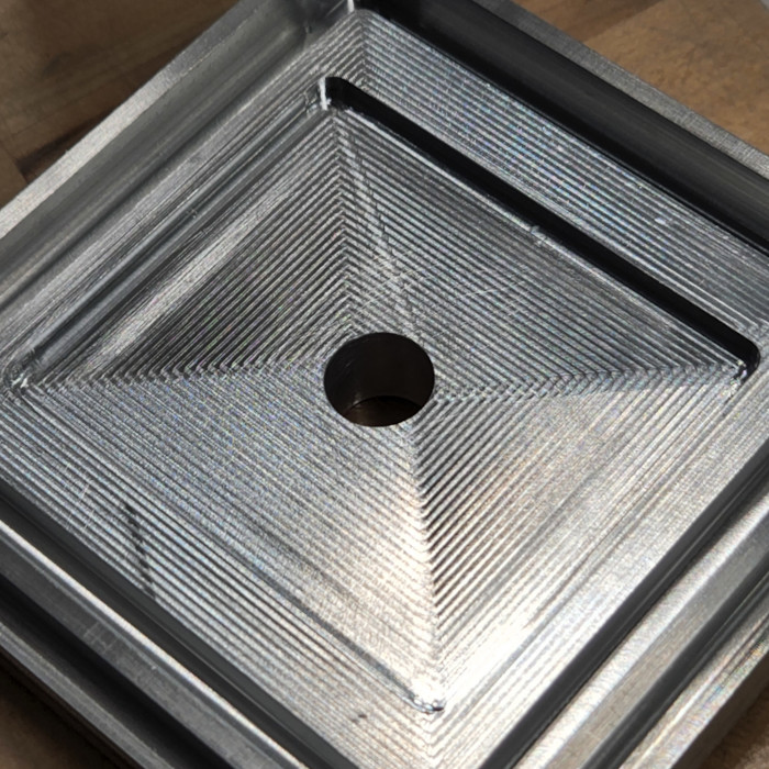
Not too shabby!
The first run went well, but the insert didn’t fit. I measured the insert and realized it was 10 thou (0.01”) oversized in both directions. After bringing this up with Garrett, we figured this was attributed to the alcohol bath, which probably caused the part to swell. The interesting thing was that it was an equal amount in both directions. I don’t believe it was a measuring issue either as the part was modeled directly from the base machined model, and the diameter of the tool wasn’t off by that much.
After trying to sand the edges of the insert to fit (which was a pleasant surprise to find that resin sands as well as it does), we decided just to try again. Since it was the second time running the program and it had been “proven out”, I let it run and worked on other projects I needed to finish.
When I came back when it finished, I found that the ⅛” end mill had snapped off at some point, so the channel was unfinished. We found another tool, though this time it was a ball nose, and ran just that toolpath again. I watched it run so I could locate the problem, and saw it had a really hard time cutting the channel. The tool walked all over and chattered like crazy before it finally snapped off.
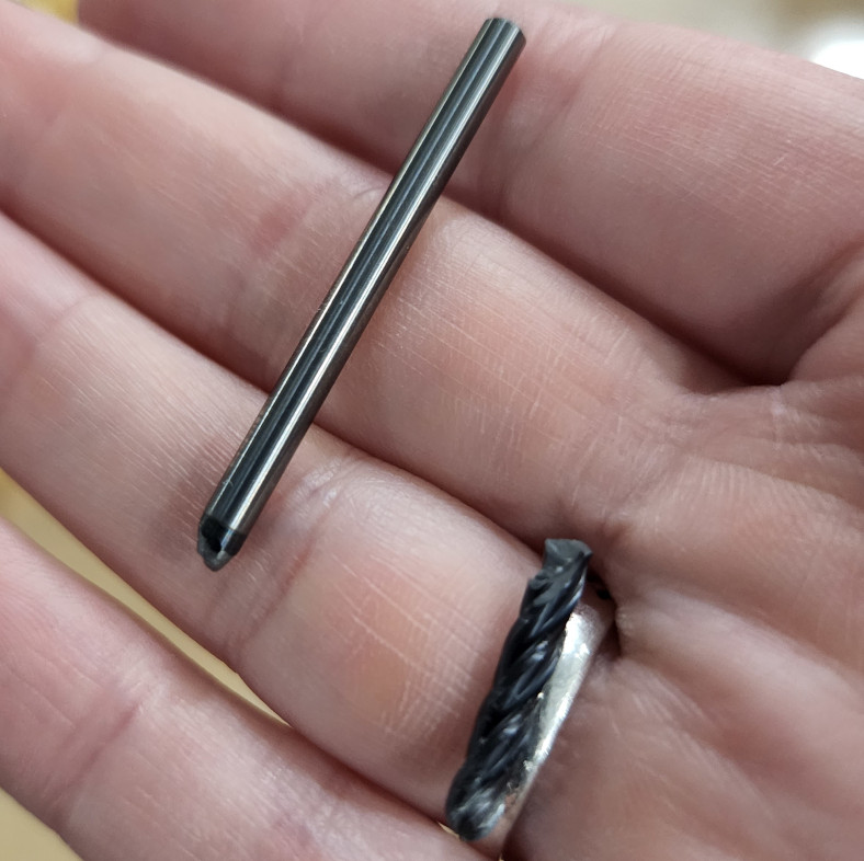
The interesting part was that it managed to cut the first part just fine. I’m not sure how it was able to handle that load without issue round one, but I guess it only had one round left to give.
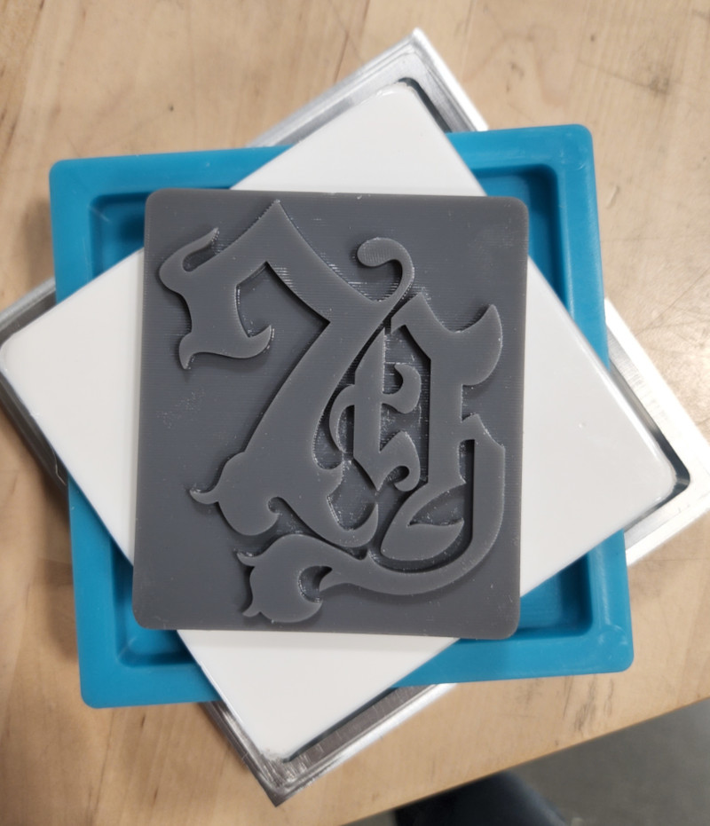
After those failures, I decided to widen the channel to ¼”. This meant I had to redesign the part. It wasn’t too difficult, then I fixed the toolpath, grabbed a new tool, touched it off like before, then ran the last toolpath. This time, it worked out great, and the channel looked way better.
Once finished up, I cleaned out any coolant and chips using alcohol, which is really effective at getting any residue off the part. Then it was time to test fit the resin insert, and luckily, it fit much better! Better being closer. It still needed some adjustments, specifically that the radii on the insert matched the pocket, so they interfered when I tried to press fit them together. Let this be my note that I need to change the radius of the corners on the resin part, make them slightly smaller so it doesn’t interfere with the corners of the aluminum.
Once satisfied with the fit, I had to prep the parts.
Casting Fun Times
First I covered the resin printer with the acrylic sealer. I used multiple light coats, letting them dry in between. My main concern was how close the space between the lettering was, and if I would be able to get enough mold release between them. If not, then the silicone might stick and potentially tear when I try to remove the mold, but the only way to find out was to try. Once it dried, I pushed the insert into the aluminum and applied a layer of mold release to the entire mold and let that dry. The corner where it warped protruded slightly above the floor of the pocket, but it wasn’t too bad overall.
I laid out everything I would need, gloves, paper towels, cups, the mold, and any extra molds. Since we had done the group project earlier, I had a better idea of what to expect and the kind of workflow I would use. I estimated how much of the mix I would need, but having too much is better than too little. Garrett also prepped his mold so I could pour the excess in there. We also had a part that had been floating around the shop for a while with some rather impressive chatter marks. We decided if we had enough we would also cast that.
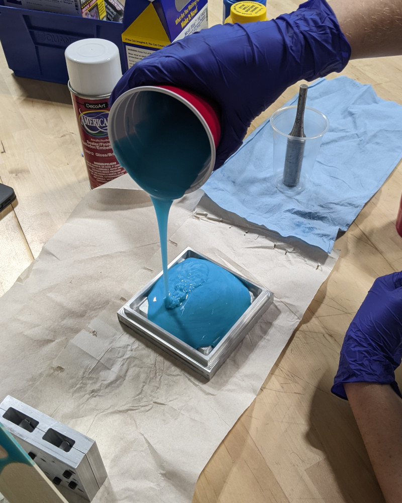
I can’t believe I got it that perfect. Not a single spill.
I ended up with a good bit extra, so I poured into Garrett’s mold and the rest we poured into a cup that held the metal part. There wasn’t enough to coat it, but it may have worked better if we had a more narrow cup. So instead, we covered the part and kept rotating it until the silicone started to set.
Came out looking like a corn dog.
While I waited, I cleaned up the machine and put away the tools I used. The set time on my particular silicone mix is 30 minutes, so once I was finished with the machine, it was just about time to check the results.
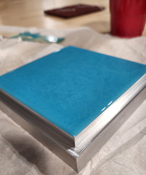
It looks amazing!
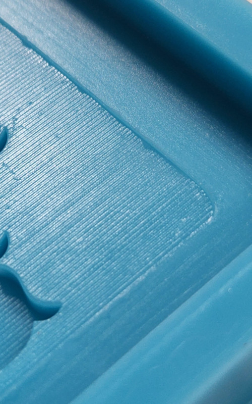
I’ll admit, I was a bit nervous with how the mold was designed, but it turned out to be a great happy accident, especially given how the silicone flowed across the edges. The excess gave me something to grab as I pulled the silicone out of the mold. It came out easily and I was extremely happy with the results. The level of detail was amazing. I expected to see the layer lines on the resin print, but I was not expecting to see the toolpath marks as well.
No matter how many times I use silicone, it never ceases to amaze me. The detail is insane.
Then it was on to the resin itself. I used the same process as before, and used two cups to measure out the two parts, then poured it all into one cup to mix. After thoroughly stirring, I poured the resin into the silicone mold. I had a bit left over, so I poured that into the extra mold we made as well.
After pouring, there were a few bubbles I could see trapped in the sharp corners of the print, but when I tried to use a scribe to dislodge them, it set off the curing process of the resin. It was awesome watching it change from clear to white so quickly, even though that meant I had to live with the bubbles.
As it cured, I noticed that the corners of the resin seemed to pull away from the mold. The rest of the mold remained flush against the walls. After thinking about it afterwards, this may be due to shrinkage, but I’m not entirely sure. However, this didn’t affect the quality of the resin overall.
I’m so stinkin excited about how good this looks!!
I was amazed at the quality of the coaster. Honestly, this will never get old. I have lots of plans for this in the future.
Group Project: Making Anything Work
The group project can be found here.
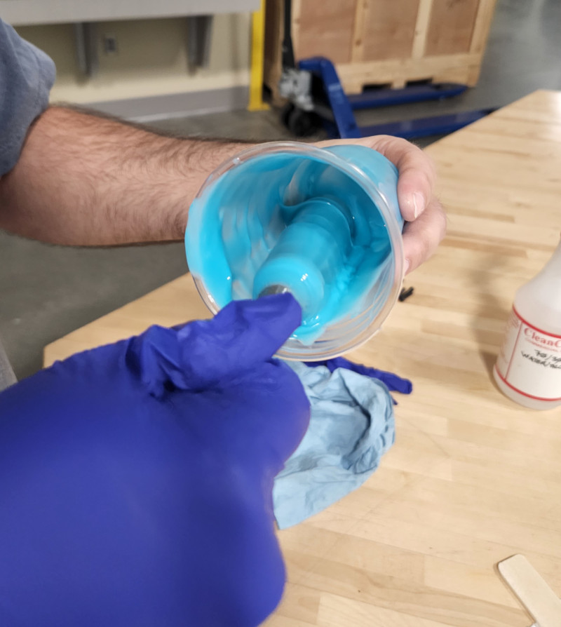
This week, Garrett and I worked together to test the few silicone and resin mixes we’ll be using for our final parts. We don’t have a dedicated area for molding and casting, so most, if not all, of our setup consisted of items found around the lab. We also didn’t have much to cast, which is why we used the lid off my takeout cup. I did most of the mixing and pouring since I had a bit more experience working with silicone at work, and we both worked on mixing the colors. Overall, we both had a lot of fun with this project and learned a good bit just from playing around.
Files
Below are the files for the mold and insert:
Below are the programs and setup sheets for machining the mold: