2. Computer Aided Design
This week was all about 2D and 3D design. Our assignment is to create our final project using multiple programs.
Fusion 360
Since I use Fusion 360 on a daily basis for work, I decided to start there as an easy way to get the baseline for my project. That way I have something modeled quickly, and can spend the rest of the time on programs I’m not familiar with.
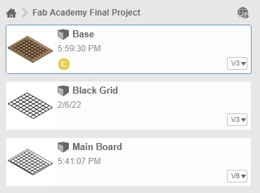
I started by creating a new folder in Fusion 360 for my files so I could have them all in one place. My goal is to create the different layers I’ll need to complete the project, such as the top layer for writing, the black lines, possibly embedded, and then the base or backing where the electrical components will reside.
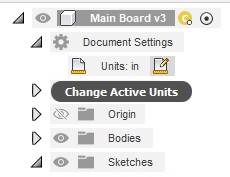
Fusion always starts with an untitled file, and defaults on the design space. I first changed the units from millimeters to inches. I use millimeters at work almost exclusively, so I’ll have to keep this change in mind as I work. This is found under “Document Settings” on the left side of the screen, in the drop down menu.
First thing to do is create a sketch. Across the top in the ribbon menu are all the options available under the design view. From the left, the first menu option is sketch. Once selected, it will ask which view you want to use. I’m going to model from the top view, as though I have the board on the floor and am looking at it from above. From there, I modeled the basic shape for my calendar. Since it’s a simple rectangle, I used the “rectangle” tool from the options along the top. Notice that the menu changed when we’re in sketch mode. For now, I’m not concerned with the size, I can change those parameters later. First I wanted to get a rough shape. Once set, I can add dimensions.
In the menu across the top, in the first section called “Create”, the last icon is two lines with an arrow pointing to each side. This is the dimension tool, which allows you to set how big your sketch is. If you need to change dimension sizes later, you can always double click on the number you need to change, and update it. I’m going to base the size on a sheet of posterboard I happened to have, which is 28” x 22”. To dimension, click on the line or feature, and a box will open, allowing you to enter in the size. Once dimensioned, the line will turn from blue to black, meaning it has been fully defined. You can also use the keyboard shortcut “D” to quickly bring up the dimension option.
Once finished with the sketch, you can select “Finish Sketch” from the top menu, or from the popup menu.
Then I needed to make my sketch a 3 dimensional part, so I selected Extrude and made it .5” thick.
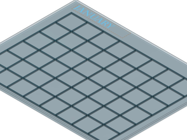
The next thing I needed to do was create the grid for the calendar itself. I selected “Sketch” again, but this time, I selected the face of the extruded part. Again, I used the rectangle tool to create a square, but this time I based the dimensions off a post-it note I had laying around, so 3” x 3”. Creating each individual square would be tedious and a hassle to keep aligned, so I used the “Rectangular Pattern” option from the menu.
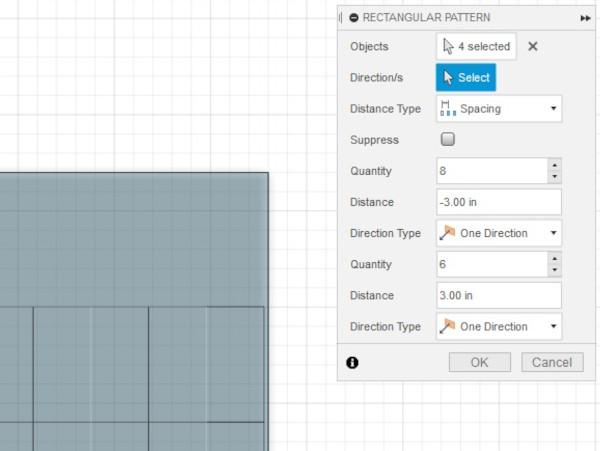
This let me choose how many squares I needed in both the right and down directions, quickly creating a grid. Once set, I also set the dimensions for how far I wanted the grid to sit on the board so that it is centered from left to right, but also slightly offset from the top to allow for the month. Then I finished the sketch.
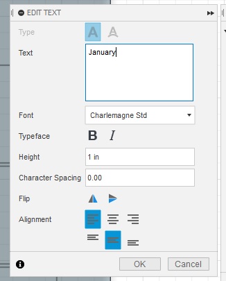
I wanted to see where the month could be placed on the board, so I created another sketch, and again selected the face of the board. This time, I used the “Text” option. This is in the dropdown menu of “Create”. I created the text box, then entered in the information I wanted, including the font, the height of the text, and other features. Once satisfied, I hit okay and finished the sketch.
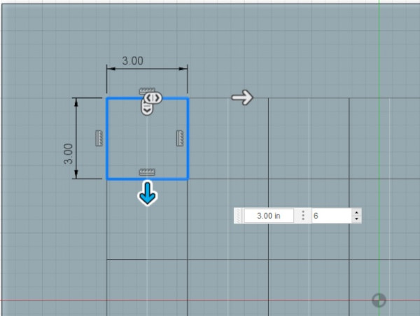
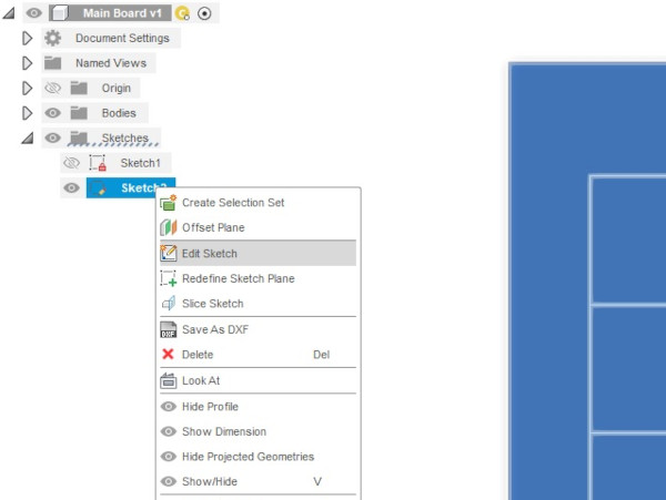
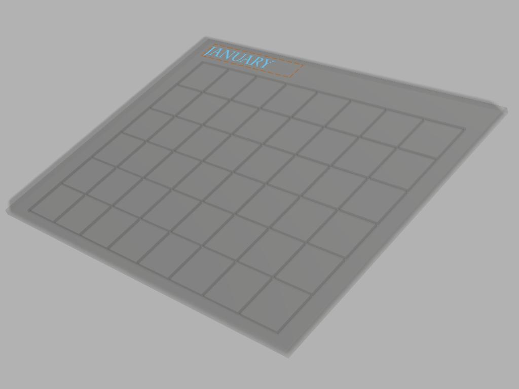
The last thing I noticed was that my grid was too close together. I needed to have space between each box for the black lines that separate them, so I had to adjust the spacing. I went back to “Sketch2” on my side menu, right clicked, and selected “Edit Sketch”
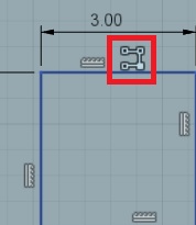
Then I selected the pattern icon on just above the first box I based the grid off of. From here, I made the adjustments I needed, including recentering the grid with the new dimensions, and finished the sketch.
Last, I needed to create the grooves that would house the material for the grid to separate the squares. I did this by creating another sketch, and selected the bottom of the part instead of the front, since this is going to be the back of the finished part. I recreated the grid with the new dimensions that accounted for the width of the lines, then finished the sketch.
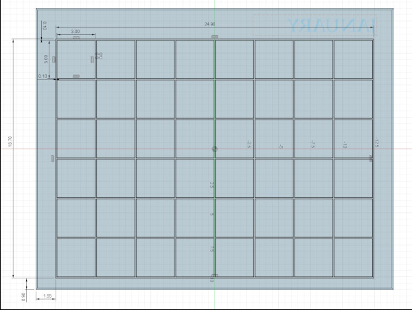
Note that January is backwards in the sketch.
You’ve probably noticed that I use multiple sketches when creating features. This is kind of like using multiple layers when creating digital art. It’s much easier to correct or adjust a feature if it has its own dedicated sketch, than to try to sift through one large sketch to fix one problem. It’s also good practice to name the sketches according to what they’re for, for reference and again, to make it easy to find the correct sketch to adjust.
I decided to add a fillet around the top edge of the part, mostly for looks, but also as something that may be necessary for assembly in the future. I’m not sure how this will be assembled yet, but there’s a chance that this top part will be completely exposed, so having a rounded edge is both a more finished look as well as safer for handling. This option does not require a sketch. Across the top in the “Modify” section, select the “Fillet” tool.
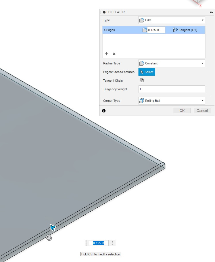
I played around with the size of it, but ⅛” seems like a good starting point.
Finally, I used the Extrude function to create the grooves in the part. I had to zoom in a bit to select the thin features, but once selected, instead of extruding up, I extruded down into the part, and made a cut into the solid part, creating the channels I’ll need later.
Remember to save often!!! Fusion lets you put in a note when you save for your reference, but it’s not required. In addition, each time the file is saved, it creates a new version, which allows you to go back to older versions if you need to start from scratch or to see exactly what changes were made from version to version.
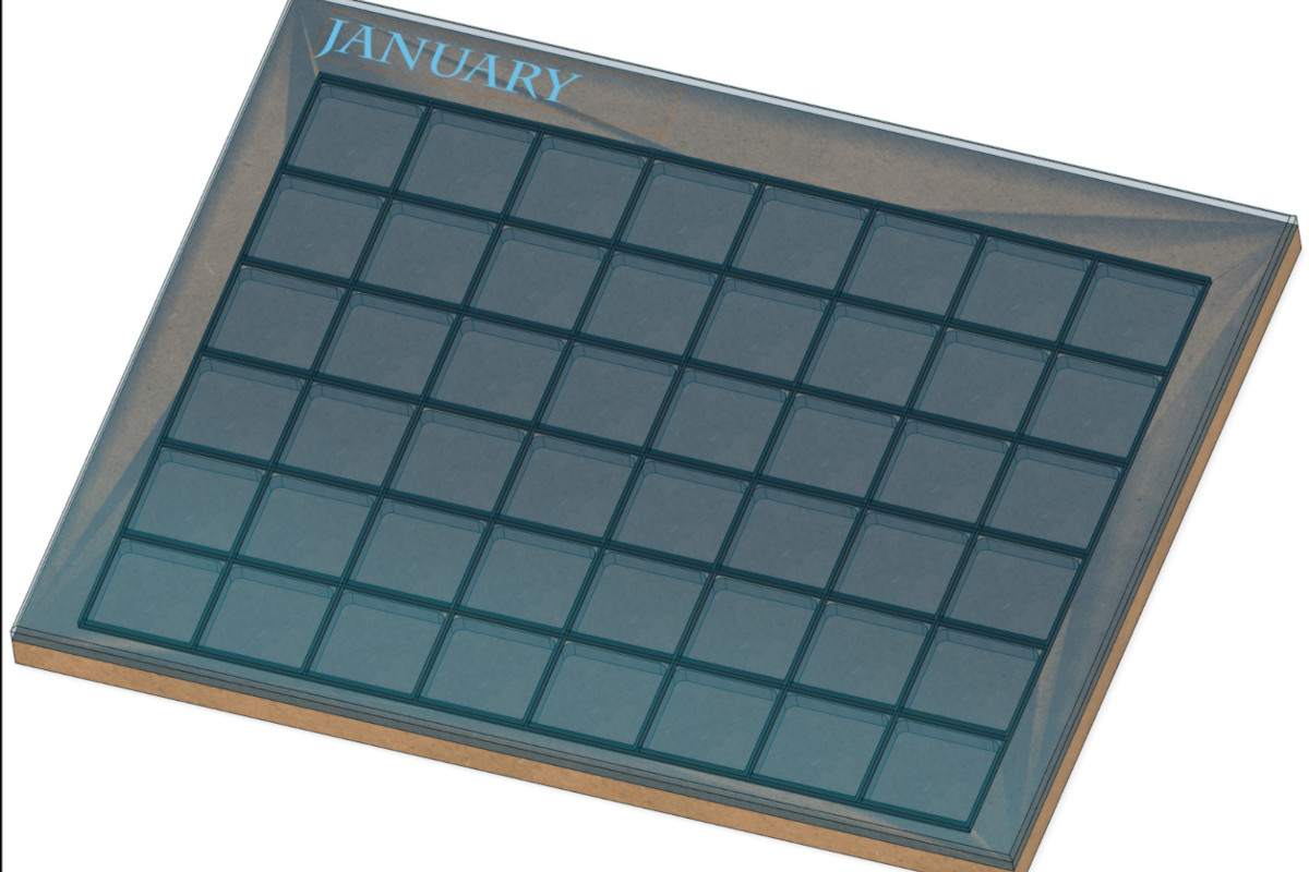
I went on from here and created the grid and the backboard for my project as well. Once each part was finished, I rendered each part through the Render option, just to get a general idea of how it may look when finished. The first issue I found was that the top surface can’t be transparent or clear. The goal is to hide the components and just have a basic board on display. Since this was a quick test, I left the glass option and moved on to the next component. I’m still not sure what I’m going to make the grid out of, but it has to be black, so I used “Metallic (Black)” under “Paint”. Last, for the base, I used MDF board, but I had to download the option as it’s not available in the default library.
I went back later and found a frosted version, both a light and medium frost, but there wasn’t much difference between the two.
Once everything was rendered, I opened the base and brought all the components together for a test fit. Fusion makes this really easy, as you can simply drag and drop the parts you want to use in your assembly. I also made sure that when I created each component, I used the same origin point, so when each part is added, their origins will align by default. This is something that can be accounted for when you’re the only designer working on a project, but when there are multiple people working on the same project, chances are that origins lining up is not a priority. There are other ways to align the parts once together.
I decided to start from the base and build the assembly on top. I dragged the grid into the design space, and it automatically lined up the origin for both parts. Then I added the main board the same way, creating the “finished” product!
Here are the links to the files for Fusion 360:
FreeCAD
I decided to try out FreeCAD.
I wanted to use my Fusion 360 STEP files, but FreeCad can’t use those files, so I had to make the base from scratch.
First impression: Where is anything?
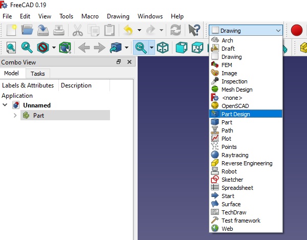
Part of this is on me, going from Fusion back to FreeCAD was bound to require a few concessions, but it took a few minutes to even figure out where the part design space option was. Then it was a hunt to figure out how to edit or even start making a part, but once I got that far, the menu bar became much more familiar. But to be completely honest, using it quickly became an exercise of patience.
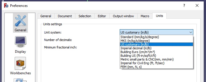
The units weren’t immediately obvious, so it took a bit of hunting to find how to change them to inches. There is a display in the bottom right that shows what units are in use, which defaults to millimeters. To change the units, I had to go to “Edit”, then “Preferences”, then in the “General” menu, go to the “Units” tab, and select “Inch”.
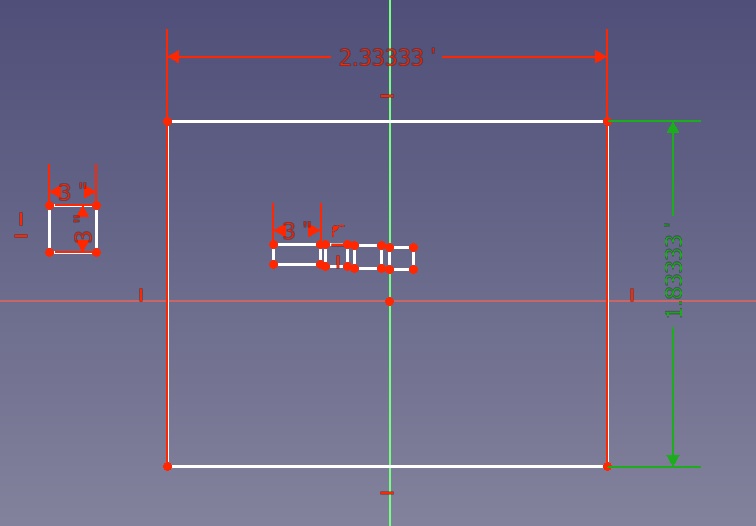
After messing around in the design space, I had a couple rectangles, but then the next hunt was finding the dimension option. For the most part, the icons across the top are fairly intuitive. Things like lines, circles, polygons, rectangles, etc., are obvious, and the more I went over the menu, the more the groups made sense, but it took me a while to find the dimensions. Every option is shown with a different icon, which I suppose works, but seemed like a lot of extra clicks to dimension the same type of lines.
I’ll be honest, I messed around with this for about a half hour, and while I see where it works when options are limited, it seems very clunky and a lot of the things I wanted to do were either buried in menus or I just couldn’t find them. I didn’t have much patience for hunting for what I wanted to do, so I’m leaving this here and moving on to another program.