7. Computer Controlled Machining
This week is CNC machining, a week that I’ve been looking forward to.
Fusion 360 again
My inspiration for this project comes from Adam Savage’s Leatherworking Toolbox. I love the design, particularly how the doors swing open until they’re completely flat, with everything easily accessible. The most difficult part for this build will be dimensions. He doesn’t give any in his video, nor could I find any online, so I played it by eye and did my best approximation. If anything, that worked in my favor, since I’ll have something that is unique to me.
Designing in Fusion
The hardest part of designing this was figuring out how big to make it, and to be honest, I made it too small. It’s very cute, but I’ll get to that. I also needed to figure out how to add the joints. I’ve never done woodworking before, though I’ve watched a lot of videos (Adam is always making boxes and cases to organizine/store his tools). I knew I would have to account for the thickness of the wood, so I made this my parametric measurement and based all my dimensions off that.
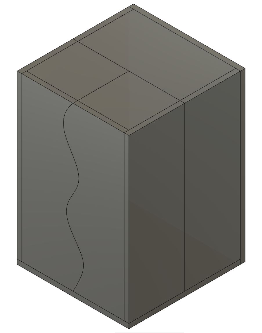
I started by designing the rough layout of the main box and the doors and added a curved feature to the front. When making this, I made sure to create each piece individually in case I needed to modify them later.
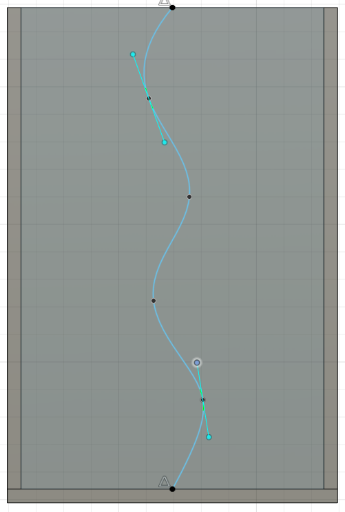
The Spline tools is basically a fancy line. You can draw and place multiple points which can then be moved around. They also serve as anchor points for adjusting the curves between each point, by moving the points on the ends of the green line that intersects the anchors.
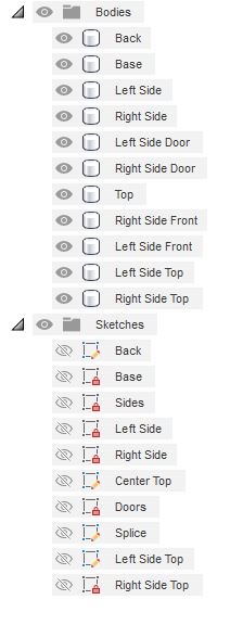
Since there were so many pieces, I made sure to keep everything labeled so I didn’t have to hunt through the files to find the one I needed.
I also wanted to show it in motion and knew some of the basics of creating an assembly, but I had never tried to animate it before.
All the bodies are still contained within the components.
First I changed all the bodies to components in order to assemble them. Then I grouped the pieces by their function, so the pieces for the left door were grouped together, the right door, and the main body. This means that those groups will move as one piece when animating or joining.
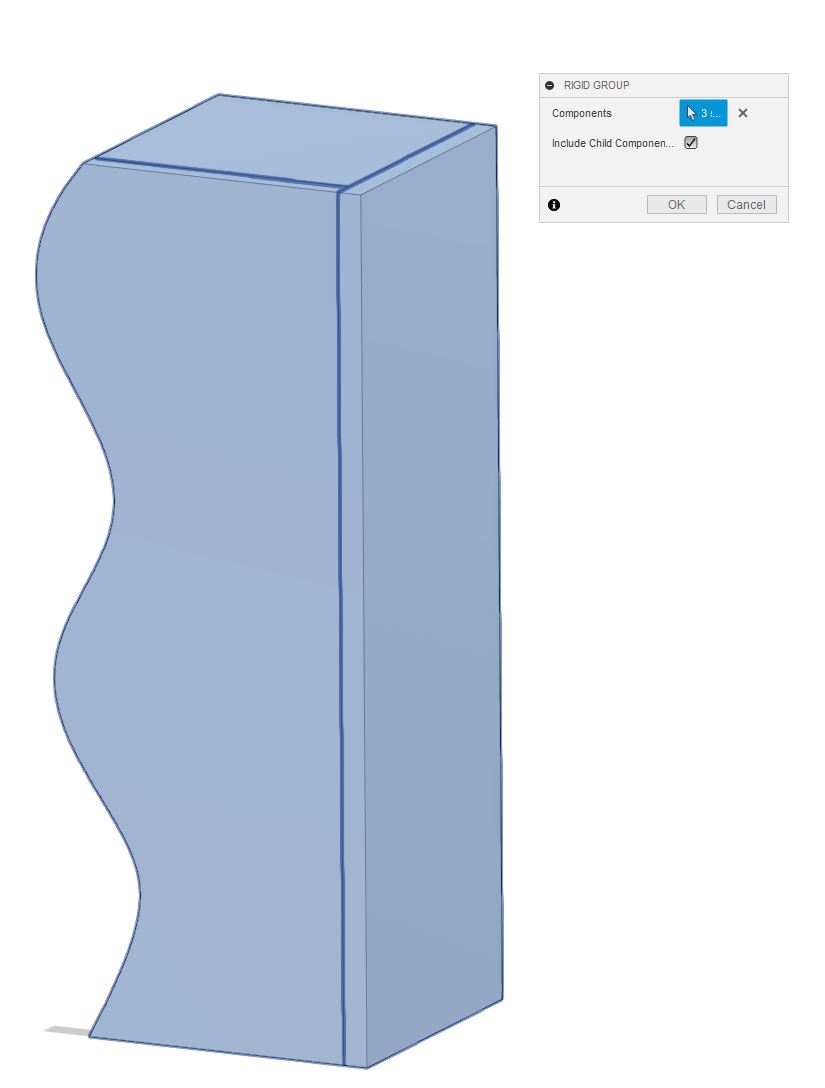
Now the pieces will move just like the actual door when I make it!
Time to Make It Move
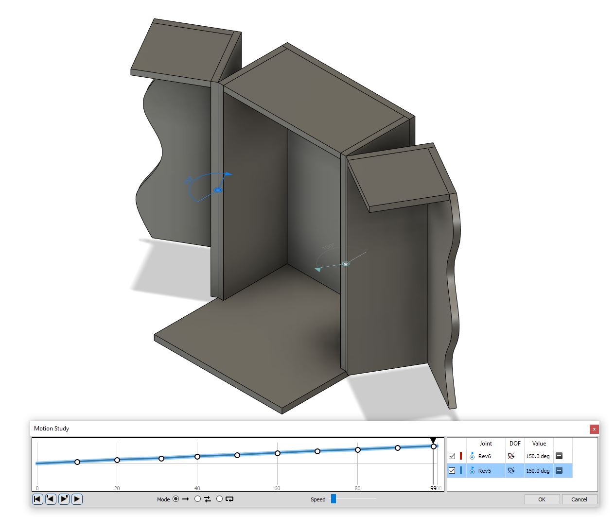
Next, I needed the doors to rotate or swivel on their axes, so under the Joint options, I selected the first joint, which is the door, then the second on the body wall. It’s important to select the components in order. The first selection is the one that moves, the second is what it pivots on. Under the next tab, I select rotate, and it showed a preview of the motion. It initially shows 360 degrees of freedom, but we can change that later. This just makes sure the correct component is rotating. I did the same process for the second side.
Then I had to edit the joints so I had the correct range of motion. I did this by going down to the timeline and right clicking the specific joint and editing the limits. I want the doors to open flat, so I set the range of motion from zero (0), when the doors are closed, to 180 degrees, completely open and flush with the center section. Now that I had my ranges, I wanted to move the doors so I would have an idea of how it would look.
Under the Assemble menu, I selected “Motion Study”, at the very bottom of the list. This will only open if there are joints in the design. In the pop-up window, there is a timeline and a list section. First, I selected the joint I wanted to animate, then in the timeline, I selected a point, in-between the first two lines marking time. I typed in the degree of motion I wanted, or how far it would move at that moment, and then selected the next point, and so on until I got to the end of the timeline. I then selected the second joint, and did the same thing. The two joints were color coded in the list, but it was difficult to see both on the timeline once I set them up. It’s not surprising given that I had them move the same amount at the same(ish) time, but it’s something to keep in mind.
Some things to note about setting this up:
- It’s extremely finicky, meaning that if I didn’t click on the exact point to change or edit, it created a new one.
- What you see is what you get. The amount of time shown on the timeline is it. It’s not very long, but it also doesn’t have to be. This is only to check motion. I didn’t realize this at first; I assumed once I reached the end a scroll bar would appear and I could continue. This also meant I had to adjust the increments of movement in order to make to the full range, which leads back to my first point.
- Do NOT press “Okay” once you’re finished. This closes the whole window and everything you did is lost. I hit this so many times while working and had to start all over again. It was frustrating to have all my points selected for both doors and be ready to record, then hit “okay” on instinct and lose it all.
- When animating multiple joints that need to move at the same or close to the same time, I couldn’t find a way to set specific points in time. Point and click gets close, but I wanted the doors to move at the same time. I got close, just clicking as close to the points for the first set as I could, but if you were trying to adjust timing, it would be nigh impossible. There may be a more exact way to do it, but I didn’t look too hard for it. Considering what I wanted, close enough worked just fine.
Hopefully it looks this good by the end.
The Next Day
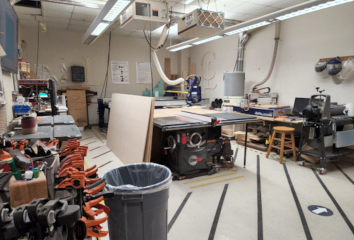
First, I want to give a huge thank you to Charlotte Latin for not only letting us use their ShopBot, but coming in on a Saturday during Spring Break. And thank you to Tom, David, and Adam for arranging it and helping throughout the ordeal (I’m not exaggerating, but we’ll get to that).
I still had to add the joints to my toolbox, and David helped give me an idea of how to add them, then it was just a lot of rinse and repeat.
There’s probably a better way to do this, but here’s how I did it.
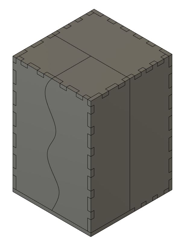
I started by selecting the edge face of a section, then created a new sketch. From here, I created a rectangle that would be the joint. I used the snap points to create the rectangle, but that created a problem. I needed to dimension it using my parameters, so i had to delete the constraints on each side. The width was the thickness parameter, in this case “d3”, then set the length of the joint. I went with 1” to be consistent and easy to remember. Then I set the rectangle 0.75” from the edge. Again, this is for consistency so I know where to start the next set of joints on the opposite side. Then I used the rectangular pattern option, selected all four sides of the rectangle, the direction I wanted them to populate, and how many. Then I dragged them down the side until they looked alright. This took a bit of playing around to get right, but once I did, I made sure to note how far they were spaced so I could match it on the mating part. Once set, I saved the sketch and extruded the joints by the driving dimension. Make sure to set the type of extrusion to “Join” and not “New Bodies”, or you’ll end up with a laundry list of new parts.
Then it was on to the mating part. This is where having each panel as a separate body was helpful. The process I’d essentially the same, except instead of extruding up, I extruded down to cut the matching pocket. If the first panel was still visible while doing the extruding cut, then it will cut through everything visible, including the joints you just made. I did this a few times before realizing I needed to hide the panel I didn’t want cut.
This took a really long time. If I do this again, I’ll find a better methodology. It’s only a matter of researching.
The last thing I had to do was convert the files to a DXF file that Aspire could then read. I learned this was possible from Aging Wheels’s video where he made a table for his new CNC router. He mentioned in the video that he exported the face of each part as a DXF.
This is the point where labeling became a HUGE help. I had tons of bodies and sketches to create the box, and at times it was a bit confusing, but I stuck with my labeling method, and it helped me keep everything organized.
The easiest way I found to do this was to hide the parts I finished.
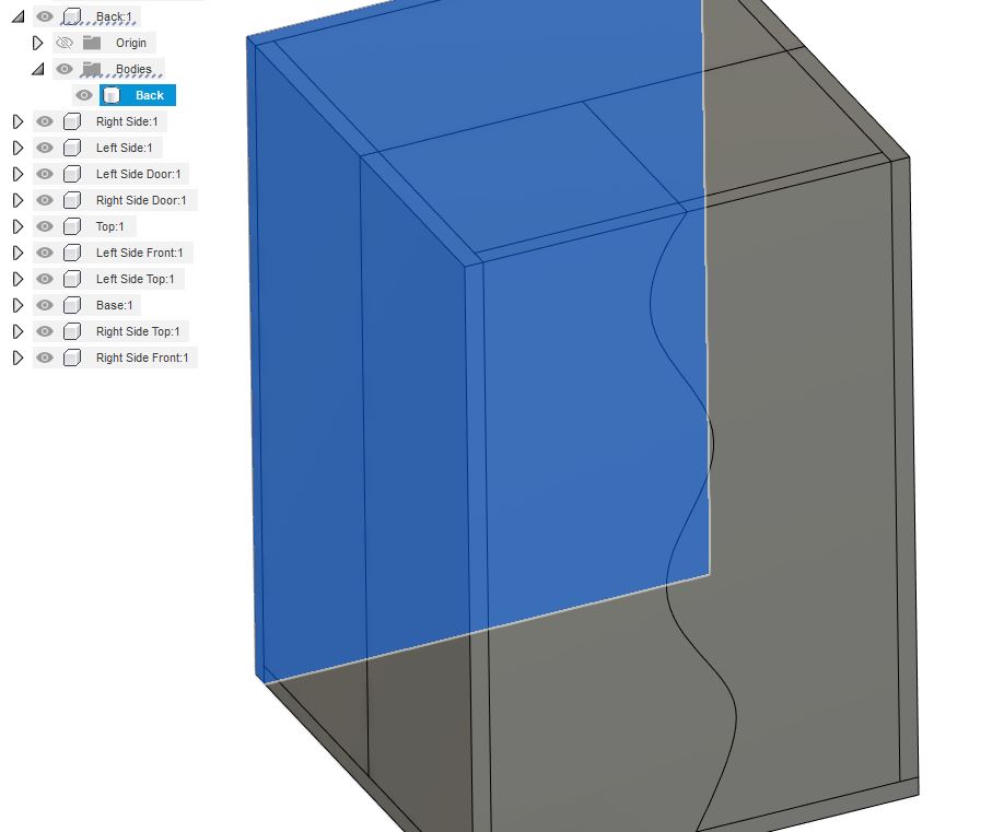
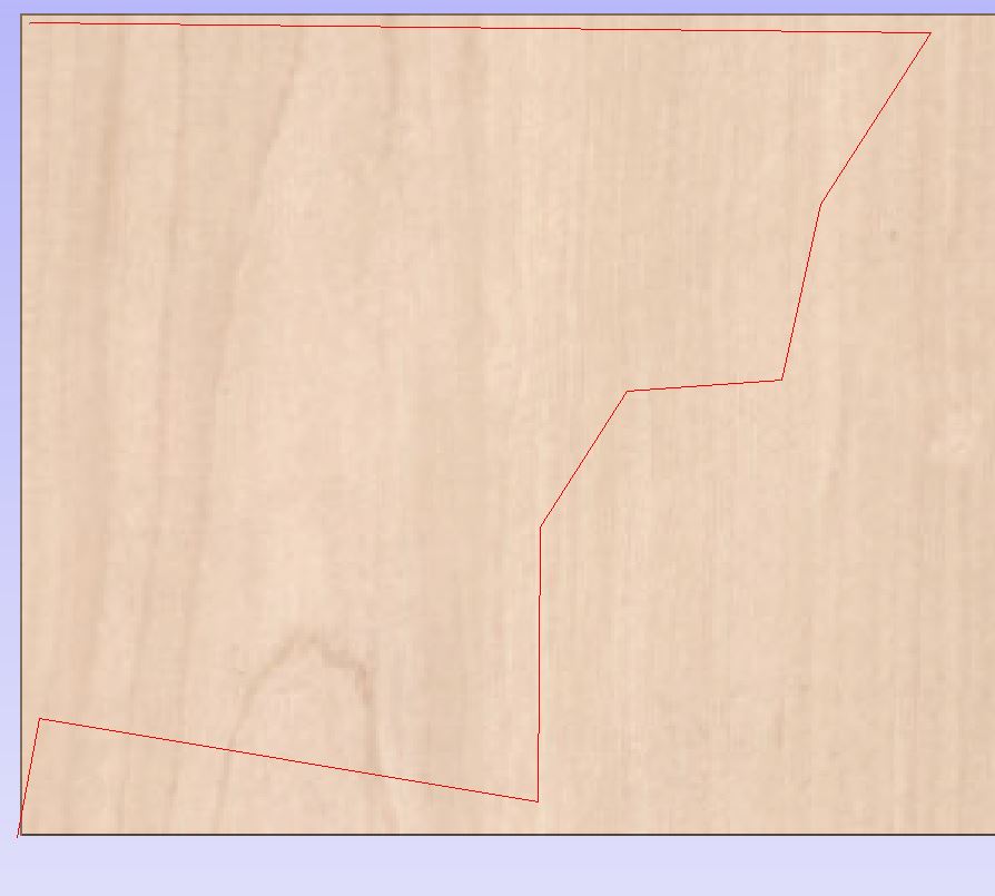
I started with the back of the main box. I selected the face that had the profile I wanted to cut and created a sketch on it. Then I used the “Project” option in the drop down menu. This projected the outline of the back piece onto the sketch plane, shown in purple lines and points.
And that’s all I needed to do. I saved the sketch, labeled it, and then hid the matching component. All that’s shown is the purple outline. I hid the sketch as well since the lines can get confusing. I did the same thing for each part until everything was hidden.
Lastly, I right clicked the sketch for the back piece and selected “Save as DXF”, named the file, and saved. First part ready for toolpathing!
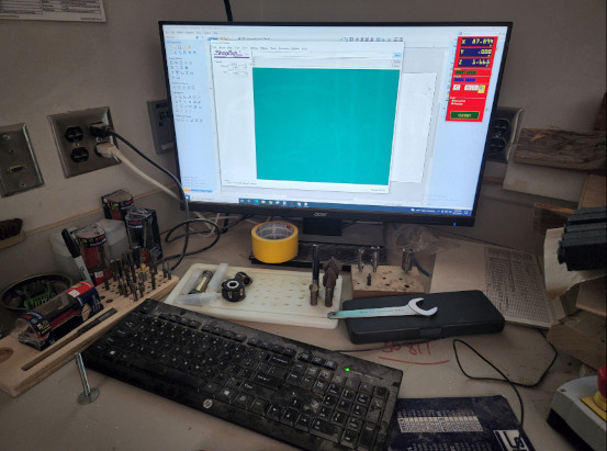
Aspire
Aspire is a toolpathing software for CNC routers. It allows you to import DXF files and modify and/or tweak them so they can cut easily with the router, then create any necessary toolpaths and export them to the machine.
The first thing I had to do was set up the work area. Initially, I was going to use the smaller ShopBot and let Garrett use the full size machine. He had more than double the amount of pieces, and they were more intricate than my box, so I figured they would be better suited for the larger machine.
Unfortunately I didn’t take very many screenshots of Aspire. Garrett has a much better overview than I got.
Importing and Arranging
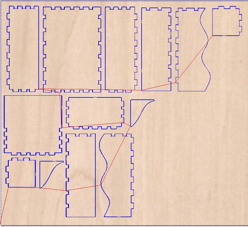
The cool thing about Aspire is that you can add in multiple files and arrange them in the workspace. You can either open the files one by one, or drag and drop them in from a folder. I had originally planned on using the smaller ShopBot, so my arrangement required three different setups to get all the pieces, but I ended up using the large one instead. This allowed me to put all the parts on the board at once.
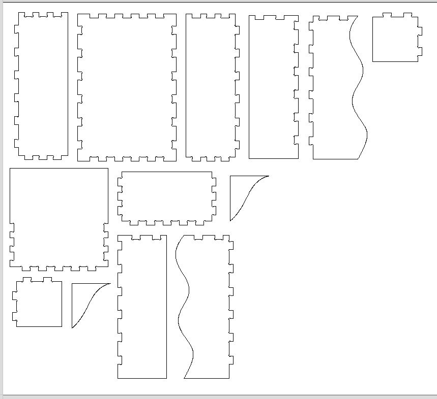
Then it was a matter of grouping them together in a way that minimized wasted space while also keeping the size of the tool in mind. I used the Move tool as well as rotate to do this. Since the tool travels along the outside edge of the actual cut, due to cutter compensation, I needed at least an inch of space around each part so the toolpaths wouldn’t overlap.
Adding the Dog Bones
Next thing was to add dog bones. Essentially, round tools don’t like sharp corners. Anywhere there was an inside corner, the tool would leave a radius equal to the cutter. The way to get around this is by adding a relief hole to the sharp corner, creating what looks like a dog bone, if on both sides, or Mickey ears. This relief is also important when trying to fit another piece in the slot that does have sharp corners. The relief allows the mating part to sit flush without interfering with the original part.
Aspire has a specific tool that allows you to set the radius and then click the point that needs the relief. One thing to note, set the radius BEFORE adding any dog bones. The only way to update them with a new radius is to delete the old and add in the new. In most cases, the radius is going to be half the cutter diameter, so if you’re using a ½” (12.7mm) cutter, then the radius is ¼” (6.35mm).
Then the real fun begins. Aspire doesn’t have any sort of detect feature, so I had to click on every single inner corner on every part. Luckily I didn’t have too many, but it was enough to be tedious, and it’s easy to misclick or skip over a corner. It’s also possible to click a corner, add a dog bone, and then misclock and remove it.
If the dog bone doesn’t work or a corner won’t accept it, that means the lines of the model aren’t connecting properly or don’t touch at all. This happened on one of my parts. All the lines looked like they connected, and even zoomed in it looked right, but when I clicked on the outline, only half the part highlighted. That means the lines were broken on either end of that highlighted section. One way to fix it is to use the “Connect” feature, which will extend the lines until they intersect, creating a continuous line. Then the part should work properly.
Toolpathing
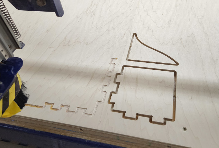
Once everything is ready on the board, then we need to set up the toolpaths that will cut the shapes. My parts were all fairly simple and I didn’t have any extra features, so I only had to do a contour toolpath to cut out the shapes.
Adding Tabs
One thing I needed to add were tabs. Tabs are how the part remains connected to the original sheet when cut all the way through. They keep the part in place so it doesn’t break free and move around while the cutter is finishing its toolpath. This is found under the Tab option. Here, you can add as many tabs as you want. The program will automatically space out the designated amount around the parts, so if I wanted four tabs, it would place four tabs around the perimeter of every part I selected. It also lets you add and remove tabs as necessary. Some of the larger pieces need more tabs than the small ones.
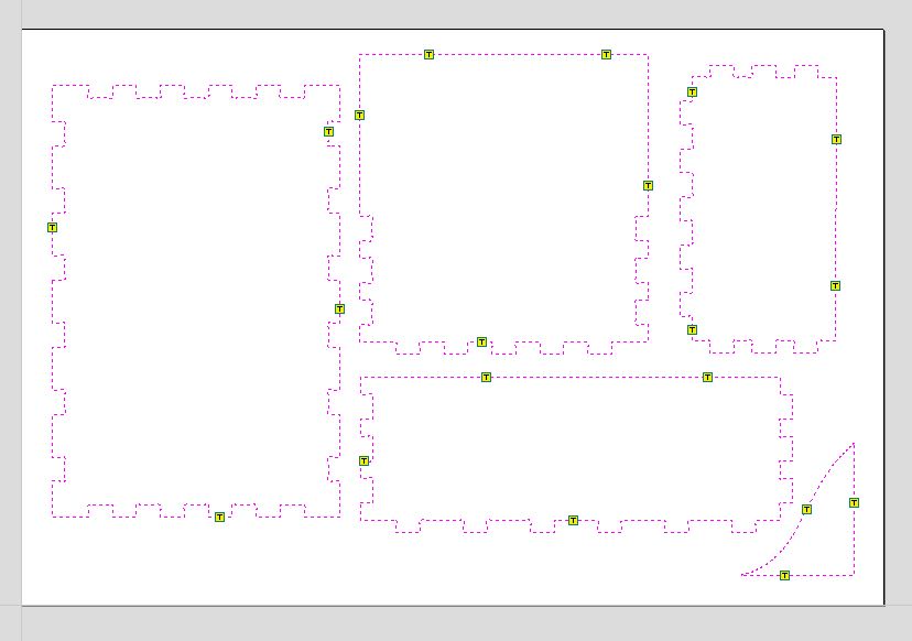
NOTE: Something to consider down the line that will make your life easier is tab placement. Don’t place tabs in any valleys or between small features. Always put them on the outermost perimeter or feature of the part. This will make it easier to remove the tabs when you’re finished cutting, especially if using a chisel, and when you’re sanding and cleaning up the parts later.
Feeds and Speeds
I’ve only ever worked with metal and plastic before this. Wood is completely different and behaves in ways I can’t expect. To me, it would seem like the plywood is soft enough to run at a decent speed, but I also didn’t want to break anything, so in the end, we decided to run at 100 IPM. From what I understand, Tom has some presets in the computer already that he uses for the students, but we weren’t aware of that until later. (We also learned later that 100 IPM was slower than what they usually ran, but when we gave them a number, they couldn’t say if it was too fast or slow, so 100 sounded reasonable and worked for us.)
Generate the Path
Name Your Toolpaths
One thing that Tom emphasized while setting up and saving the toolpaths was naming them. In general this is good practice, especially in the industry. It makes it easy to find specific toolpaths if something needs adjusted, and lets the operator know what to expect from the toolpath as well. For example, a program could have three different contour toolpaths in a row that all do different things. A label tells someone what each specific path does, so the first one can be called “Boss Contour” if it goes around a certain feature, then the next can be “Top Step Contour”, then “Second Step Contour”.
It’s also extremely helpful when you need to go back to an older program. It doesn’t take long to forget what a specific path does, especially if you’ve done multiple parts since then. There are other instances where a program may have one toolpath, but it was created to machine a specific tolerance for a feature. On its own, it may not make much sense, so having it labeled correctly will help down the line as well. Usually those sort of programs are there for a reason, but they don’t do you any good if you can’t remember why you made it in the first place.
Luckily for me, as I mentioned before, my parts were all fairly simple, so I just needed two toolpaths, one to mark the pilot hole locations for the screws, and a second contour toolpath to cut the pieces out.
Saving Together or Individually
Normally when a program is written, the toolpaths are saved as one whole program, since every path there is necessary to create the part. However, sometimes it’s better to save the toolpaths as individual programs. This is the case if something needs to be done in between paths to prepare the part for the next step on machining.
I saved the drilling and contouring toolpaths separately. I needed the drilling path to mark the holes. Once finished, then I can put the screws in to fully secure the board to the table for the main event. In this case, it makes more sense to keep them separate.
There is a code in machining called M0, which tells the machine to stop what it’s doing and wait for someone to press “Start” again. Then it continues on with the next bit of code until it encounters another M0 or the end of the program. It’s very useful when a part needs to be checked or a fixture needs adjusted in the middle of a program, but not so much when a lot of work needs done. It’s more of a pause than a full stop.
Setup
Before we used anything in the shop, we went over the safety rules and work overview. It doesn’t matter what kind of shop you’re in, whether a machine or woodworking. The same safety rules apply: safety glasses, enclosed shoes, ear protection, and in this case, a mask as well for any dust.
Materials
- 1 Sheet of plywood
Tooling
- 1/4” 2 Flute HSS Endmill, Upcutting
Feeds and Speeds
- 100 IPM (Inches per minute)
- 16000 RPM (Revolutions per minute)
Trouble with the ShopBot
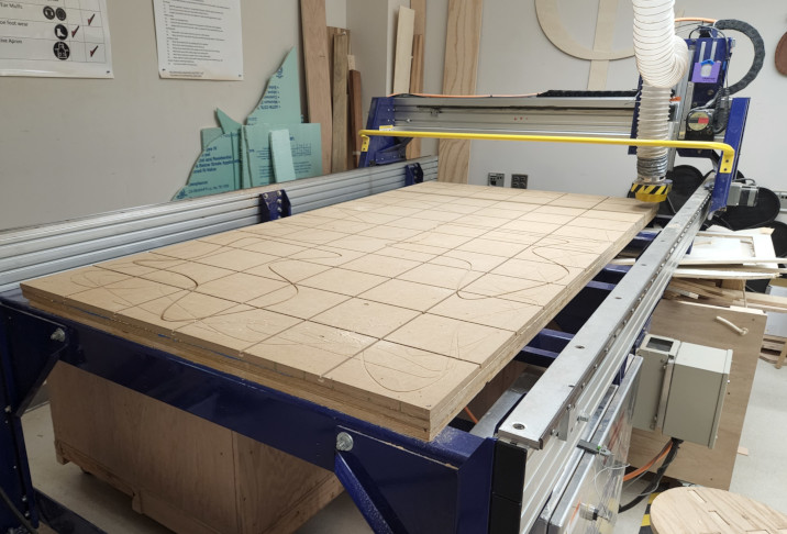
At this point, Adam, Garrett and I were on our own. And this is when the problems started.
First of all, when we tried to move the spindle around with the jog tool, the program would freeze. It would start moving, then just stop.
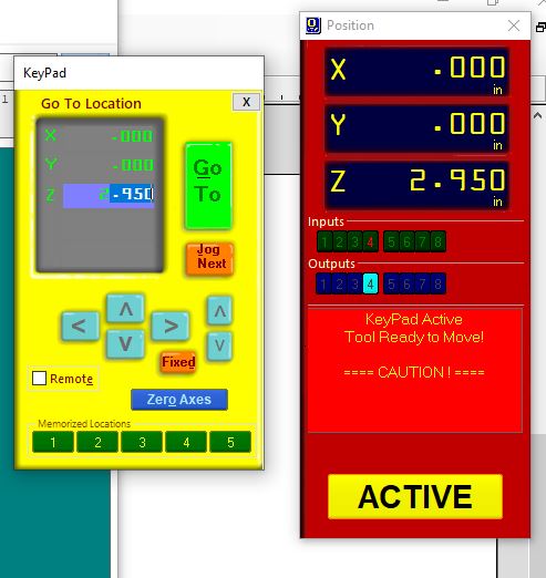
When in the hand movement option, can use the keyboard to edit in the green box, then hit enter and it runs.
This happened while we were moving it to zero the Z axis with the plate. When we finally got it where we needed it (after force closing the program) it would freeze halfway through reading the script before moving the spindle. The initial fix was to force close the program and try again. It worked the second time, but the problem happened again when we tried to set the origin for X and Y. Again, force close and it worked the second time.
Each time the program reopened, it saved the last position, which was the one saving grace, but it was extremely frustrating when it had worked earlier in the day. Later we learned that the machine does not like moving with the jog tool, which is a huge flaw with the software. Being able to jog the gantry is a fundamental aspect of using a CNC machine in general.
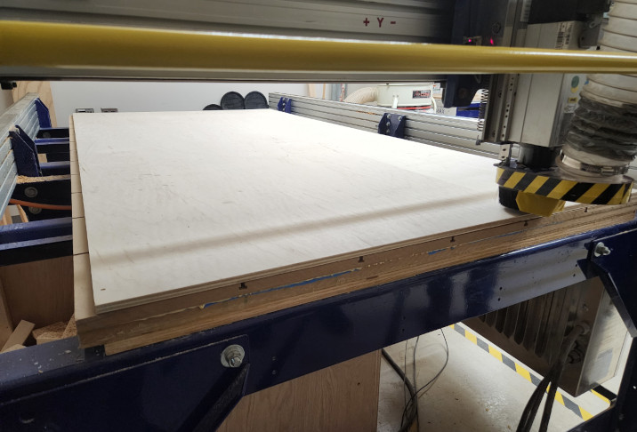
Once we got the Z height and the origin in the X and Y set, we were ready to start cutting.
However, when we tried to run my first program to drill the securing holes, the spindle would not turn on. The green button did not work, even after checking that the interlock was engaged. Because it couldn’t move on, the program froze again. This time when it came back, the Z was 1” higher than it was before. I believe this happened because it set the Z height exactly one inch higher. Eventually we had to restart the computer and try again.
This time we ran it in the air and it worked, but it was moving quite slow and it made an awful sound when moving diagonally. We had been told initially that the machine made some noises, but this was really concerning. When we asked, it turned out the travel was set much slower than normal and the jittering sound may be due to it moving so slow.
Again, we found out later that when air cutting, we cannot start with a tool higher than 4 inches in the Z axis, or it has the potential to hit the limit stop, then it freaks out. They usually set the height to 3 inches to prevent any problems.
When I tried to start it up again after this, we found out that ShopBot doesn’t have another basic CNC function: Returning to the home position before starting. The gantry has to be moved back manually before running a program.
The easiest way to do this is with keyboard commands entered in the command line at the top of the program screen, basically selecting the options from the menu across the top. To move back to origin, hit [J] for Jog, then [2] to move both X and Y, then [0,0] to return to the zero location for both axes, then hit enter.
Another thing we were concerned about was how hard the gantry hits the limit stops when returning home. According to one of the teachers who does the maintenance, they’ve asked ShopBot about it and have been told it’s normal, but hitting with that much force every time can’t be good.
Is very counter intuitive, needs better software for sure. While there, I talked to Nidhie about her experience with the ShopBot, and she said it took her three hours to set up a simple test cut.
I thought that was an exaggeration. It was not.
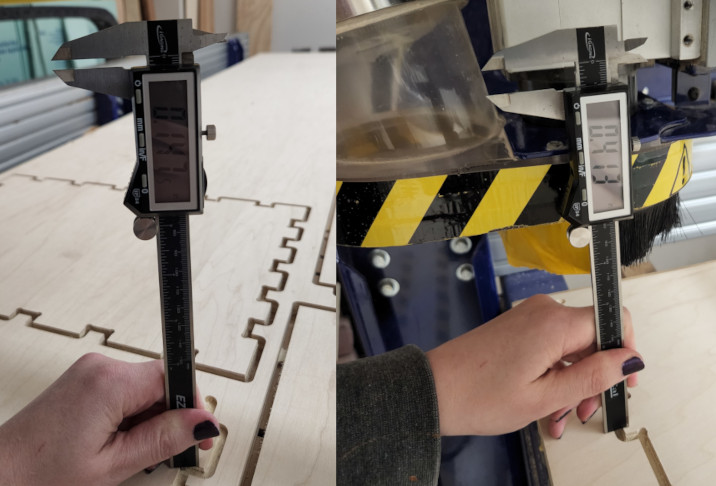
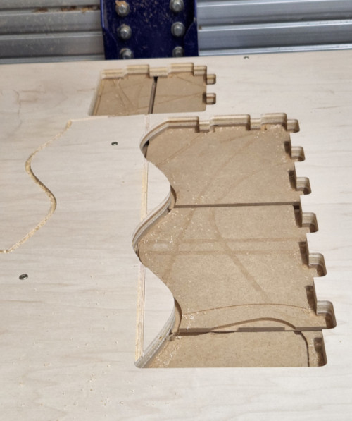
Finally, FINALLY I started actually running my program and it ran beautifully, but it didn’t go down to the total depth. The first cut was quite shallow, then the final cut didn’t go through the material. We couldn’t find any good methods to fix this since the board had been screwed down. We decided to raise the Z height .05” then drop the tool down to the 1” block. So the tool is longer than it thinks and hopefully that fixes the problem. It did not.
We ran it a third time and the Z was cutting at -.150” and it still did not cut through.
Also at this point, the crunchy sound when it moved diagonally was back.
By this point, Tom took over and tried to correct the issue and we kept running into the same issue. It kept staying above the bottom. Eventually, we had to tell it to cut 0.7” on a piece of wood that is 0.5”, and it barely scratched the surface of the waste board.
We popped out the first piece and decided to rezero again. Then we reset the depths so it would cut down to 0.51” with five step-down passes and it finally started to work. By this point we had spent over five hours trying to troubleshoot everything.
At this point, the machine cut pretty well until it got to the front left piece. A big part of machining in general is sound, and the toolpath started out okay, but quickly got louder and more grating and I immediately stopped the machine.
The tool was getting sucked out of the collet. Our first thought was that the nut was loose, but it may have loosened over the course of the vibration of the cutting until it was loose enough to move.
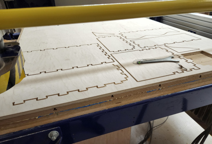
We moved it back to zero and retightened the tool and re zeroed. At this point, we removed the cut pieces. Some of them had cut through just fine, but others, specifically close to the screws, had not cut through completely. We’re not sure why it happened where the board was secured the most, but we were able to chisel or cut the parts out.
Then I modified the toolpath to remove the pieces that were already cut and started it up again.
This time it made it to two parts before we had to stop it again, this time because it had sucked the tool down enough that it dragged across the surface as it moved between parts.
There was a serious problem with the collet and toolholder, and when we took it apart, it became obvious.
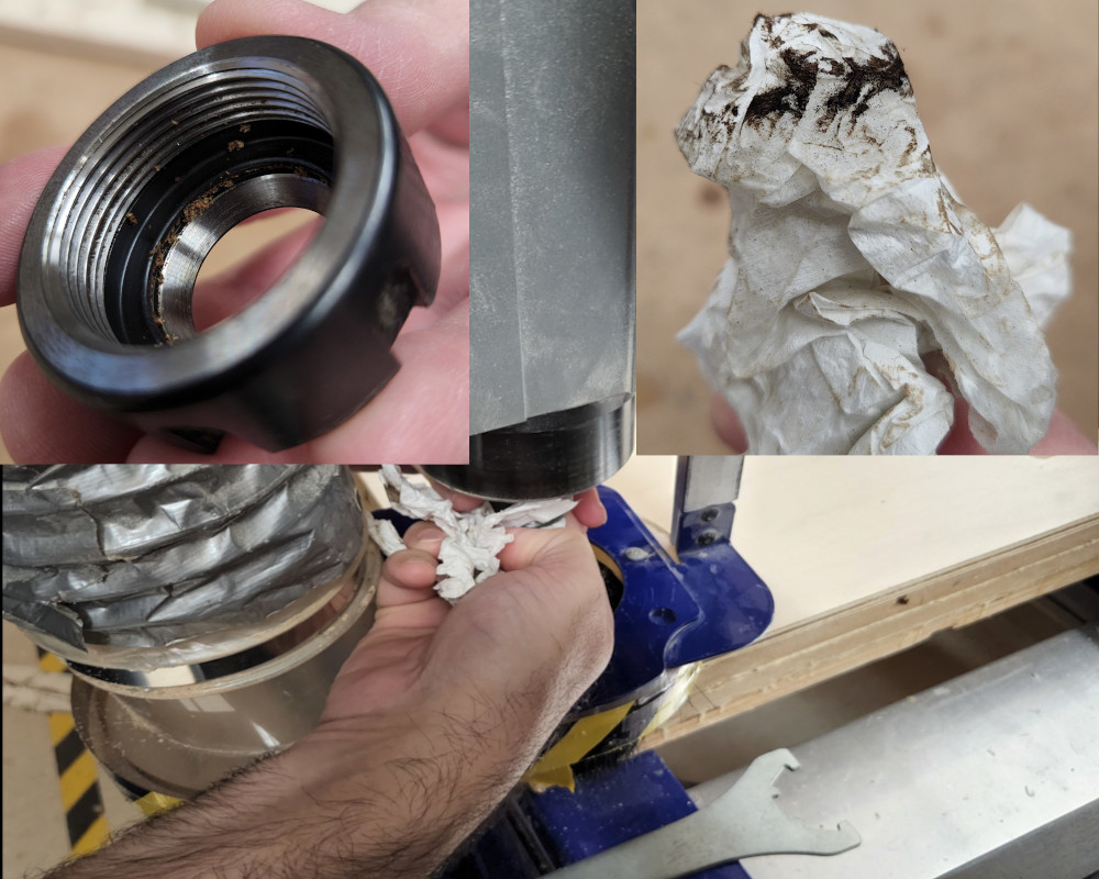
The collect was packed with sawdust, so it wasn’t actually tightening, but instead compressing the chips. We took it apart and began cleaning that out. Meanwhile, we also cleaned out the spindle, which was caked in more fine dust mixed with what could have been pitch from the wood or some sort of moisture. The inside was black and took multiple rags to clean out. Then everything was oiled and put back together.
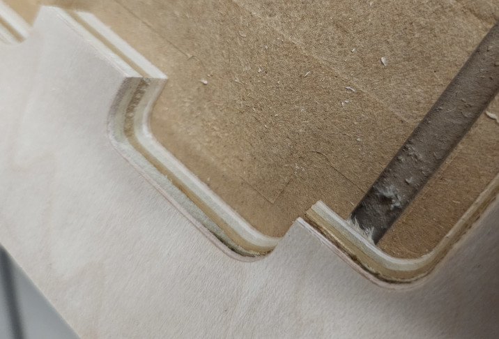
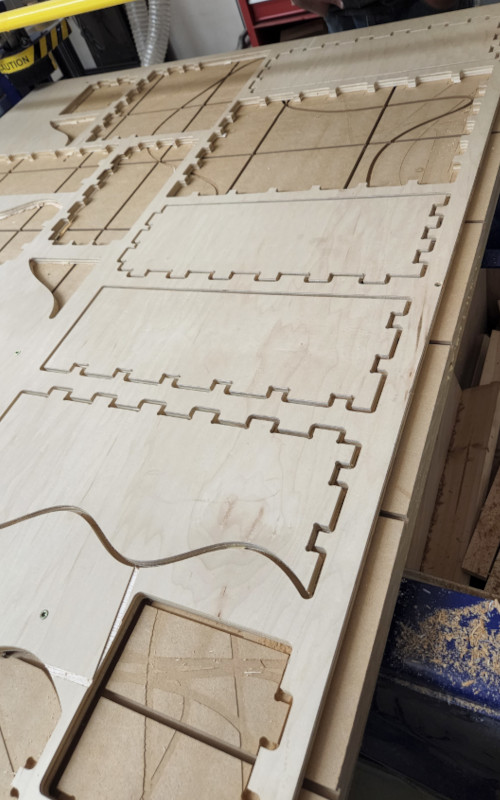
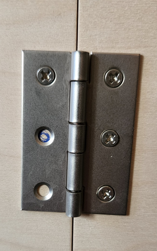
Again, I modified the toolpath to remove the pieces that had already been cut, then loaded it again. After zeroing and moving to home, the difference in the pieces was like night and day. The cuts were much cleaner, the depth was consistent and the tabs aren’t ripped across the surface. The plywood didn’t split apart either.
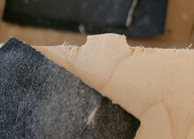
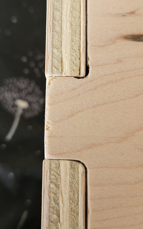
Moral of the story: Clean your equipment!
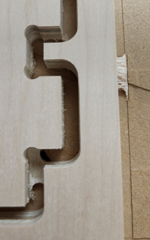
The tab on the right is from the first part I cut. It’s splintered and rough across the top. The tab on the left is from the last part cut after we cleaned the collet and spindle. The cut is smooth and nothing is split or splintered.
At this point it was almost 9 pm. We had spent just shy of 12 hours working on my project, and I really appreciate the help from everyone to get this far.
The Next Next Day: Sanding
First thing to note, placement of tabs. Doing this again, I would make sure to put the tabs on the outermost edges of the piece, meaning that the tabs that generated in between the joints, in the valleys, were a pain to clean up. Luckily I had designed the joints far enough apart that it wasn’t too much of a hassle to get in between and sand, but it would have been easier and faster if they had been on the outermost edge.
Every now and then, I didn’t remove a part correctly, meaning I left the tab on when I used the chisel to remove it from the board. I paid for it in time spent sanding each one off by hand. Luckily, it only happened a couple times.
That being said, I loved this part of the project. I love working with my hands and it was almost relaxing to sit and sand while watching videos on the TV. It was also nice to watch Adam Savage work on his projects while doing mine.
But it also took all day to do. I live in an apartment and don’t have access to power tools (if I did my neighbors would hate me), so I did everything by hand.
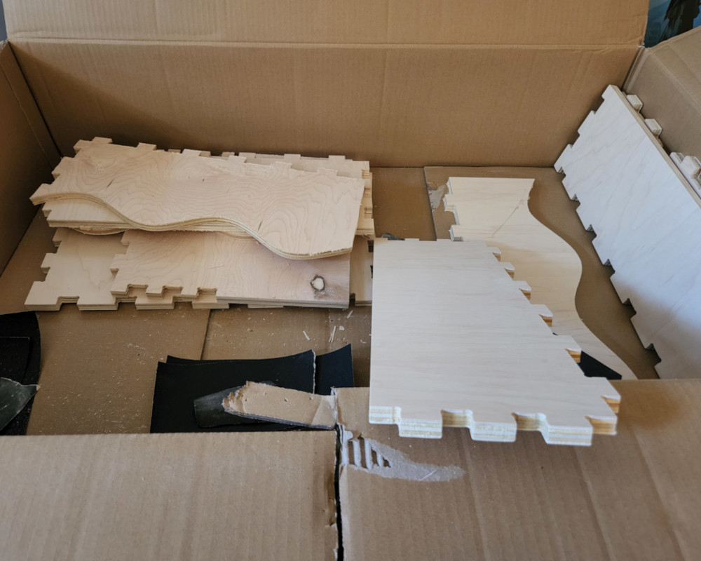
This was my basic setup for the day, a big box, TV, and lots of sheets of sandpaper. Oh, and cats to keep me company. Always important.
I had some sandpaper already to clean up my 3D prints, so I used what I had left. I got most of the rough edges, and the tab remains off with 180 grit, then moved to 240 to remove any fuzzy places. I only had one strip of 320 grit, and I used it to finish just over half of the pieces, then I had to use my 400 grit. From what I understand, this is more fine that what most people would use for wood, but it left a wonderfully smooth surface.
Super satisfying.
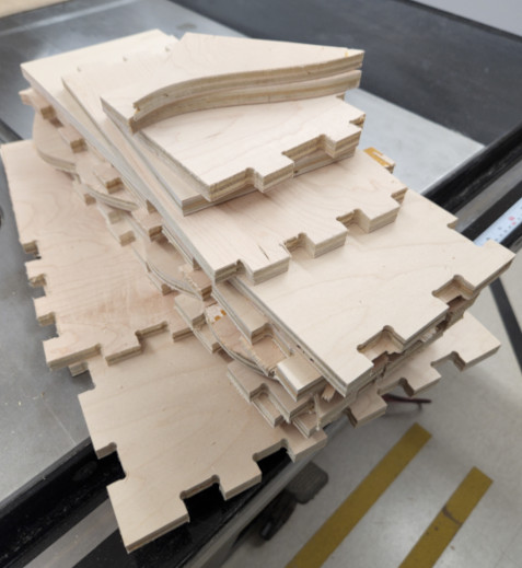
After 6 hours of sanding by hand (with breaks in between) I finally finished everything and was ready to assemble. I put the doors together first because I really wanted to see how they looked together.
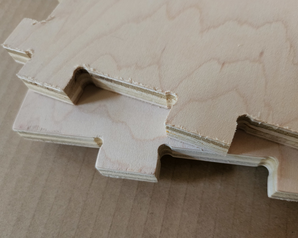
They looked amazing and went together almost perfectly. One side was a bit more loose, but that’s probably due to sanding than the cuts. I did notice I had two corners that did not get dog bones added. Clearly I missed those, so next time I’ll double check more thoroughly. It wasn’t difficult to correct; I simply sanded a radius on the corner of the mating piece and they fit just fine.
I almost like how that looks more than the dog bone. I wonder how much work it would take to make that finish. If I made this again, I’d only have to put a radius on one side. Hmm, things to think about.
The main box was very hard to get together. Each piece required a lot more sanding to get the tabs to fit together. I ended up getting them started, then hammering them into place. My downstairs neighbors definitely hate me. I did most of it on my balcony, but apologies to them!
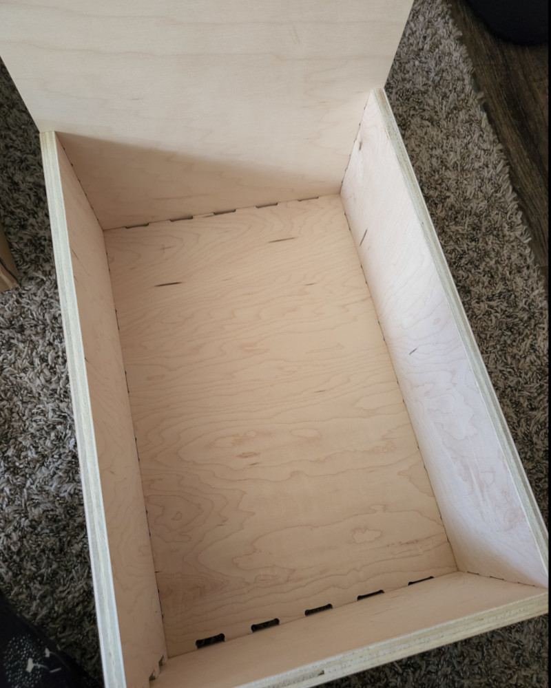
BUT finally, I got the pieces together, and if I had used glue, the main box in particular would never have fit, not without heavy modification. I don’t have any wood glue on hand anyway, so I had to make it work. As it stands, the main box is not coming apart anytime soon.
I had some “help” from Donut.
Assembly!!
Once I had all the pieces, I had to figure out how to assemble the hinges. I had never put hinges on before outside of IKEA furniture, though I doubt that really counts. The hard part was getting the doors to line up properly and held in place while I drilled the holes and screwed them in place.
Trying to figure out how to keeping everything straight.
After some headache and head scratching, I managed to get the first hinge on!
First hinge!! It’s a touch crooked but it’s on! And it hinges! I had a hard time figuring out how to keep everything lined up straight, and after opening the first side after getting the hinge screwed down, it became quite clear how crooked it was.
For the next door, I decided to tape it in place. I closed up the first door and “closed” the second door in place, then I took a LOT of masking tape and taped it so it wouldn’t move. This method worked pretty well in keeping the parts stationary while I drilled the holes. This also let me stand the box up so I could get more leverage to screw everything in place.
And now for the........
Results:
To preface, I started this build with the intention of making a toolbox. However, now that I have it together, I think I’ll make it a display case for things I’ve made during my apprenticeship. I plan on adding custom shelving and holding for each piece in its own place. I thought about making them from acrylic or more wood, but then I remembered that I’ve wanted to try 3D printing with wood filled filament. Then I can design perfectly custom holding and then sand and finish the prints to match the box.
But enough about that, how about a reveal!
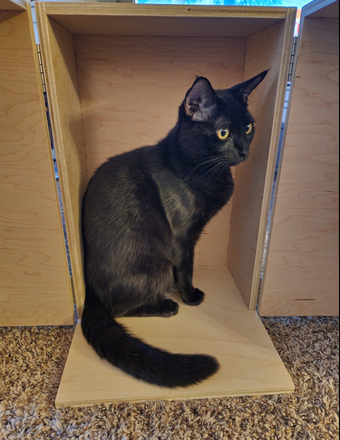
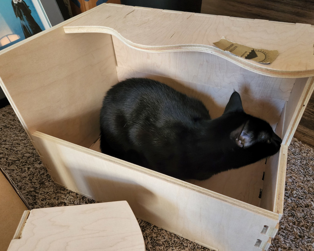
Cat approved! I’ll take it.
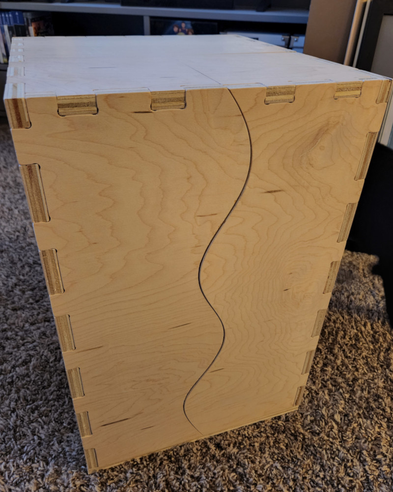
I LOVE how the box came out!! The wood is much nicer than I expected once sanded. I thought about painting it, but now that I’ve seen it, I think I’ll just stain it and leave it at that. Despite it not quite turning out the way I expected, I’m very proud of my finished product.
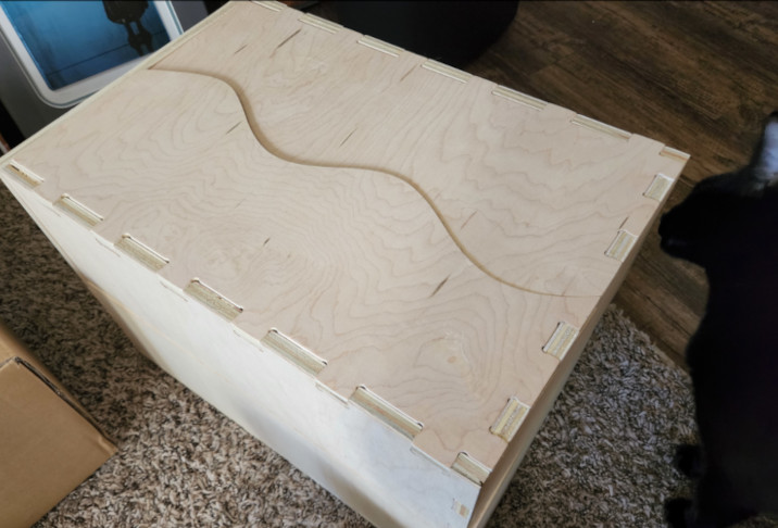
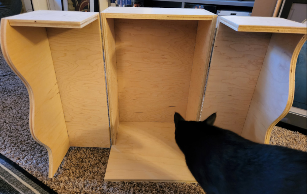
My favorite feature is the wave for the doors. They fit together almost perfectly and are quite satisfying. I may add a small magnet later so they close more firmly, but they stay in place on their own rather well. I also like how the base extends out under the doors, so it creates a wide open space when the doors swing open completely.
10/10 Would make again.
Group Project
This is something we’ll have to revisit. Due to our time constraints and how much time was spent troubleshooting to even get one project done, we didn’t have time to run anything that would characterize the ShopBot. However, Charlotte Latin, Tom and David, were kind enough to extend the invitation to come by again.
Update: We weren’t able to get back to Charlotte Latin, and their ShopBot was tied up with other students projects and classes. Instead, we decided to test the runout on one of our CNC machines in the machine shop. The full writeup can be found on our group site.
Files
Below are the files for the project:
- Fusion 360
- DXF Files
- Aspire Files
- Shopbot Programs