Prototyping Phase
Here’s where I’ll keep track of all the prototyping I’ve done to solve different aspects of my project.
Question One: Spacing
The balance I need to strike is how far the pockets need to be in relation to each other versus how big the overall board will be. I also need to take into account how I will separate the pockets, or create that calendar look. That space will determine which materials I can use as some will require more room to work than others.
Channels and Silicone
The way I have my project modeled currently, there is not much space between the pockets, which looks pretty nice, but makes it hard to figure out what material would be best to put between the acrylic and the plywood to make the black lines. I thought about creating a channel that I could then pour a silicone gasket. However, the spacing is too narrow for that, so I decided to make some spacing tests and cut them with the laser.
The space between each pocket was originally 0.2”. I decided to increase the space by increments of 0.1” up to 1”. The other thing I have to keep in mind is how much this will increase the overall size of my board. I don’t want it to become so large that it’s unwieldy.
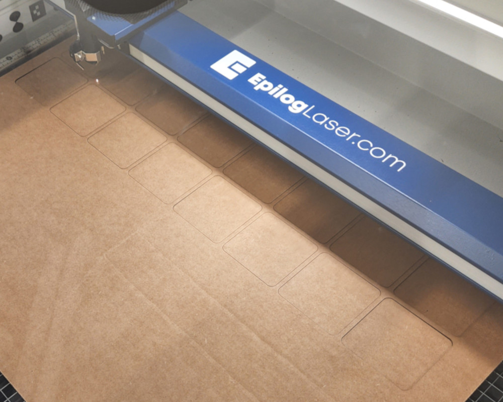
I started with my original spacing to have something to compare my tests to.
The 0.5” spacing looked the best in terms of room to potentially cut a channel and in keeping the overall size reasonable. But the more I thought about it, the less I liked the idea. There’s a lot that can go wrong when you start cutting acrylic, and given how big the sheet already needs to be, I don’t want to risk it cracking or breaking while trying to cut this channel.
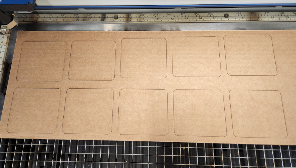
I did a variety of spacing, increasing the space in increments of 0.1” each time.
Plus, when comparing the various spacing, I like the original a lot more, which brings me back to my original problem.
Felt
I ran across this by accident while looking for laser cutting settings for acrylic. Epilog has a page on their site dedicated to sample projects with a wide range of materials. While scrolling, I came across felt. It’s easy to work with and comes in a ton of colors and sizes. There are also a couple different types to choose from, including 100% wool and polyester.
I ordered a multicolor pack of the polyester felt from Amazon to test. I figured if I end up not using it, I can at least use it for other projects later down the line.
The felt cut great with the laser, and the edges were slightly melted, leaving a clean line. The black looked great behind the frosted acrylic I had as well (more on that in the acrylic section). I cut out the white as well to use in the lighting and diffusing tests.
I like the look of the felt, but I’m a bit concerned I won’t be able to find a piece big enough for the area. I also don’t think the laser cutter is big enough to cut it out in one go; I would have to do it in sections. It’s entirely possible, but I’d have to glue them together somehow and if the edges don’t align just right, it will be very obvious. I’d like to avoid that if I can.
Vinyl
The other option I thought of was to use vinyl. I’ll have to double check, but I believe the vinyl cutter is wide enough to accommodate the height of my calendar. If that’s the case, then I can cut the grid for the pockets as well as a border for the rest of the area and use that to cover the entirety of the calendar.
This also opens up the possibilities of creating customized borders and colors for future iterations. It also allows me to add the wording for the days of the week, the notes area, and create a space where the month will be written.
The main issue is that I’ve never cut something that big before. I also have to make sure to line up the black grid and words with the border color so everything lines up when it comes time to lay it down. I’m not concerned too much about bubbles (though I’d like to avoid those as much as possible) as most imperfections should be hidden by the frosted acrylic. The main issue is alignment. I’ll have to come up with some way to ensure the best alignment possible when laying it out.
Question Two: Pockets (Depth and Diffusing)
The depth of the pockets is a huge controlling factor in both how thick the base needs to be, as well as how well the NeoPixel light is diffused. It’s also a weight issue since I want to mount this on the wall. If it’s too thick, then I’ll also have to consider ways to reduce the weight, either by milling out additional pockets or changing the material used.
I would like to stick with plywood as it’s relatively easy to cut and clean up, and isn’t terribly expensive (it is, but relatively speaking of course). The standard thickness for plywood is ½”, though I did find one that was ⅝”. In any case, I decided to create mockups to check the pocket depth as it relates to diffusion.
I want the light from the NeoPixel to diffuse as much as possible in the pocket. The easiest way to do this is to set the light as far from the diffusion source as possible. Easier said than done, in this case. The other option is to use multiple NeoPixels, which isn’t impossible, but adds that much more time and work, and increases the amount of power necessary in the long run. Both issues are solvable and manageable, but for the sake of simplicity, I’d like to minimize the number of NeoPixels per pocket.
Cardboard Pockets
I started by creating mockups of the pockets using the laser cutter and cardboard. I cut out 8 bases and then cut out multiples of the “walls”. Each base is labeled 1 though 8, and each number represents the number of cardboard wall pieces.
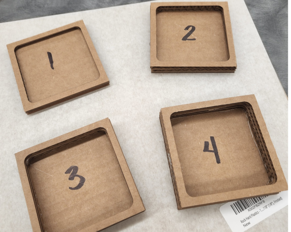
These were assembled using a hot glue gun, but after assembling the first sets, I realized I needed a way to thread the wires into the pocket so I could power the board I was using with the Neopixel. I ended up only using #4, one, due to the headers being so tall with the wires, and two, anything more shallow than that wouldn’t have done anything to diffuse the light.
I bought squares of acrylic with different finishes/types to see which one is the best to diffuse the light. I wanted a frosted look on the front, but wanted to also check what other options I had, just in case.
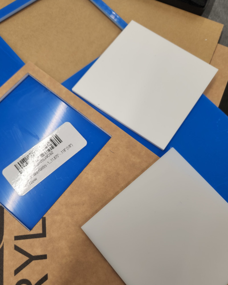
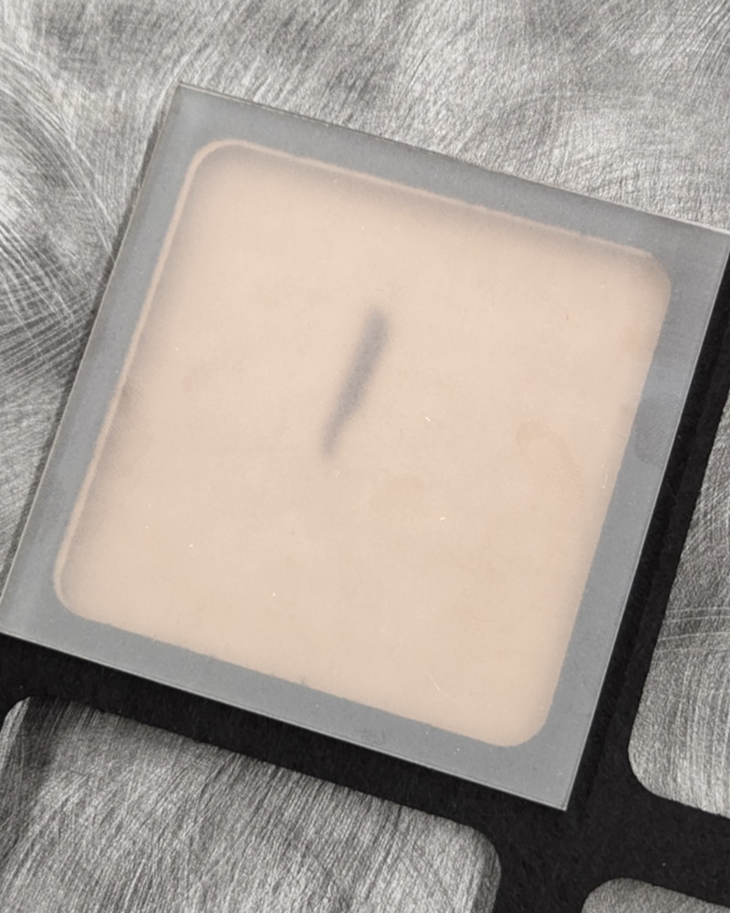
I cut each one with the laser cutter to fit on top of my pockets, and it was very obvious that my original idea was the best choice. The two “white” options had vastly different ideas of what white actually looked like. The clear acrylic surprised me; I wasn’t expecting it to be crystal clear, given how cheap it was. I plan on using the clear squares to test various frosting methods to see which one diffuses light the best, but I’ll go into that more below.
The frosted acrylic was alright, but didn’t diffuse the light like I wanted. Granted, I had a less than ideal test setup, as I mentioned before. The wires were taller than the pocket walls, so I couldn’t lay the acrylic flat to really see how the light reacted. I was able to try a few different methods though.
Ideally, I want one NeoPixel per pocket. However, it looks like I’ll need multiple in order to light each square evenly. That brings up positioning. Should I put four per square, one on each wall? Or should they be in the corners? Maybe I need one at the top mounted to the side, so the light shines into the center of the pocket rather than up. What about doing three instead? The button is going to take up one corner, so I’ll have to find another way to shine the light evenly.
If I decide to mount anything to the sides of the pockets, how will I mount them? How much more work would that create per pocket? I have 48 total, so multiply that by 3 or even 4, and the number rises quickly.
What about brightness? The board that I used had the NeoPixel brightness set to 85, or roughly ⅓ of what’s possible. If I lower the brightness, will it make it easier to diffuse? I also don’t want to make it so dim that I can’t see it during the day.
There’s still a lot of testing to do.
Pockets with Slots
For my next round of prototyping, I added a slot in the walls of the pockets so it would be easier to connect the wires to the boards. This is also in line with how I plan on actually cutting the board once I get the details hashed out. Each pocket needs to connect to the other, both up and down and left to right. I’ve redesigned one of my boards to use for this that has the headers coming off the side instead of straight up.
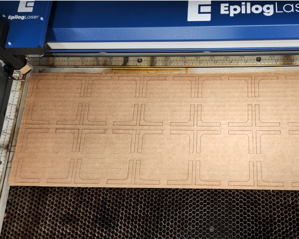
This time I used bases 5, 6, and 7. All of them use a mix of the original solid walls and the cut pieces. These pockets are deeper than what is available with plywood, but there is the possibility of stacking one sheet with a thinner piece to get the desired depth, but again, I have to consider weight.
Question Three: Acrylic and You
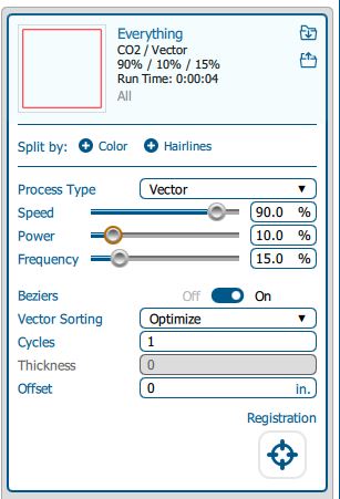
Then had to cut the acrylic squares. Looked up the settings on Epilog’s site, under their samples page. Also checked in the manual that came with the printer. Has a chart with their recommended settings for different materials.
Immediately realized there were two variations that weren’t going to work for diffusing the light. One was the 32% transparent, which looked completely white, and the other was the white, which looked slightly transparent. The clear acrylic obviously didn’t diffuse any light, but I want to cut out a few more squares next time and try different sanding techniques on them. There’s also a frost finish that can be sprayed on as well.
That left me with the pre frosted acrylic, and I was disappointed with the amount it diffused. First off, I started with the number 4 square, simply because of the connections jutted straight up on my test board. I needed the room, and even then the board, when hooked up to wires, was slightly too tall. However even that height didn’t do a good job of diffusing the light.
I don’t want to make the base too thick, because then it could get too heavy to mount safely on a wall. There is the option of cutting out pockets, but depending on how deep I need to grid to be, I will have limited areas to do so. That being said, it may become light enough with the grid if I do have to go fairly deep.
Question Four: Buttons!!
I had mentioned on my first page how Simone Giertz’s 365 calendar was part of my inspiration. As luck would have it, she recently opened the store for her product design business and the calendars are finally back in stock! Just in time to save up for one for Christmas!
One of the things I love the most about it are the buttons, or more specifically, the shape of them. There’s just something very clean about a hexagon shape. Plus they look quite sleek, which I now believe are capacitive, something I learned recently.
In any case, I’m not sure I can do that, so in the meantime, I have to come up with an alternative.
Placement and Shape
Before I get too far into this, the first hurdle I have to jump is how to cut the holes for the buttons. I would like to use the laser cutter, but again, I believe it’s going to be too big to fit on the bed. Which means I have to do it on the ShopBot. Which means I have to simplify the shape to accommodate what the machine is capable of. Which sucks.
But we’ll make it work.
I’m debating between either a simple square with round corners, or just a circle. If I go with the square, I want them to be more like keys on a keyboard.
Question Five: Electronics, Lights, and Wires
Every pocket needs a NeoPixel, and every pocket needs a button. That’s a minimum of 48 lights and 48 buttons. I can do that.
Then I need a board that reads a that information, provides power, and potentially has another sensor connected, one that can tell when I walk up to it and brings the lights back on. Also can do.
Breakout the Pockets
The best way to do this, as far as I’ve gathered from various discussions, is to create a giant keyboard grid. Thing. NeoPixels are meant to be strung together; they literally come that way. So making a grid with them is not difficult. They all need to be connected from DIN to DOUT, have power and ground, and then assigned a number. Overall, not too difficult to do.
The buttons, however, are slightly more complicated, but only just. Again, using the grid concept, the buttons can be wired together to create a giant keyboard, with each key press being assigned a location based on rows and columns.
Wiring this will also be easier than I expected, or at the very least, more simple. I pictured bundles of wires sitting in all sorts of channels that needed routed and space and labels and it went on and on- But no, the NeoPixel needs just one wire to a pin on the chip, and it’s actually the buttons that need more, but not by much. Each row and column needs a pin so the program can pinpoint the exact button location.
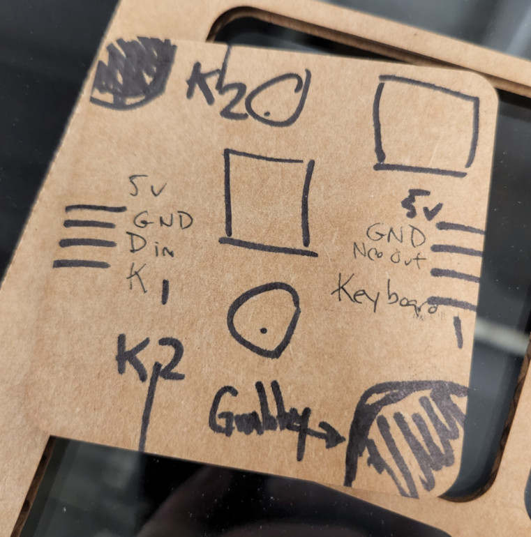
Makes more sense when it’s drawn out.
Now that I had a rough idea of what to do, the task seemed a bit more manageable.