19. Project Development
The Final Stretch
Here it is, the final countdown! cue the music
This is where I’ll go into detail about my last stretch and everything I did to make it happen.
June 2 - Charlotte Latin
It was such a relief to finally hold my project instead of just spinning 3d models around on a screen. It came out great, and it makes me even more excited to complete the larger project on my own time. That doesn’t mean I didn’t have a few hiccups along the way, but all things considered, it went quite smoothly.
I took a half day at work to meet David at Charlotte Latin after noon to use the ShopBot. I didn’t have much time, so once I arrived, I immediately began setting up the files in Aspire. David had the ShopBot ready to go, so after a quick refresher, I ran the first toolpath to mark the locations for the screws.
But of course there was a problem. The plywood that we purchased to do the CNC week project was ¾” thick, but we thought it was ½”. I programmed and designed everything with a half inch in mind, so the first cut was already in the material before it “spot drilled” the hole, then it dragged the tool across the surface to the next location. One quick slap of the E-stop prevented any serious damage, but it meant we had to find material that was the correct size.
David found a leftover piece of ½” plywood that was large enough for my pieces, so we removed the original board and set up the new piece. This time everything ran much smoother.
The next issue was due to an oversight on my part. I had added tabs to my board to keep it in place, but I didn’t check the size of them. They were only ¼” wide and .125” thick, one per side, which is not a lot of holding power on a part 20” long by 8” wide. I noticed how small they were after the profile was cut, but they held for a majority of the remaining cuts. However, three out of four broke while cutting the slot, causing the part to shift. I was watching for any issues, so I was able to quickly stop the program before it completely ruined the part.
David came in and we discussed how to salvage the part. The slot is hidden and is there to hold the wires, so this issue is purely cosmetic. The problem was that it had one more pass to get to the final depth and finish, and I didn’t want to start the entire part over again. David’s solution was brilliant, and full props to him for this idea!
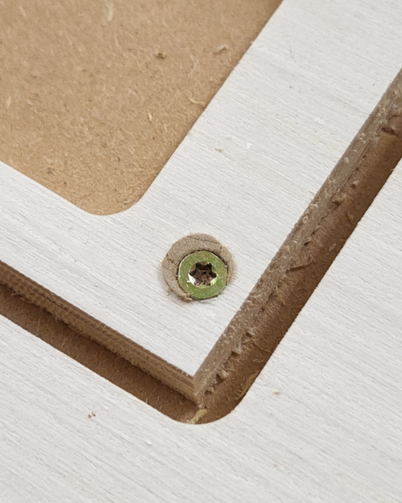
Dowel rods!
I floated the idea of using my through holes for my fasteners to hold the part down and just running the final toolpath, but I was concerned that we wouldn’t be able to find a screw large enough to hold it down. David’s solution was to take a dowel rod slightly smaller than the hole, drill a pilot hole through it, and put a screw through that. The screw would then push the material out of the way, shoving the dowel against the hole and holding it in place. It worked perfectly. Since one tab was still holding, I just had to line up the broken tabs and we screwed the part back down.
All finished and still 100% functional.
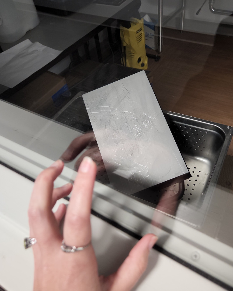
Next on the list was my acrylic. I had a sheet that was too big for the lasers at CPCC, but Latin had Epilog’s largest laser cutter. It works a bit differently than what we have. I had to convert my sketch in Fusion to a dxf, but instead of using Inkscape, they use Corel Draw. I opened the file there, set the line weight to “Hairline” (any other weight will engrave instead of cut) and hit print. In the popup print menu, I aligned my lines with the acrylic. Then I used the plunger option and changed it to vector. But instead of adjusting the settings manually, they have a folder of presets for different materials. I only had to select the correct acrylic setting that matched my material thickness and hit print again. This sent it to the printer, and once confirmed, hit go!
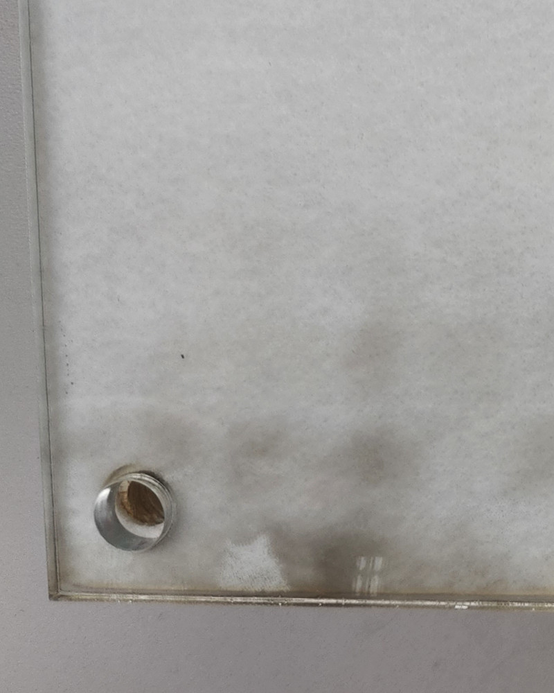
The singed area is the plastic film on the back of the acrylic. The part itself was perfect.
Last, it was back to the ShopBot. I had to jump in line for the laser while it was open; the Latin kids were working on their projects as well.
The original plan was to do a two sided operation. The first run would take care of most of the features, but on the back, I have a step around the large pocket for a piece of acrylic. This is going to be the cover for the power pack and control board. However, David had never done this before, having to line up the same part to machine the back, so in the interest of time, we decided to add the feature later with a router. This time, I made the tabs bigger and put two on the longer sides, and I didn’t have any problems at all.
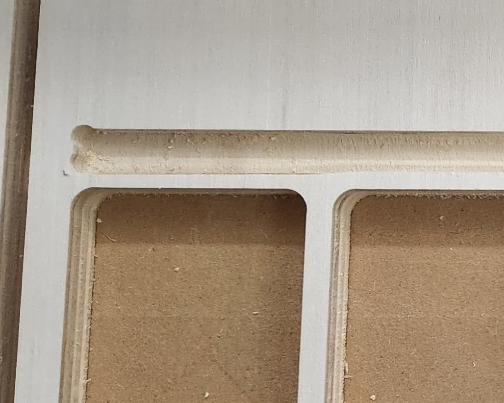
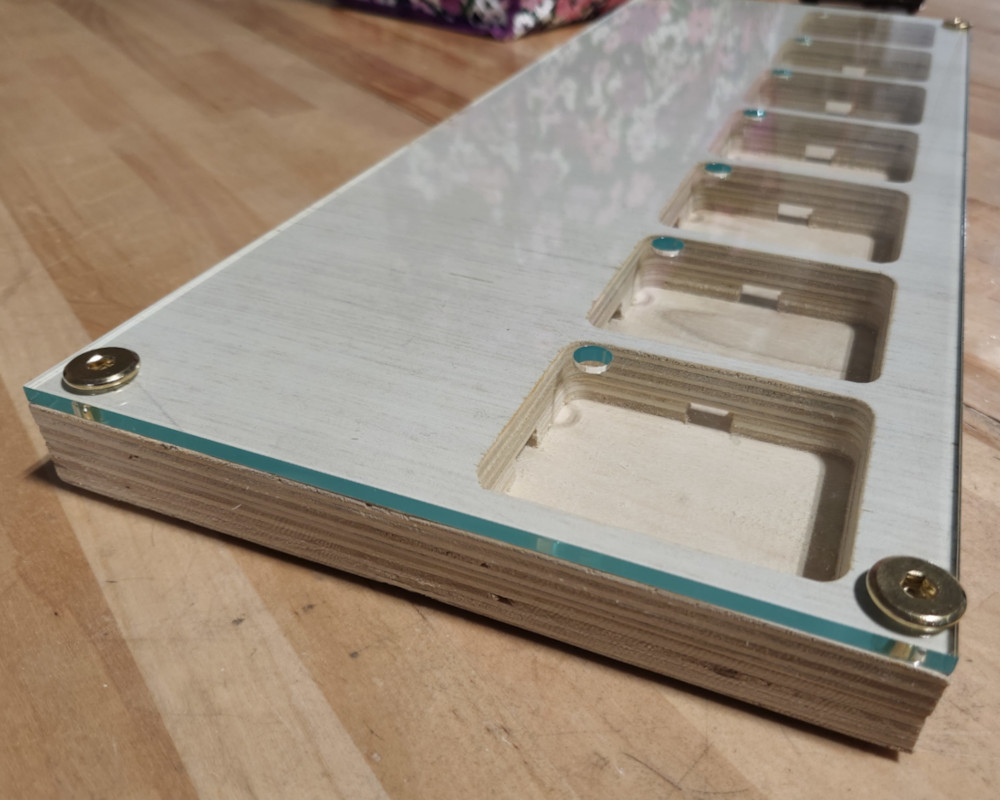
Once all the parts were finished, I did a quick test fit of everything to make sure it all lined up and they did!
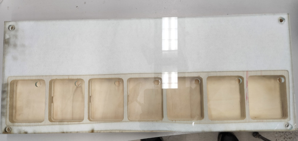
It’s all coming together now.
The holes in the wood are a little tight, but I forgot to oversize them slightly to accommodate the fasteners. I can easily fix that by running a drill through the holes.
Another slight issue is splintering. All the features are on the inside, so sides that will face outwards once assembled were on the bottom when cutting. This meant they splintered around the pockets and holes. The top part will be fine since it’s covered by the felt and acrylic, but the back will need to be cleaned up a bit. I’ll probably paint the wood to make it uniform and to mask the edges of the wood as well. Since this is a cosmetic issue, I’ll do this only if I have time.
June 3 - CPCC Fab Lab
I went into the lab to work on a variety of little things that needed done.
Felt
First thing I had to do was cut my felt pieces. I ran into an issue almost immediately though. Fusion updates quite often, almost every day, so while it’s easy for me to update my computer with the newest version, the school computers rarely get updated. Long story short, I couldn’t open my files at school. Luckily, I had saved some of my sketches at dxf files beforehand, which I could then reopen in Fusion and modify, but I needed the updated hole locations. I was able to call my boyfriend and walk him through saving the updated sketch from his computer at home, so one crisis averted!
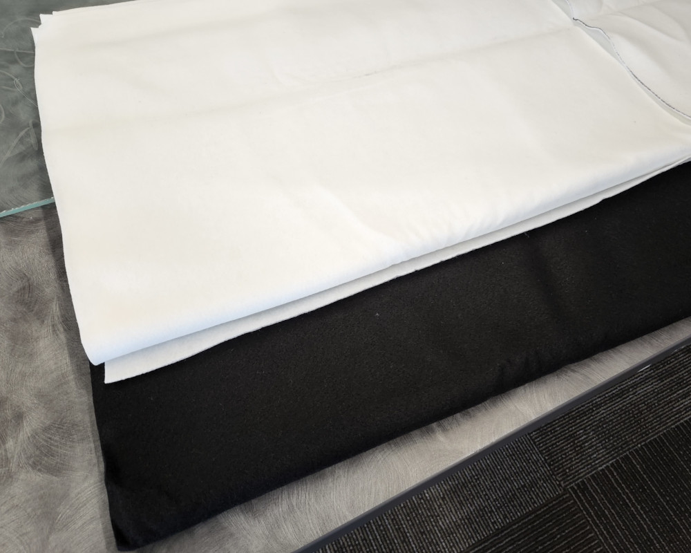
Do you think I got enough?
Once I updated the sketches with the correct dimensions, I cut the pieces out with our laser cutter. I used the same files for the black felt as well, even though I only needed one part of it. It was easier to just run the whole thing again than have a separate file.
I was really happy with how it turned out. This was the first time I had enough material to put them together. The next part will be gluing all the pieces.
Buttons
I needed to finalize my buttons. Since I had the acrylic cut, I used the hole sizes to figure out the diameters of the buttons, then checked how tall they needed to be with a board in place.
I quickly modeled a few different sized pieces and 3D printed them.
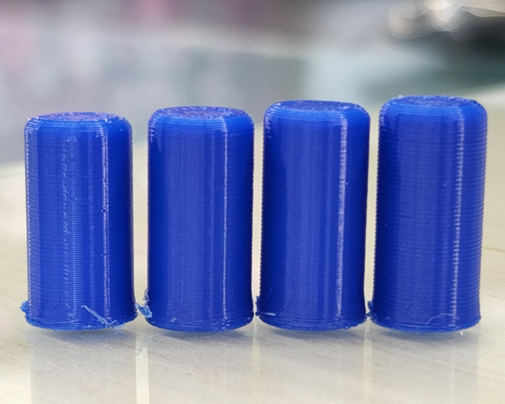
The goal was to get the height and model correct, then print the final parts in clear resin. That didn’t happen.
I cannot explain how frustrating this room has been for me. Always locked. Always. No reason why.
After printing on the FDM printer, I checked each one and found the one that wasn’t too high above the acrylic and felt the best when pressing.
Sanding and Fine Adjustments
I mentioned how I had messed up when I made the through holes for my fasteners. I used the exact dimension of the hardware instead of adding wiggle room, but it was easy enough to fix.
I went downstairs to the machine shop and grabbed a couple drills that were the next size up, a hand drill, and some sandpaper.
I didn’t want to open the holes up too much. I wanted it to be a relatively snug fit, or at least enough that the pieces wouldn’t wiggle around. So I started with the “S” drill, or 0.348”, and did a test fit. It was still difficult to get the fasteners in, so I switched to an 11/32, or .3594”. After a quick run through the holes, the hardware fit perfectly.
The next issue was the hardware itself. I bought the pack from Home Depot, and while the quality wasn’t great (you get what you pay for), I at least expected it to screw together. Unfortunately, one of the screws had burrs on the threads, so I used a die and cleaned them up. All the other pieces were fine, so it was easy to assemble everything.
It’s all starting to come together now.
June 7th - CPCC Fab Lab
I had a few things to check off the list. First, I needed to do some housekeeping with my site. Second, I had to print the buttons. And last, I had to finish the design of the control board, mill, and solder it.
The first part was simple enough. I got my questions answered and some details squared away.
Then came the fun part.
Buttons
I decided to print my two shortest button models, one set of each, just in case one is too tall when I install the breakout boards. I also quickly designed a polygon cat head to put on the button for Saturday.
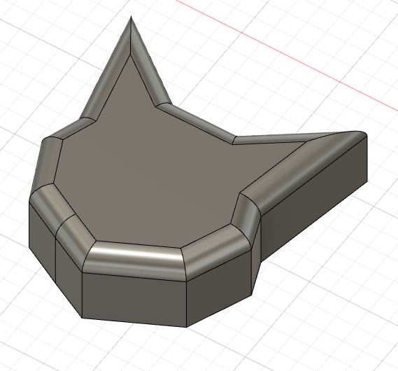
Cat head for Caturday.
After my issues with the post processing room last week, I left a note requesting the room remain unlocked, and it worked! I was able to get the print bed out and set up the printer. Once set, I sent the file and it started up automatically.
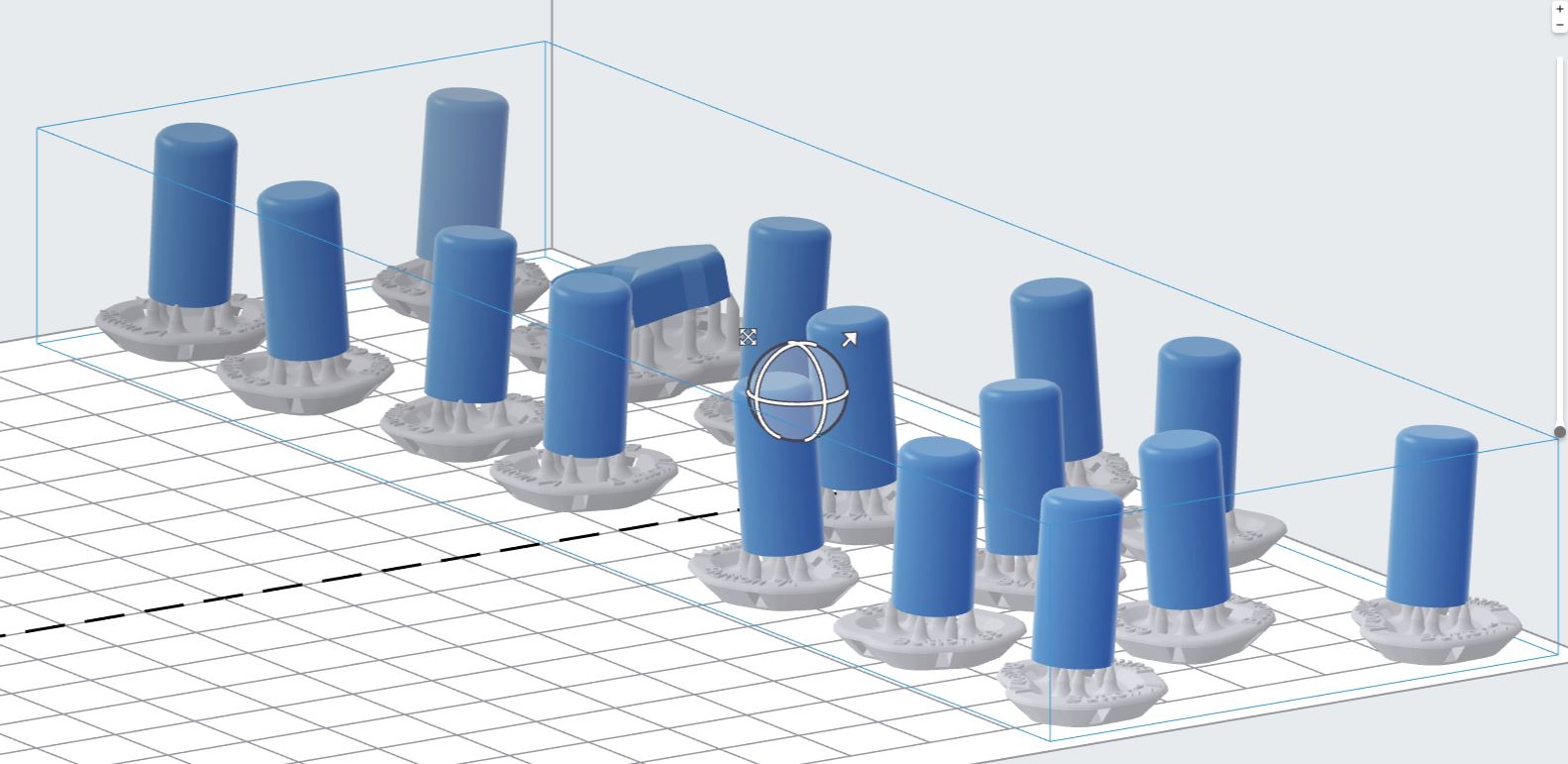
The print took roughly an hour and 45 minutes to finish, and I was shocked at how good they looked on the bed.
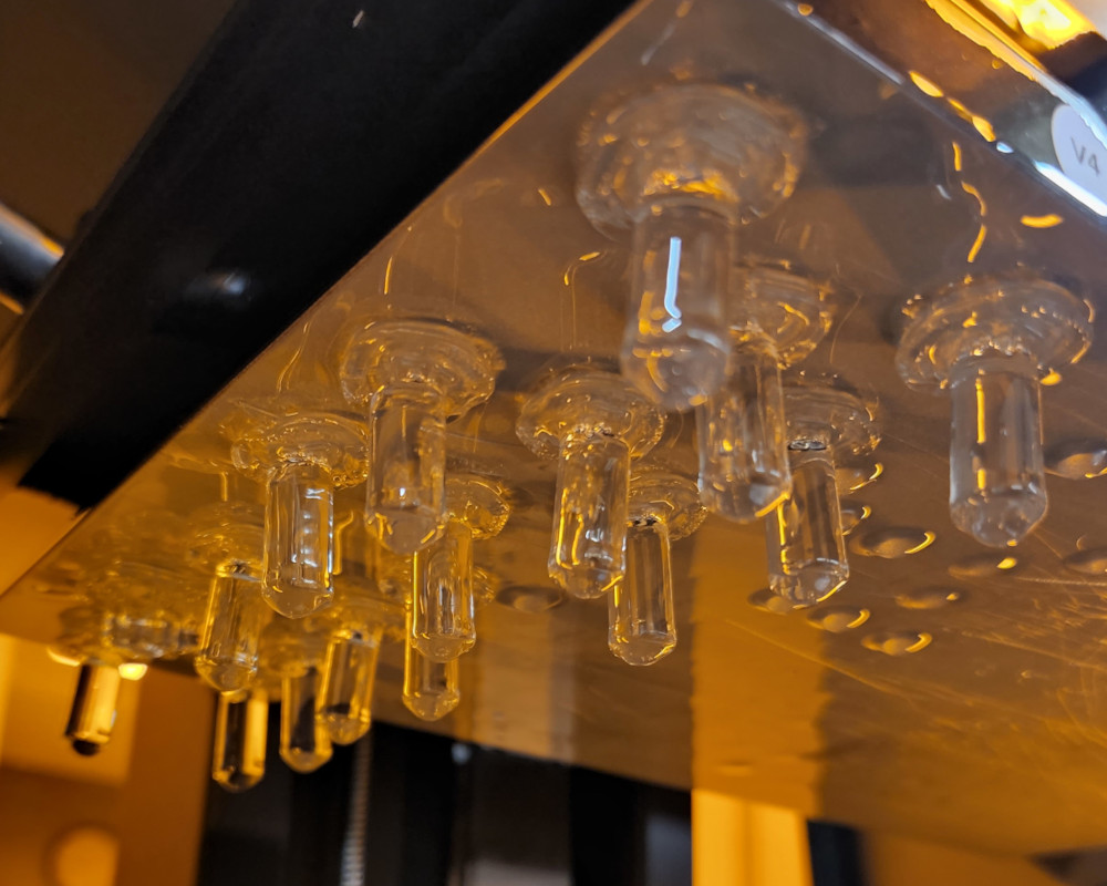
They’re almost perfectly clear!
I was expecting to see some layer lines, but what I figured out is that the excess resin was filling in those lines. I wiped the extra off the cat head, which revealed all the lines. I didn’t want the layers to show, so I dipped it back in the vat of resin in the printer to create a smooth layer on top.
Then, with Garrett’s help, I moved all the buttons to the curing station. We decided to try curing the buttons with the excess resin in order to preserve how clear they were.
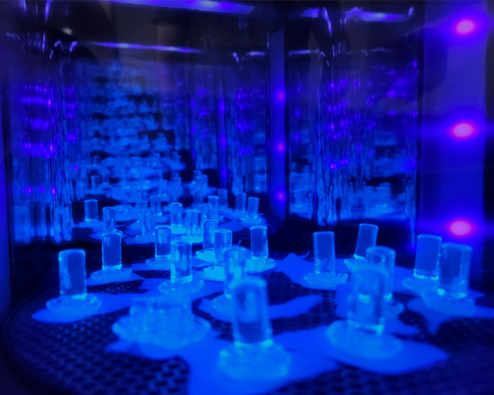
I love the colors and the infinity mirror effect. It looks amazing!
We started with the recommended settings, but the resin was still sticky when we checked, so we set the timer for another hour and left them.
I’ll have to check on their progress when I’m back in the lab later this week.
RMA Control Board
Let me just start by saying how proud I am of this board. I had most of the schematic done, but I wasn’t sure about a few details, so once again, Garrett was a huge help.
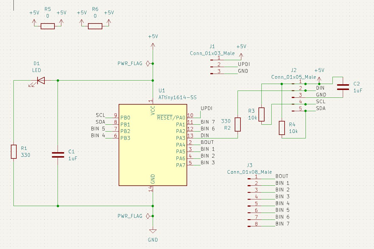
The trace game was also easier to manage this time. I won’t say it was easier, because there was still a lot of rearranging and pin switching, but overall, way better this time.
Plus I was able to make it way more aesthetically pleasing.
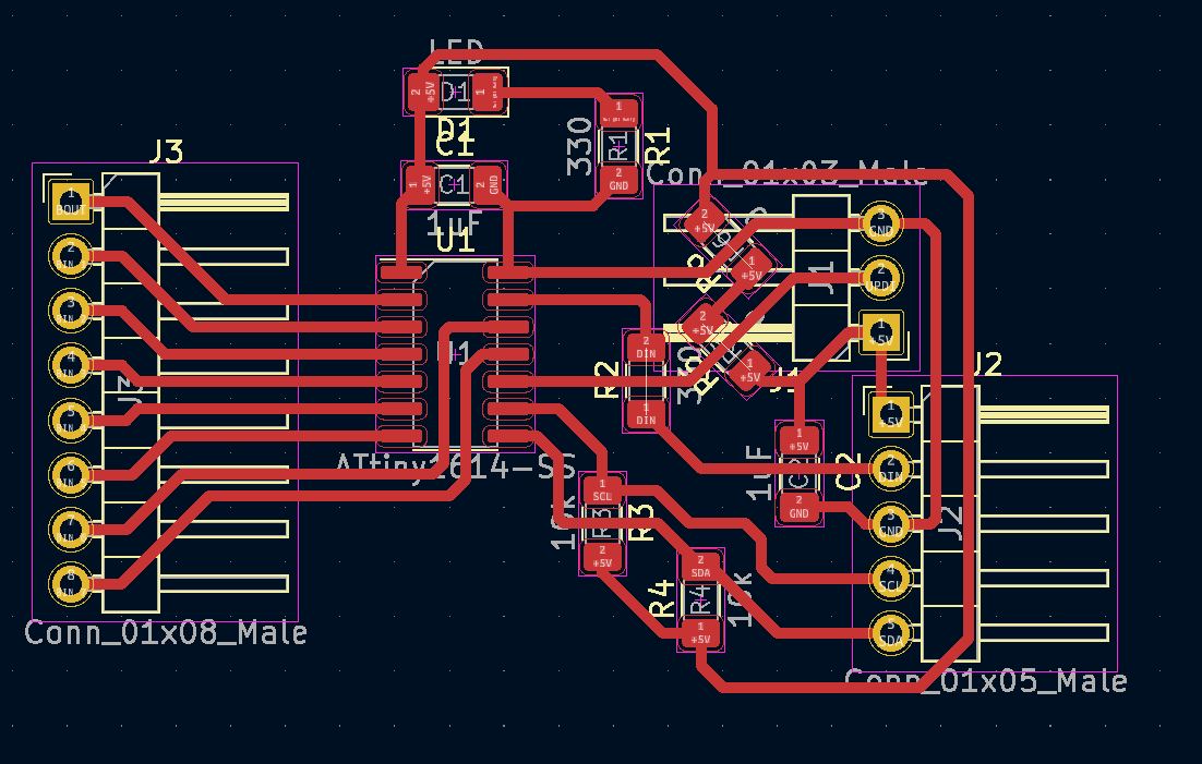
It looks halfway professional with the labels and everything!
Then it was rinse and repeat to mill and solder everything together. By this point, it was super late, so I didn’t have time to test out the board. That’s a job for tomorrow.
June 9 - Work from Home
There’s still plenty I can do at home between trips to the lab, so here we go.
Felt
This pesky felt. Moving forward, I’ll probably avoid using felt and glue in the same project, at least in this respect. A lot of the posts I found with Google assumed the felt was cut with scissors or a die cutter, so they didn’t have to account for the melted edge.
My main issue was that the felt I’m using only worked with certain super glue. I tried the Gorilla Glue, but it oozed a lot and was really messy. It left puddles on the back side that dried into hard spots on the surface. I switched to Krazy Glue, and it worked much better.
I was still running into issues if I didn’t use enough glue. Some of the melted sections were cracked, so the glue would wick into the regular felt before I could glue it together.
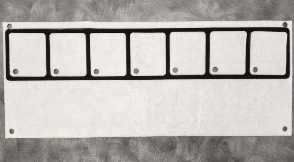
But I finally got the right ratio of glue to felt and got all the pieces together.
The other issue was shrinkage. The white felt inserts were slightly smaller than the squares itself, most likely due to how the laser cutting melts the material, so the spacing was slightly off. I had to stretch the felt to line up the holes, which was both a good and bad thing. Bad because it was a bit of a hassle to line up the holes. Good because the material was kept tight with the fasteners.
June 10 - CPCC Fab Lab
The days are getting longer and the amount of time till the deadline is getting shorter. Yet the list of things to do never seems to shrink.
Housekeeping
I had a lot of folders to clean up and a lot of files to organize. The files in particular had gotten out of had, just with how many iterations and prototypes I had worked with.
Through this whole process, I’ve been using Google Drive to keep all my things organized, pictures, notes, and my write ups. That way I could work on them from work while waiting for a part to finish. It helped a lot throughout this process, and I’m much more organized now than I was when I started.
That doesn’t mean the final project portion hasn’t gotten a bit messy. I took some time to get everything straightened up, and now can easily find my folders and files.
Just a little quality of life thing behind the scenes.
Breakout Boards
Now I had to redesign the breakout boards. I know the boards I had before worked, but the button wasn’t positioned correctly, so I couldn’t press it through the holes. I had to figure out a way to design the board with measurements, something I wasn’t sure was possible with KiCad.
First, I recreated the board in KiCad. I removed one set of headers from the bottom of the board, as there wasn’t going to be anything connecting there. Once I double checked that I had all the components, I opened up the trace game.
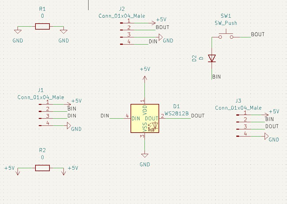
I switched to a different layer and started playing around with the different drawing settings. After trying each option, I found an inspect option. It worked fairly well, but it is not fixed to a specific point; I can move the end points in any direction to change the displayed number. Fortunately, I didn’t have to be exact with the location. I just needed to get it close enough.
What I ended up doing was creating the outline of the pocket, getting close to the actual size, one or two thou, then I marked the location of the button with two more lines, again dimensioned as close as possible. I used the intersection of the lines as the center point of the button. Then I marked the halfway point on the top and sides for the connecting channels. The wires will connect through these channels and plug directly into the board beside it.
Once the “pocket” was finished, I moved the pieces into their positions and made the connections. This trace game wasn’t too bad this time. I fixed the, not necessarily problem, but potential issue where the headers from one board were flipped on the next, forcing you to twist the cable. This time, I made them a direct connection, the same on both ends. I then created the outline of the board. It wasn’t as aesthetically pleasing as the control board, but it does the job.
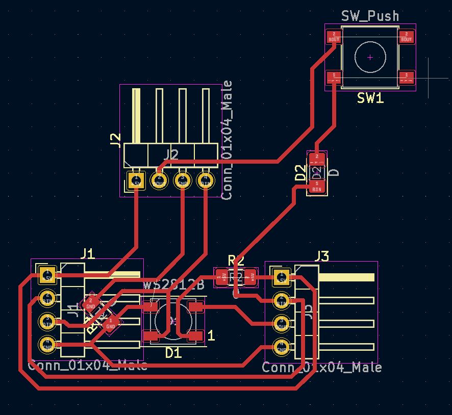
From there, it was simply a matter of prepping the files and milling them out.
Testing
The next thing to do was to test the boards. I started with the first one and used the control board and programmer to run one of my proven programs. The first one worked! The second one, yes, but it required a bit of tweaking of the code to get both NeoPixels to light at the same time. The problems started when we connected the third board. For some reason, the NeoPixel wouldn’t light on the third board, but the buttons would work on all three. But then the button on board three was controlling board two.
Since Garrett is the better programmer, he started trying out different options while I continued milling and soldering the boards. This way I could get the boards done, they could focus entirely on the programming. This took us most of the evening, and by the time we finished, it was close to 11 PM.
June 11th - Home
It was time to call in the big guns.
Programming
My main issue is that I had three programs that all did different things, and all worked, but I needed to put them together and make them all play nice in order to do exactly what I needed. The proved to be more difficult than initially anticipated.
I had asked my friend Jenny for help earlier in this project for some programming help when the time came, and I called that in today. She came over and we spent five or six hours trying to get the code to work. However, a large, very large, portion of that time was spent troubleshooting technology in general.
We started on my laptop, but it wouldn’t read the programmer. We tried an Arduino, just to check if it could read anything, but we got a different error. This time, it said the port was corrupted. We tried all my USB ports, but none of them could read the Arduino. We switched to my desktop, and it read it just fine.
So. We abandoned the laptop and set everything up on the desktop.
Then it was just a series of trial and error. In the end, we called Garrett and spend a couple hours consulting and rewriting code over the phone. We got pretty close, but weren’t able to get a working code.
June 13th - CPCC Fab Lab
If this section is for crunch time, then the last two days are for fully compact, black hole levels of crunching.
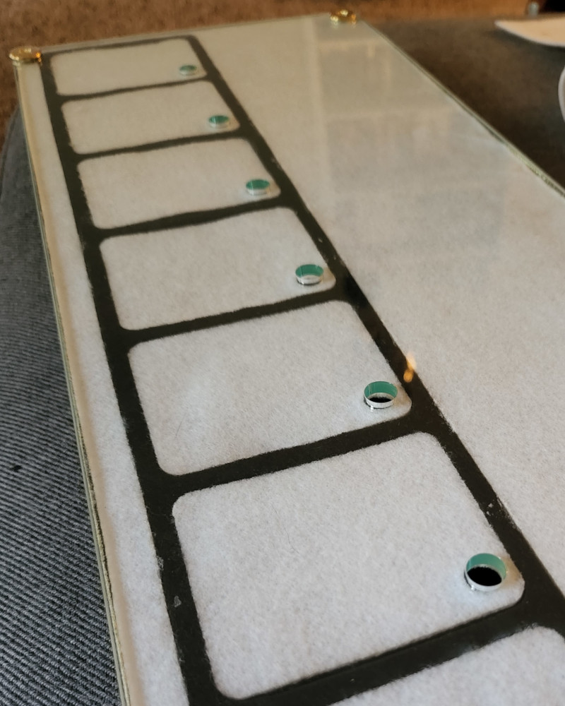
Main thing that needs to happen: the program. But there is one more thing that I want to do for my project. I want to use the vinyl cutter to label the days. I think it will look really cool against the frosted glass effect.
Labels
Since it doesn’t take long to set up, I used Inkscape to quickly created a file for the vinyl cutter to cut out the days of the week, as well as a label for “Notes” and “Week Of”.
One thing I had to consider was to mirror the stickers so they are the correct orientation when stuck to the underside of the acrylic. After I decided on the size and font, I was able to print directly from the computer. The main issue I ran into was caused by the font.
In Inkscape, calligraphy and script font looks like it’s connected, just like in regular handwriting, but when the filler is removed, the outline of each letter is shown, and they are not removed where they overlap. This translates to the vinyl cutter, meaning it makes a cut for every single line, even if it’s not necessary. It became an issue when the pieces became really small and hard to keep together when removing the extra vinyl. It was also an issue where there were close corners. The cutter did not go completely into the corner, leaving material that had to be cut in order to weed it properly.
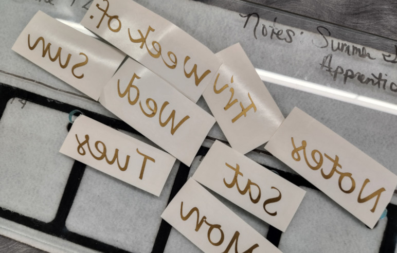
Overall, a pain in the ass. But the end result looked amazing!
I used the felt as a guide to line up the words, both in spacing and to keep them relatively straight.
Programming
With the labels done, Garrett came in to help me with the final code.