For this assignment I decide to make and design a bracket for my TV decoder modem to hang on my wall near to my desk studio. The design of this support I inspired in a TIE Fighter from Star Wars since I wanted to give my work a touch of my personality. I designed on
Rhinoceros. Below I show you my steps.
Holder for my TV Decoder modem
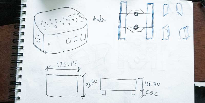
STEP 1. Drawing and take measurements.
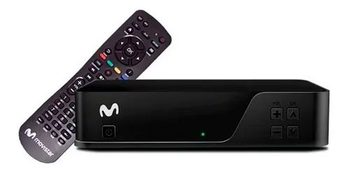
Picture 56. This is the original object, it is very small but it takes up space which I do not have on my desk, so I thought about making this support to be able to stick it to the wall.
 Picture 56.1.
 So, I decided to design a support for this object to have a greater order and also visually appealing .
 Picture 56.2.
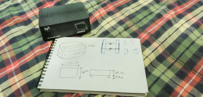 STEP 2.
 Thinking to my design
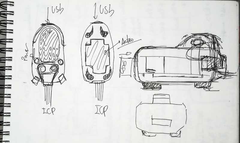
For my design, I think I make a bracket to hang on my wall and I want a touch of personality, so I adapted the shape of my bracket design to a TIE fighter.
Picture 57.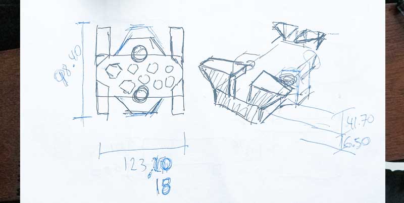 STEP 3.
 Drawing in Rhino
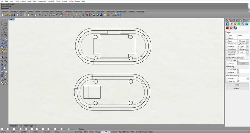
Trace my drawing on Rhinoceros, just like my design.
Picture 58.
That has a reason. Because my modem has holes for ventilation andin the bottom have rubber dowels, that's why it's a TIE fighter.
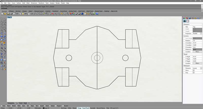 Picture 58.1.
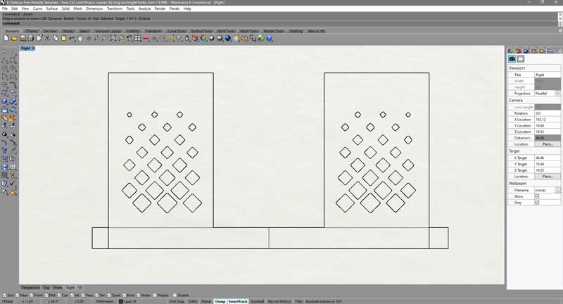 Picture 58.2.
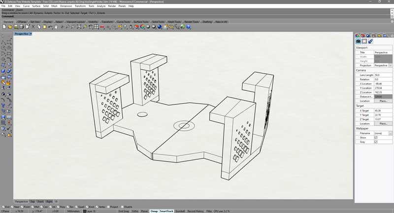 STEP 4.
 FInal details
After finishing my modeling on rhino, I showed my teacher and he gave me a suggestion, that some edges especially those with a 90 degree angle that give them a fillet so that it has a better grip and resistance when printing. And I divided it in half so that it has more precision when placing it on my wall.
Picture 59.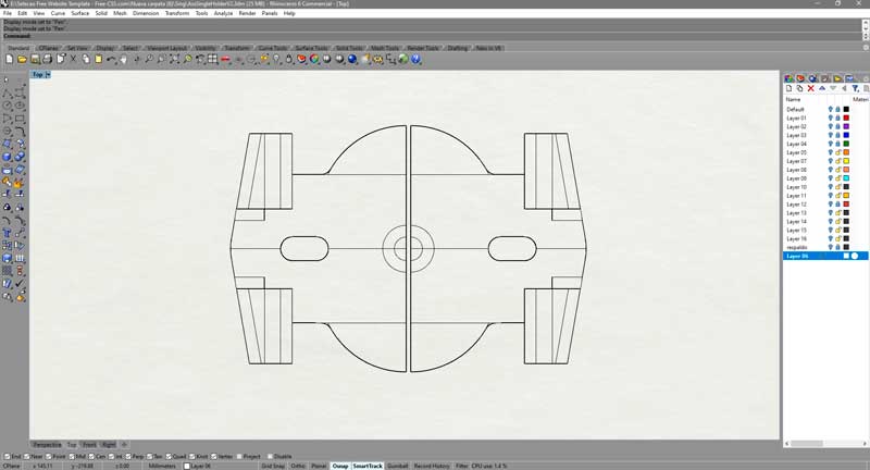 Picture 59.1.
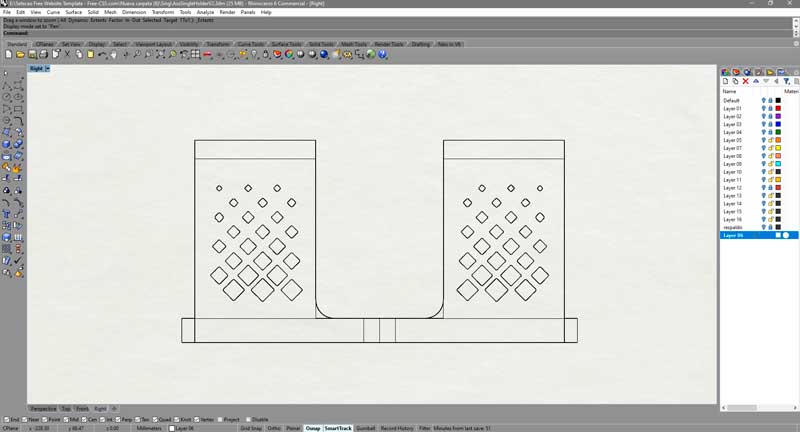 Picture 59.2.
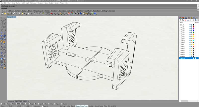 STEP 4.1.
3D view
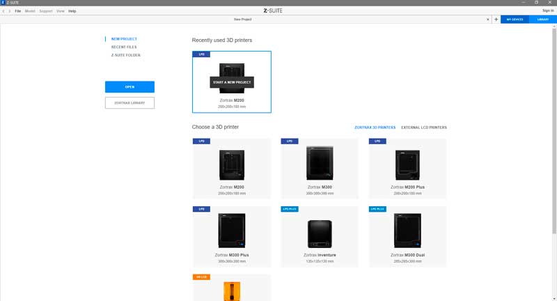
STEP 5. Upload to Z-Suit software by Zortrax
Picture 60.
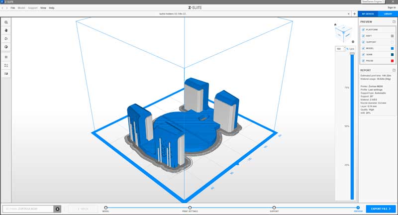
I upload the stl file to the zsuit, for that first I open the program then I select the printer model in my case it is an m200 and I click on it.
 Picture 60.1.
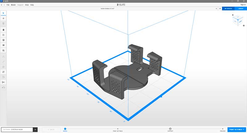
Next I clic on the blue botton that says print settings, in the right corner below.
 Picture 60.2.
Finally I configurate my model to print, first I select the material in my case I use ABS fill, next I put 20-grade to suport, next I put 0.14 for the nozzle diameter for a better quality finally I writte the infill I prefer used 20%, because more fast to print.
 STEP 6.
Printed
Picture 61.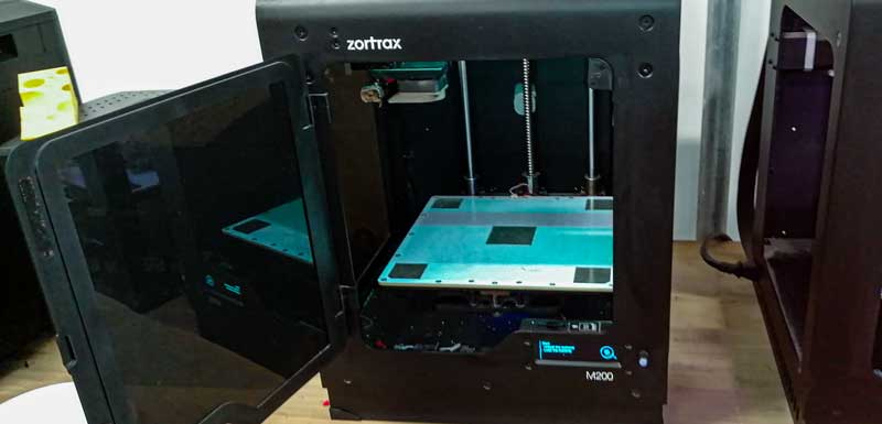 Picture 61.1.
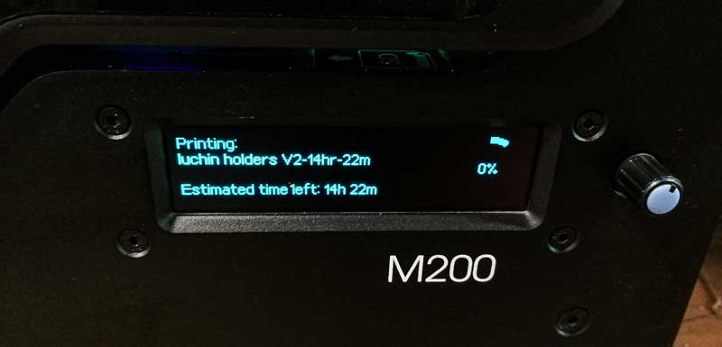 Picture 61.2.
 Picture 61.3.
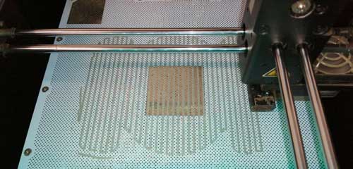 STEP 7.
Before the Print
After the print, I retired the 3D model printed from the 3d printer.
Picture 62.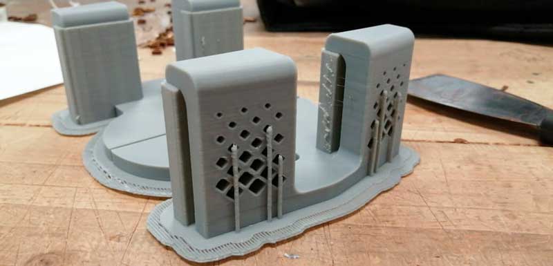 Picture 62.1.
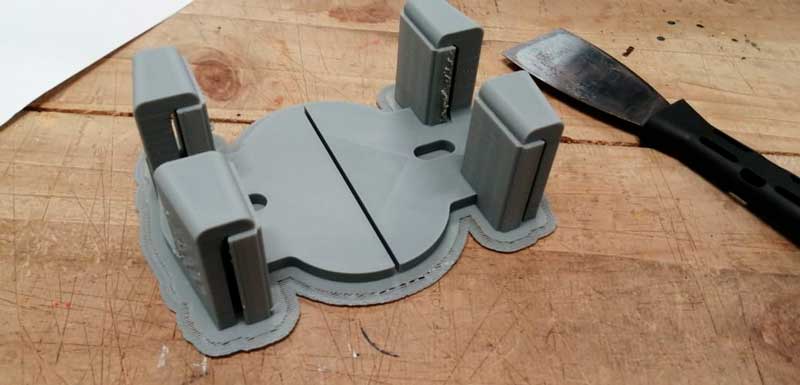 STEP 8.
Final view
Picture 63.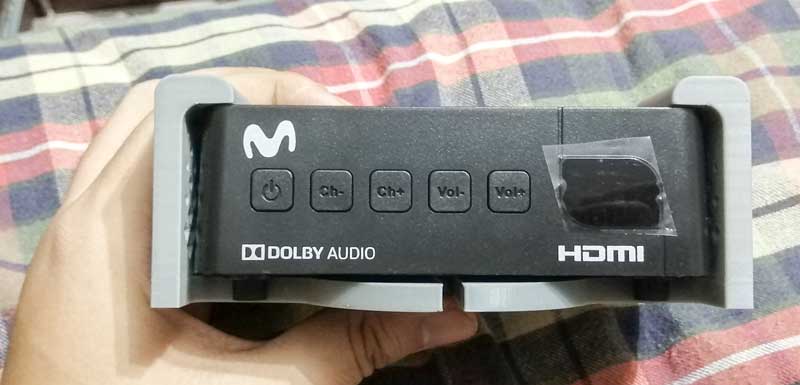 Picture 63.1.
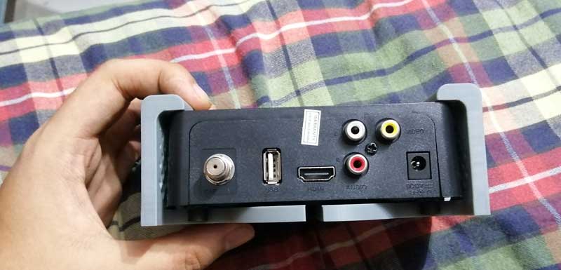 Picture 63.2.
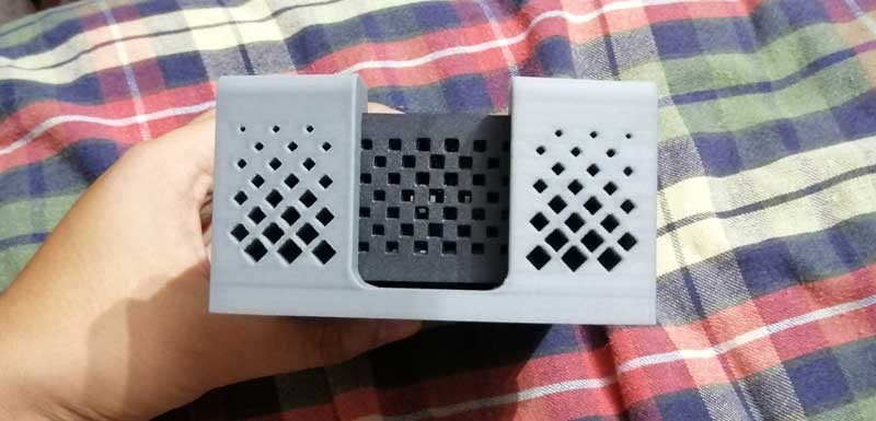 Picture 63.3.
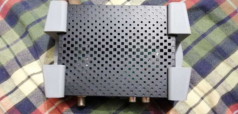 Picture 63.4.
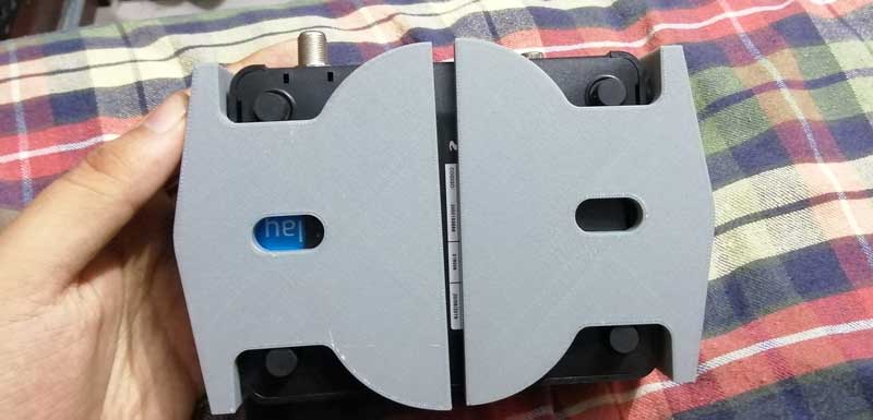 Picture 63.4.
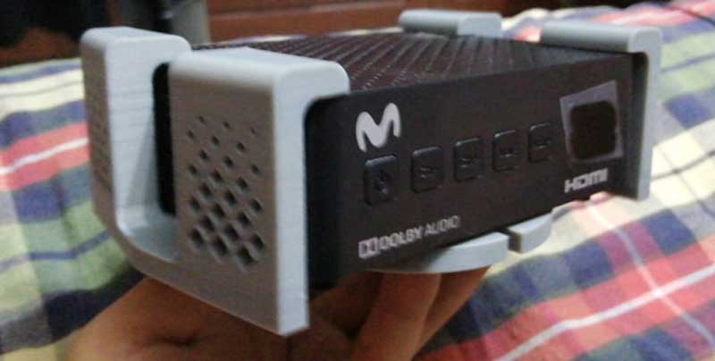
Case for my PCB-in-Circuit.
STEP 1. For this object, I designed and drew a shield for the programmer pcb, like a Star Wars communicator.
Picture 64.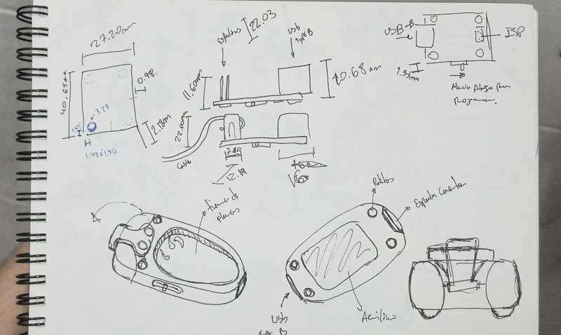 Picture 64.1.
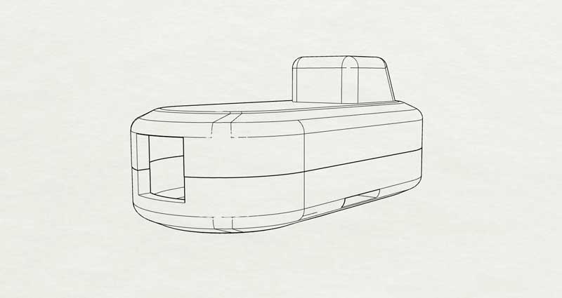
But I realized that the shape I was doing has the appearance of a mini submarine so I decided to continue with the design of the mini submarine.
 STEP 2.
 3D modeling
Picture 64.2.So, here I show you my final design of my PCB Case, I modeled in Rhinoceros.
 Picture 64.3.
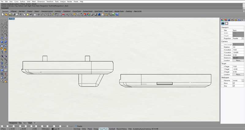 Picture 64.4.
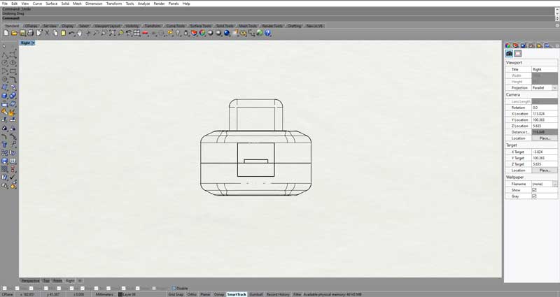 Picture 64.5.
You can se better my Submarine Case 3D model.
 Picture 64.6.
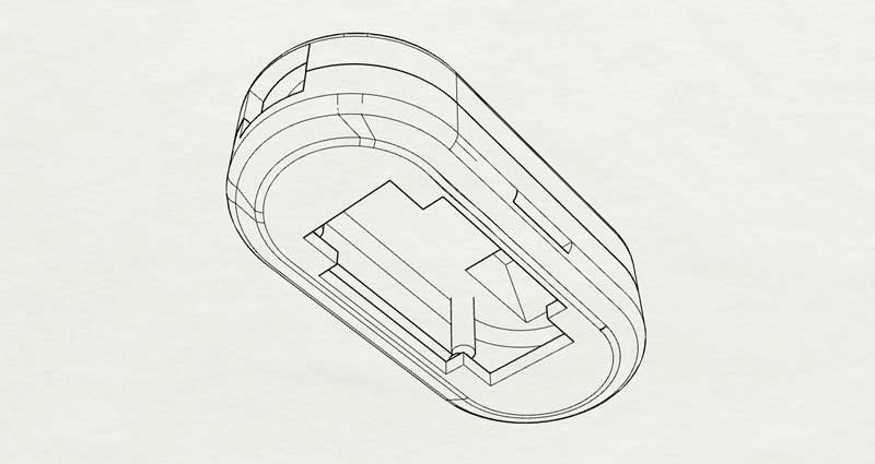 3D view.
STEP 3.
3D view.
STEP 3. Print
Picture 65.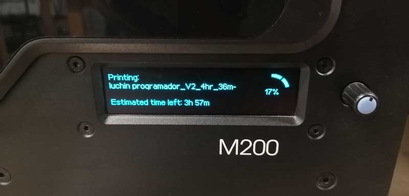 Picture 65.1.
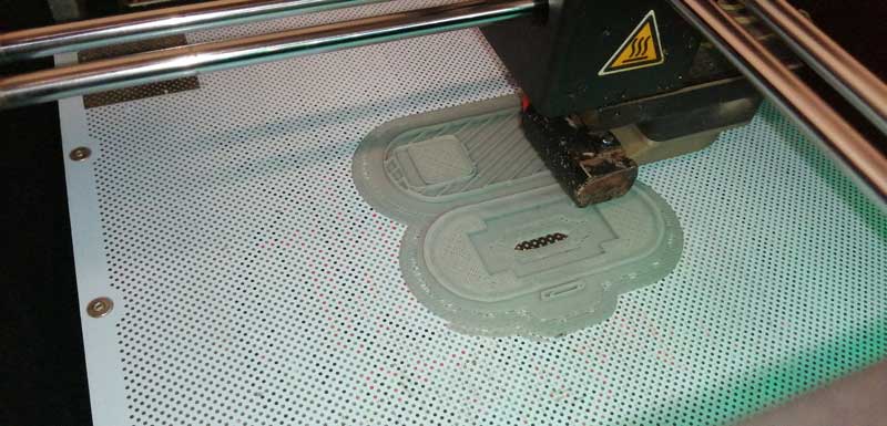 Picture 65.1.
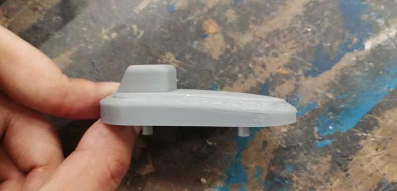 STEP 4.
 Ensambled
Picture 66.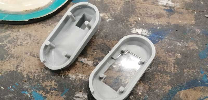 Picture 66.1.
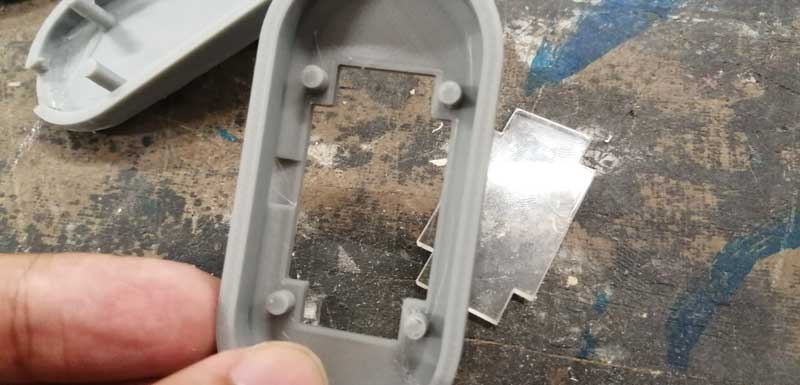 Picture 66.2.
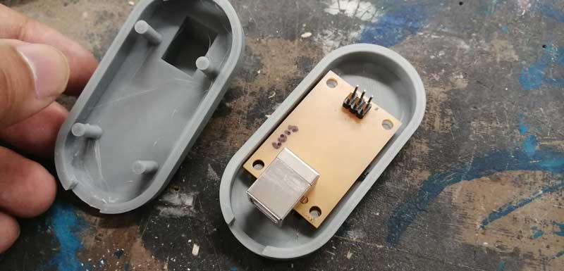 Picture 66.3.
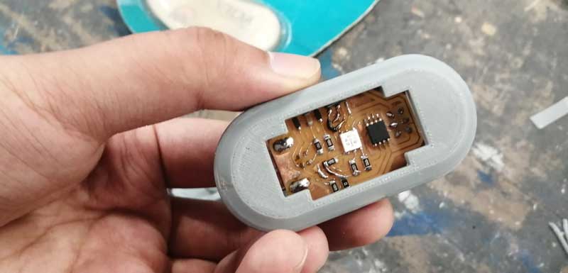 Picture 66.4.
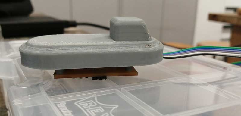 Picture 66.5.
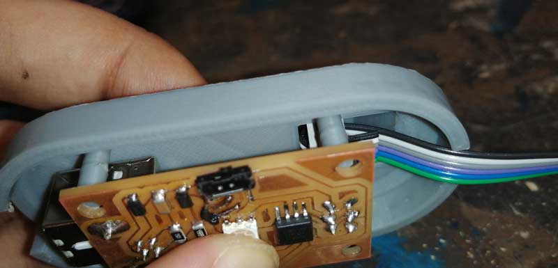 Picture 66.6.
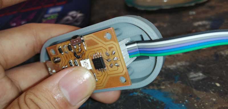 Picture 66.7.
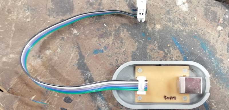 Picture 66.8.
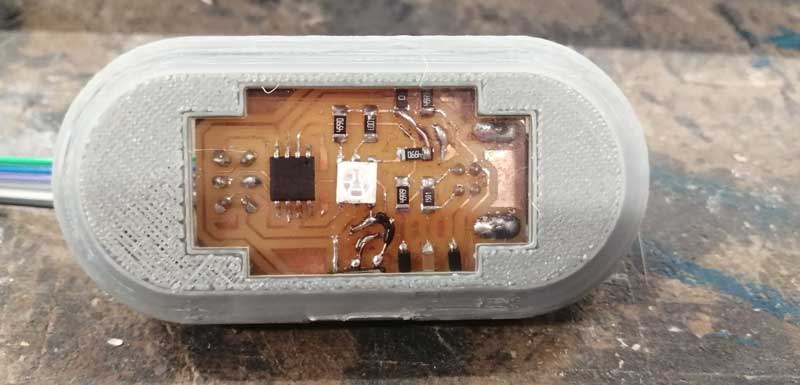
Holder for my HDMI Hub.
This is and extra 3D model I design and printed in this week, This model is a Holder for HUB HDMI goes on the wall it is glued with double-sided tape, I design this because this HUB hinder my work espace thats why I think to this 3D model. I have other 3D models in Sckechfab.
STEP 1. Design and Draw
Picture Ex.1.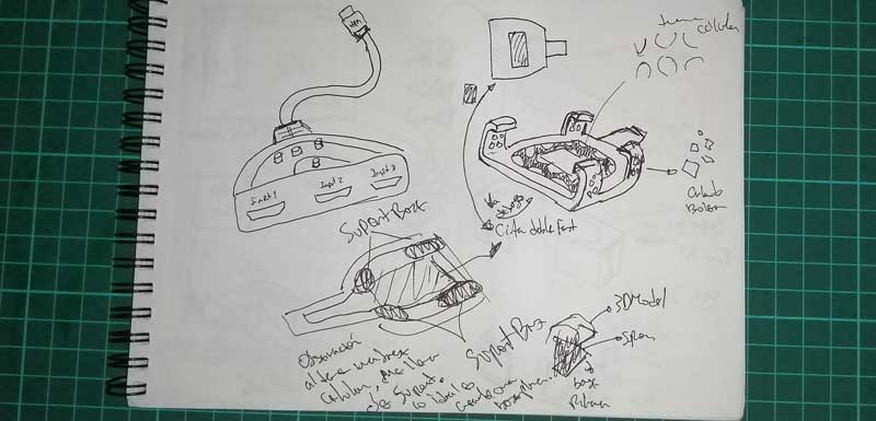 STEP 2.
 3D model
STEP 0. Printed
Picture Ex.2.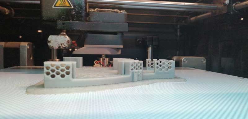 Picture Ex.3.
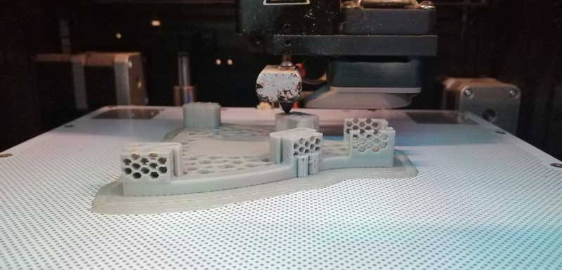 Picture Ex.4.
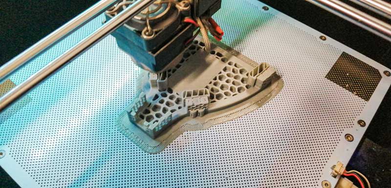
For this part I decided have something fun, that's why I scanned one of my favorite pokemon
Bulbasaur to make this I used the
Shining 3D EinScan-SE 3D Scanner for do mi assigment. So I experiment used in my 3d scan project. Below are the steps.
Picture Maching.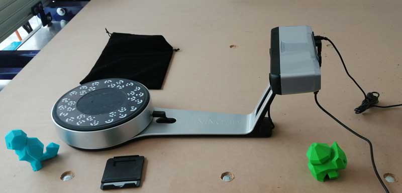 Picture Maching 1.
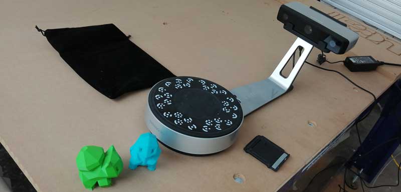 STEP 1.
Caliber the 3D scan machine
Picture 67.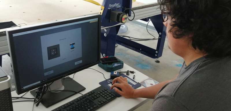 Picture 67.1.
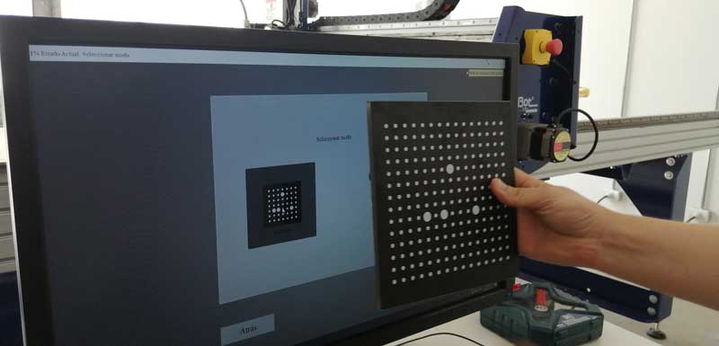 Picture 67.2.
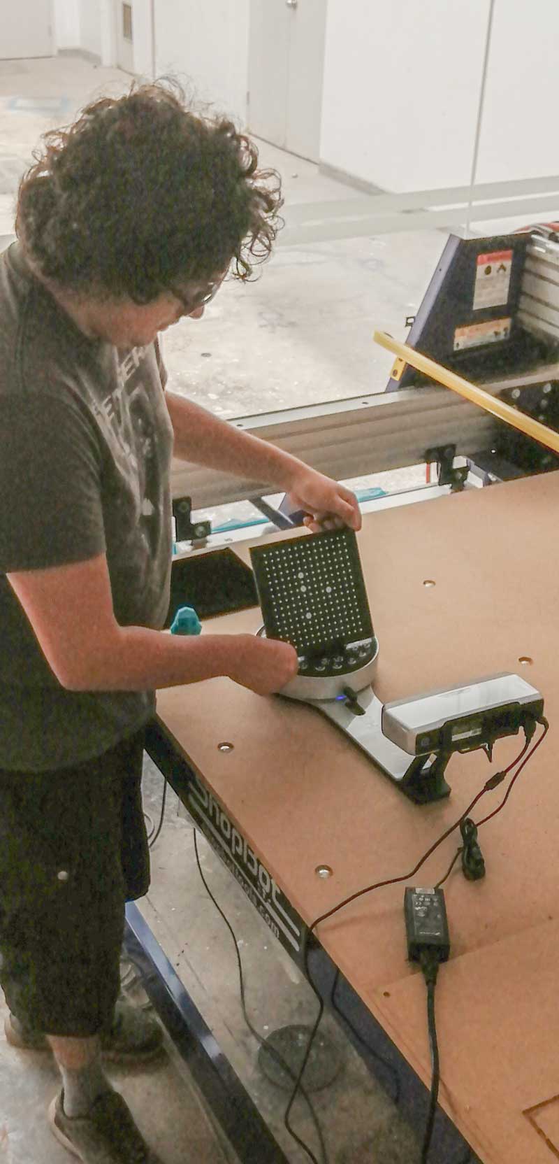 Picture 67.3.
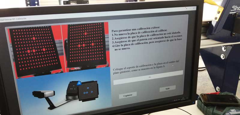 Picture 67.4.
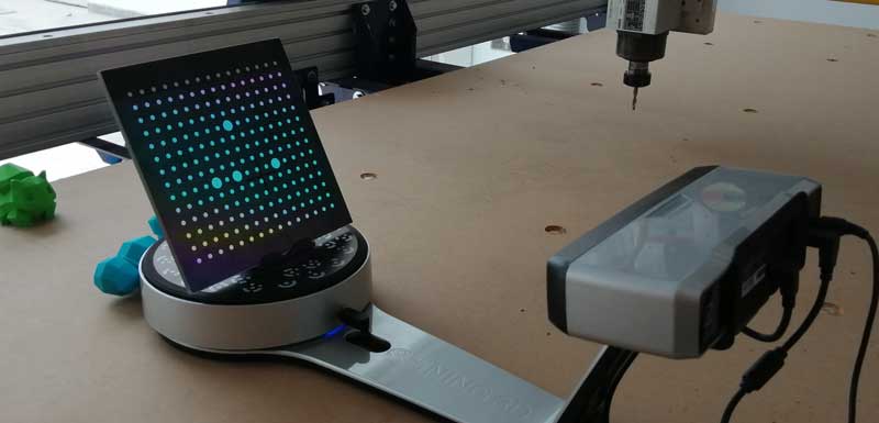 Picture 67.5.
 STEP 2.
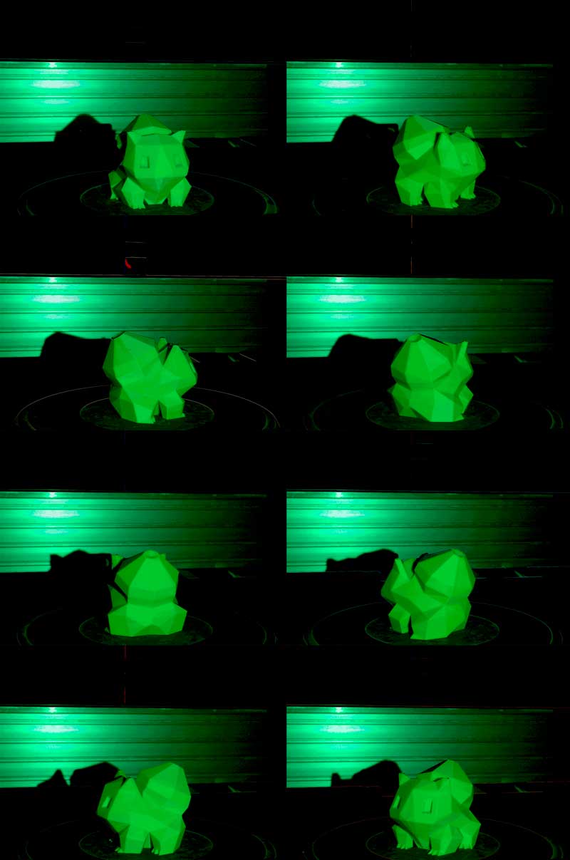
Put my object and Scanning. After the calibration we start scanning my pokemon.
Bulbasaur I choose you!
Video01.
Picture 68.The scanning process is to send a few rays of light and by means of image captures that it collects while the object rotates 360 degrees it collects information and then generates a 3d copy of the original object. Below I show you some images of this scanning process
 Picture 68.1.
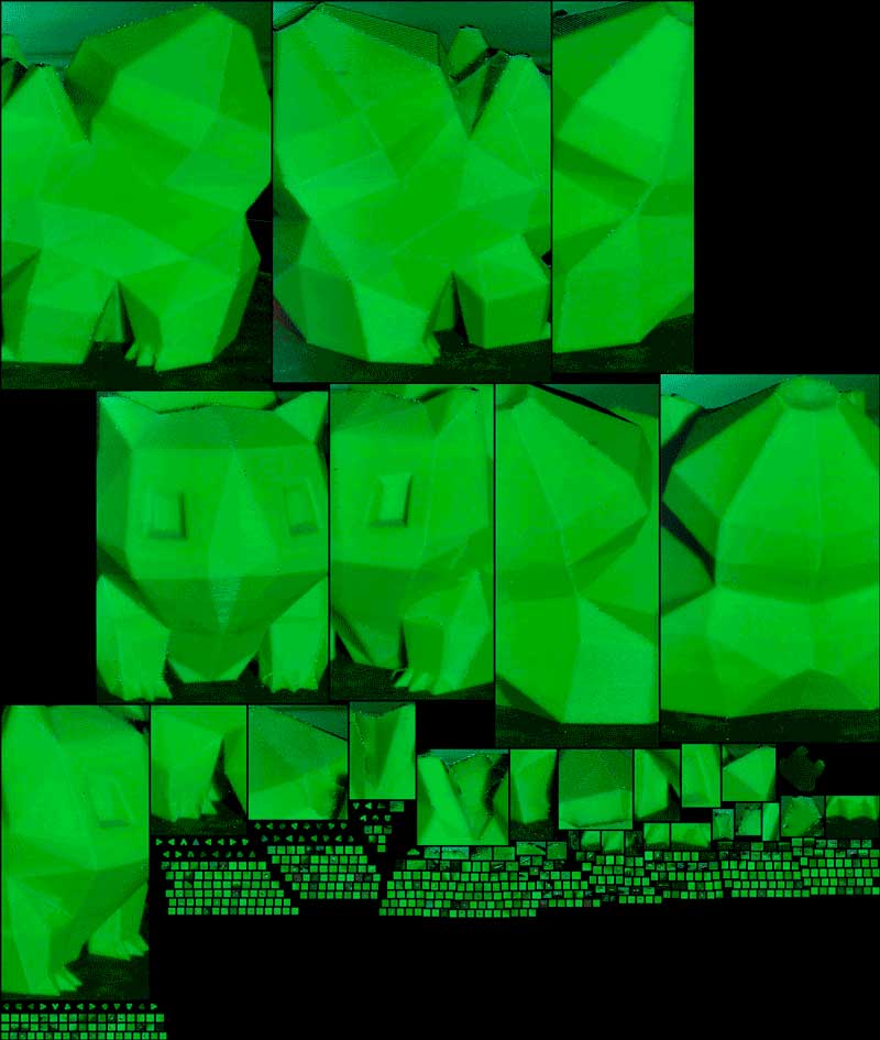
Then, to take the information, the software will calculate and display a preview (videoscan01) if it is ok, click on next and the program completes you, better said, fill in the spaces that cannot scan and have gaps (videoscan02). Finally, if you settle for the result, you have this final view (videoscan03) and save the scanned file in the stl extension for you to print directly.
Video02.
Video03.
Video04.
STEP 3.
Take the
Scan File and printed
Files. BulbasaurScan
STEP 4.
Inport to the Z-Suit software and prepared to print
Picture 69.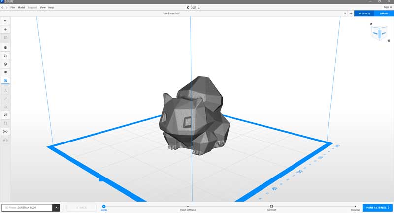 Picture 69.1.
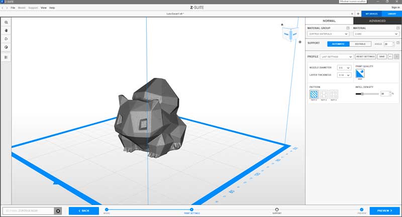 Picture 69.2.
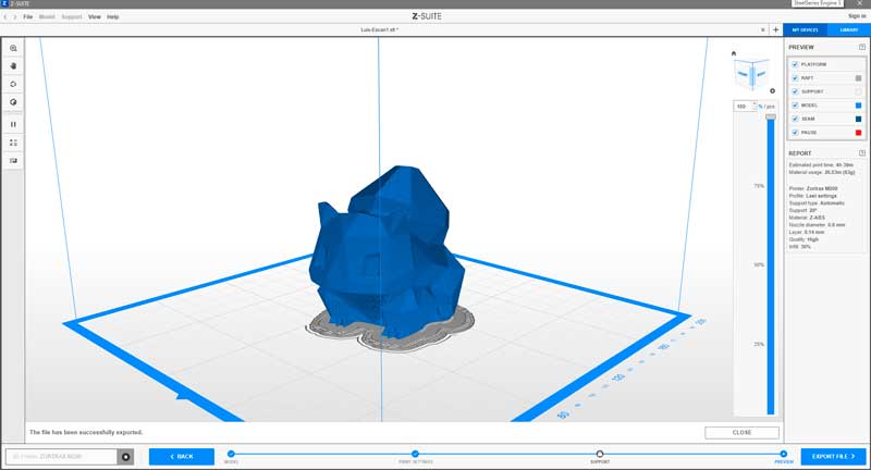 STEP 5.
 Before the print
For optimaze time my partner and me decide printed togeder us 3d scan print, this is the result it seems a real good image quiet identical at the original.
Here the pokemon printed in a Zortrax 3D Printer
Picture 70.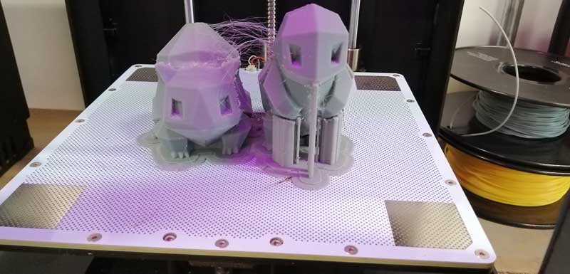 Picture 70.1.
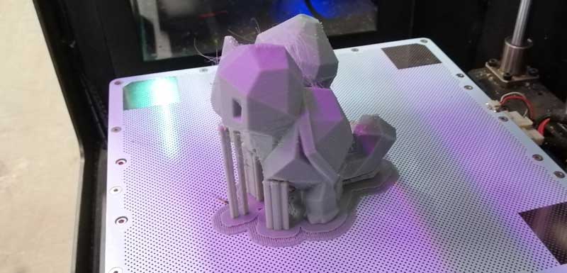 Picture 70.2.
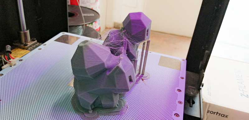 Picture 70.3.
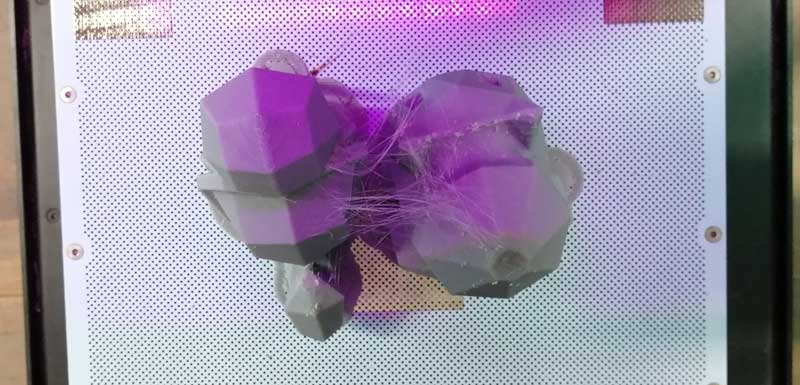 STEP 6.
 Final view and comparation both, Real vs Copy.
The quality its very good, but at the intersections of the joints, the scan filled those spaces since the light rays that I used at the time of the scan could not enter these holes.
Picture 71.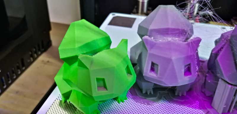 Picture 71.1.
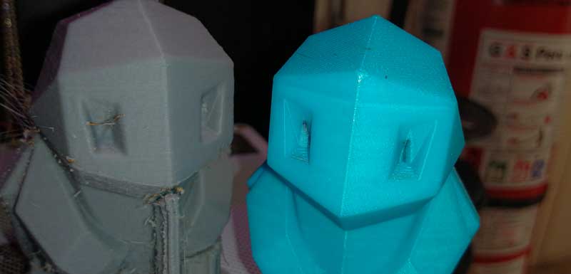 Picture 71.2.
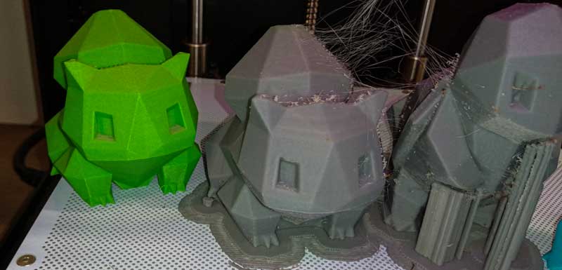 Picture 71.3.
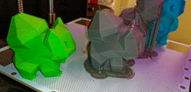 Picture 71.4.
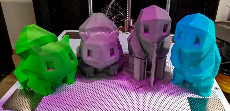
========== 3D Testing ==========
We work with my partner Manuel and use the
M200 by Zortrax 3D printer for made this assigment we use abs filament., we
document the process as shown below step by step.
STEP 1. Select the test design
we used
"Finish - Overhang - Thickness - Clearence"
Picture Test-Finish.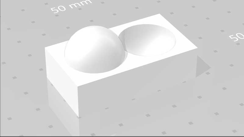
-
download stl file
Picture Test-Overhang.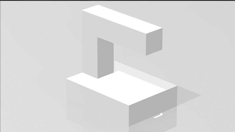
-
download stl file
Picture Test-Thickness.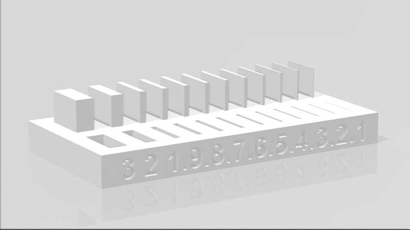
-
download stl file
Picture Test-Clearence.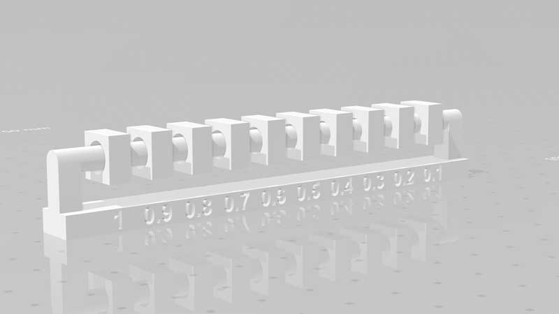
-
download stl file
STEP 2. Preparer to print
Picture 72. Picture 72.1.
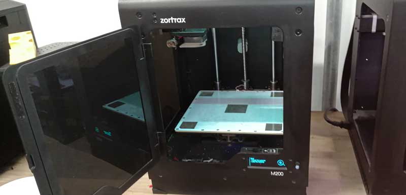 Picture 72.2.
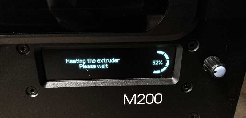 Picture 72.3.
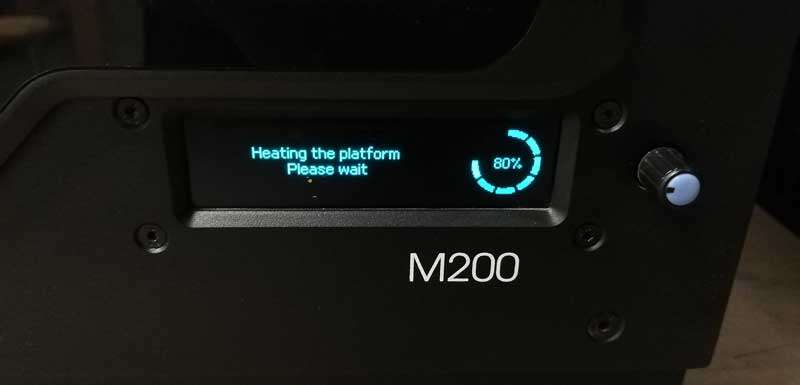 STEP 3.
 Print the test
Picture 72.4. Picture 72.5.
 Picture 72.6.
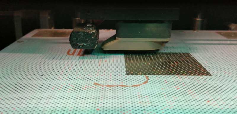 Picture 72.7.
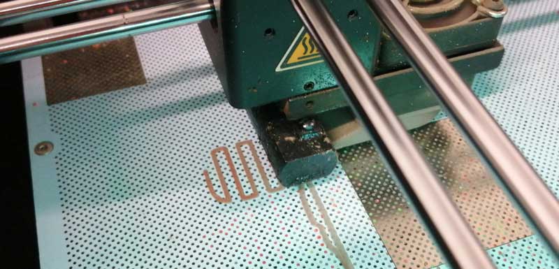 Picture 72.8.
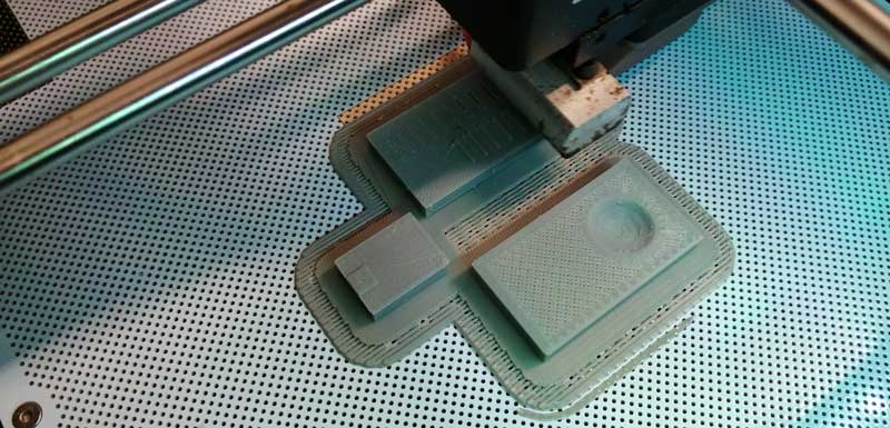 STEP .
View final
So, the 3D printer test results are: in (Image 72.9 and 72.10) the printing was more or less good, the result was fun at the bottom of the suspended angle, it has some shapes that resemble hair. because I printed it without support. On the other hand, in (Image 72.11) the result was successful and ended well. In the last image it was an interesting topic here because my partner and I decided to print one model for him and one for me of the same object, but with different configurations. Both were printed without backing material, but in the fill and in the resolution of the layer, the one with a 0.29 mm layer managed to print almost all the holes, but the one using a 0.09 mm layer, the result was that it printed less holes than the other and the finish is visually noticeable because the numbers are lighter on the object using a layer height of 0.09mm as expected.
Picture 72.9.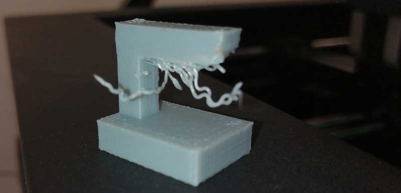 Picture 72.10.
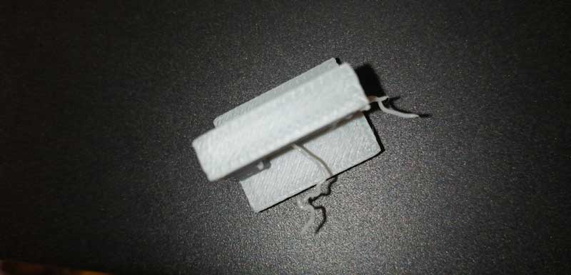 Picture 72.11.
 Picture 72.12.
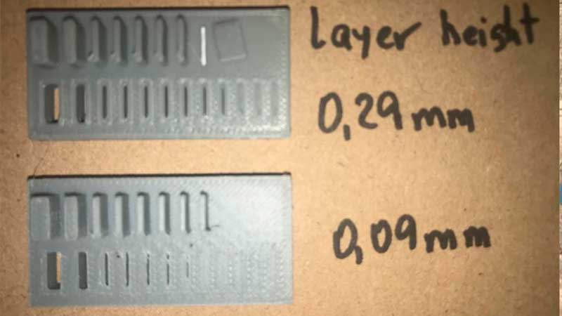
========== learned/conclusions ==========
This assignment was the easiest, because I already had experience in 3d design and printing but still learned things, tolerances and finishing. For example, in the support I made at the beginning, my instructor made me an observation that marked my life as a designer because I had not realized that when there are right angles it is more prone to break than a curved angle.
In the scan of my pokemon it was fun because I liked to see the operation of the scanner and to see the lights that the scanner emitted when scanning the pokemon.
=============== FILES ===============