For my final project I decide to built a Electronic Drum Kit because I was a drummer in high school, but I had to stop playing it because I was already starting university and also that it took up a lot of space and also that I didn't have time to play it, finally I had to give it to a friend who was interested in learning to play drums.
WHY I BUILT THIS?
With this project, I will help people acquire a good Electronic Drum Kit at a low cost and without taking up much space.
The best thing is that drummers who want to make their own drums can use my project as a starting point and can modify this electronic drum kit to their liking or improve it to make it cooler.
I give you a little information. A drum kit, also called a drums, box (short for "gadget") or simply drums, is a collection of drums and other percussion instruments, usually cymbals, that are placed on stands. to be played by a single player, with the drumsticks in both hands and the feet operating the pedals that control the hi-hat cymbal and kick drum and the kick beater.
.Standard modern equipment (for a right-handed player), as used in popular music and taught in music schools, contains:
-A snare drum, mounted on a stand, placed between the player's knees and played with drum sticks (which may include rutes or brushes)
-A bass drum, played by a pedal operated by the right foot, which moves a felt-covered beater
-Two or more toms, played with sticks or brushes.
-A hi-hat (two cymbals mounted on a stand), played with the sticks, opened and closed with left foot pedal (it can also produce sound with the foot alone)
-One or more cymbals, mounted on stands, played with the drumsticks
Normally to be able to play it you require a special room to use it, but some decide better to adapt the drums to an environment. To do this, they place bolsters inside the drums as well as pads on the heads to reduce noise, but personally this makes the drums less attractive.
HOW I MADE IT?
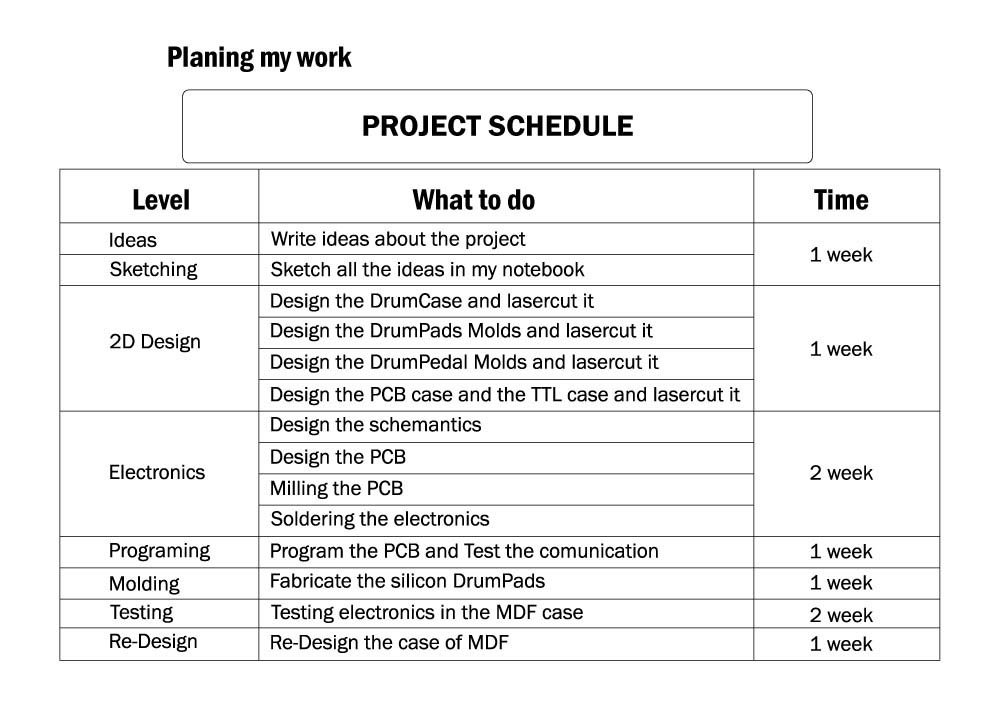
For my project I decided use three manufacturing means:
-LASERCUT
-MOLDING & CASTING
-ELECTRONICS PRODUCTION
Regards, Luis Tolentino
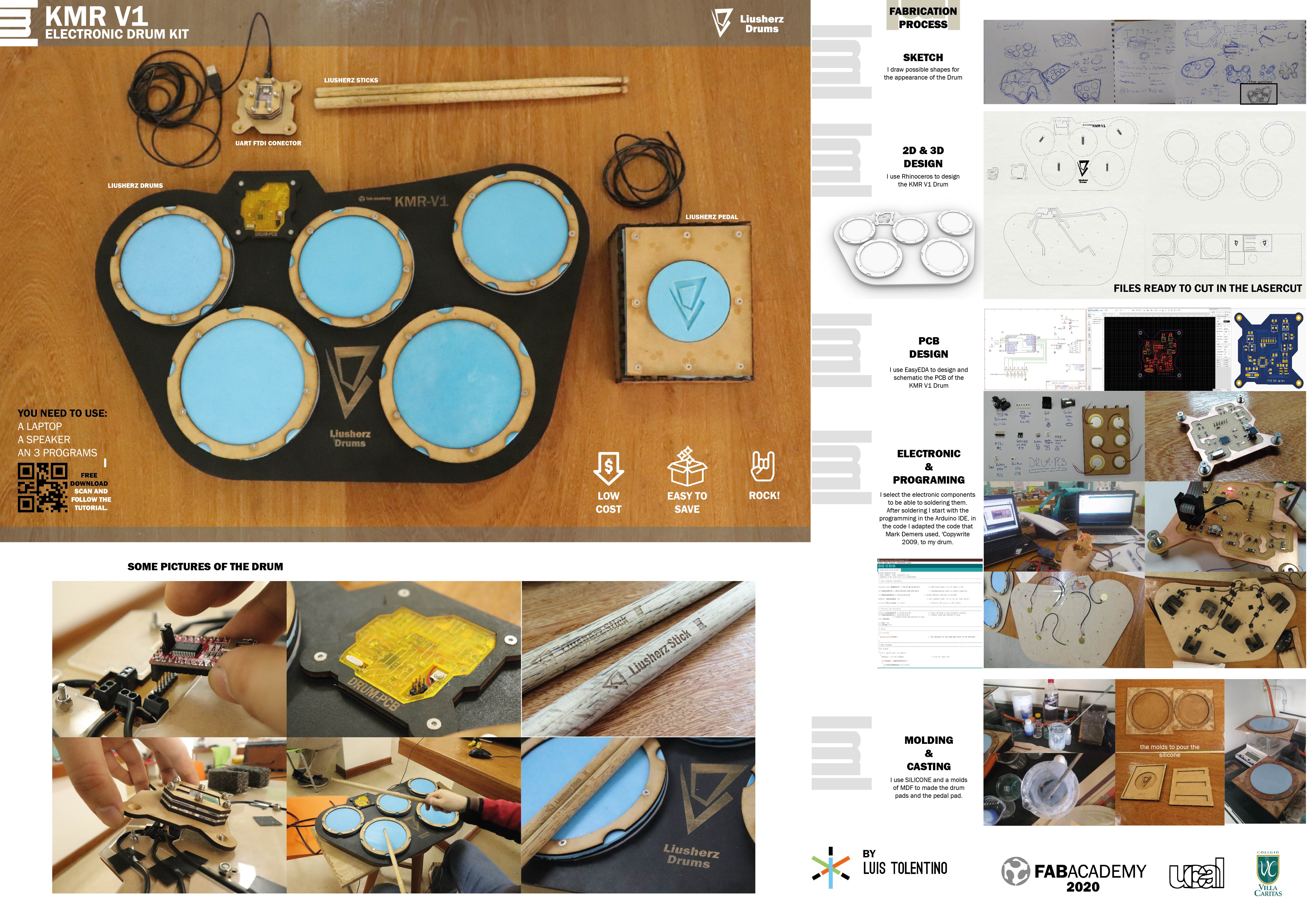
FABRICATION PROCESS
In the image below I show my gand.
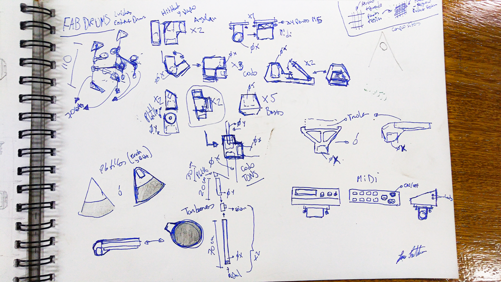
======== SKETCHES ========
For the design, I focused on the space the drum set occupies and also on the comfort when playing it.
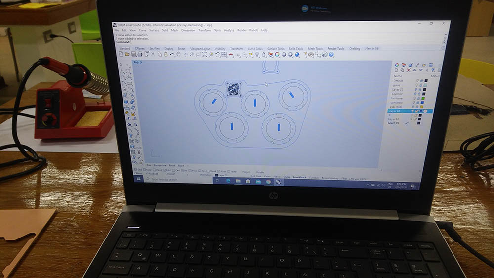
I start to make a Desktop Electronic Drum-kit, I passed my idea to the Rhinoceros program because Rhino has allowed me to observe in detail how to assemble the parts for my project and it is also a good design software.
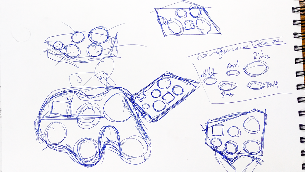
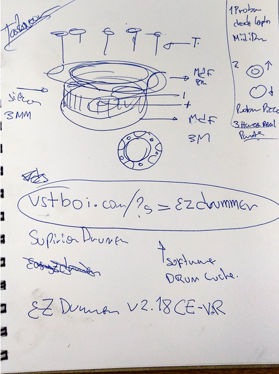
Picture F1.0. This are my first sketches, in this picture I show my first design of my Electric DrumKit. This drum have five drums and three cymbals. Picture F1..1. In this picture and the next picture I show the distribution of my ideas of my Electric DrumKit. Picture F1.2. This are the design was I desided to build. Picture F1.3. from this picture to picture f1.7.
I show my designs and ideas of how to assemble and make my Electric Drumkit. Picture F1.4. Picture F1.5 Picture F1.6 Picture F1.7.
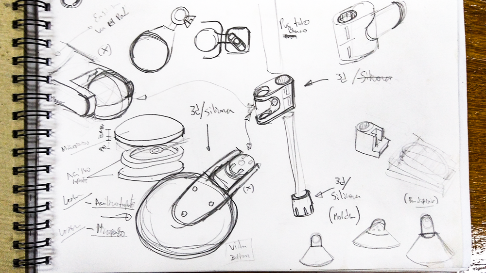
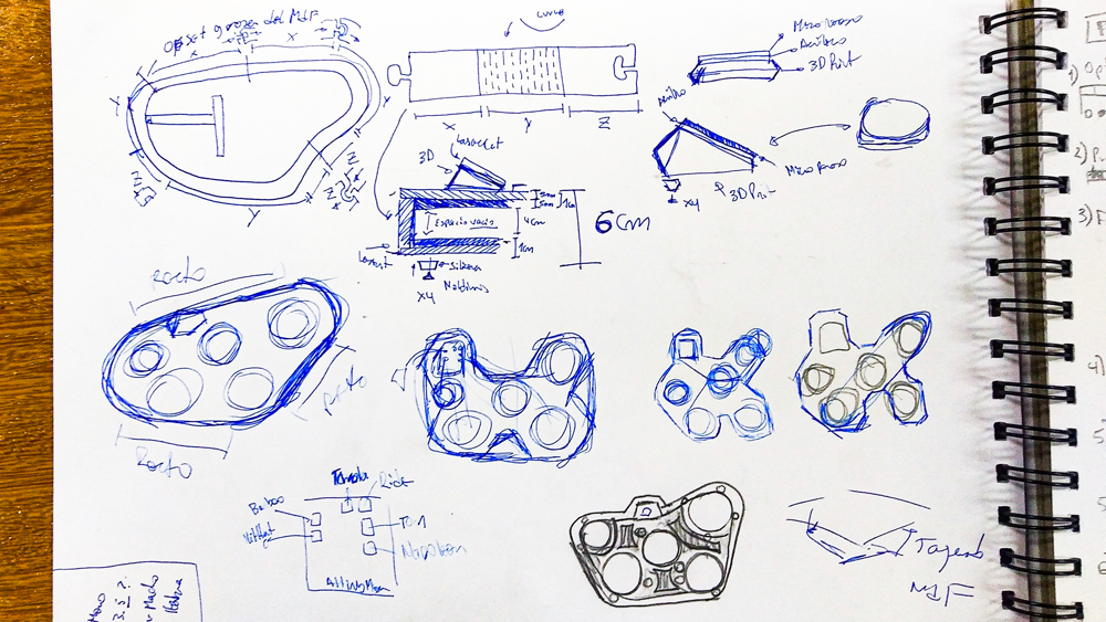
Due to lack of time due to quarantine I had to modify my drum, for this new idea I start to make a Desktop Electronic Drum-kit, I passed my idea to the Rhinoceros program because Rhino has allowed me to observe in detail how to assemble the parts for my project and it is also a good design software.
============== STEP 1. ==============
-Design and Drawing-
I show my new design sketch. For this drum I fabracted in lasercut.
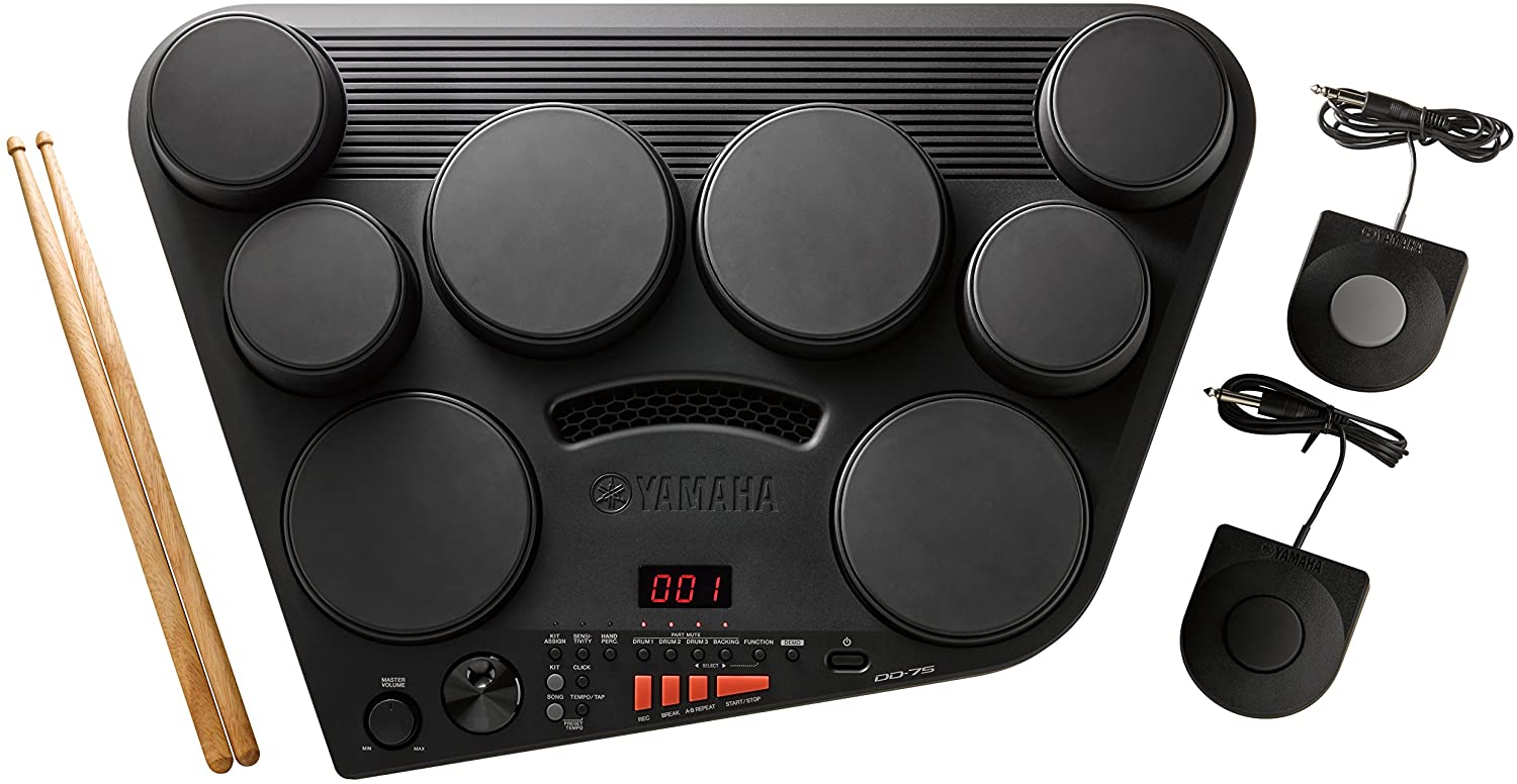
Picture F2.0. I inspire in this drum. Yamaha DD-75 because its design is compact and easy to store. Plus I've played on one of these drums. Picture F2.1. In my design I prefer to give it some wider pads and make it easy for me to play them when you are rocking. Picture F2.2. Picture F2.3. In his picture I show a sketches of the trace of the cables of the KMR-V1 drum. Picture F2.4. In picture is my my idea to asmble my drum pads.
============== STEP 2. ==============
-Design and draw my new design in Rhinoceros-
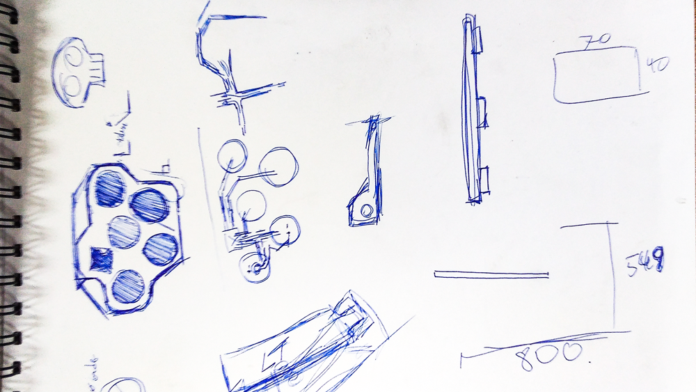
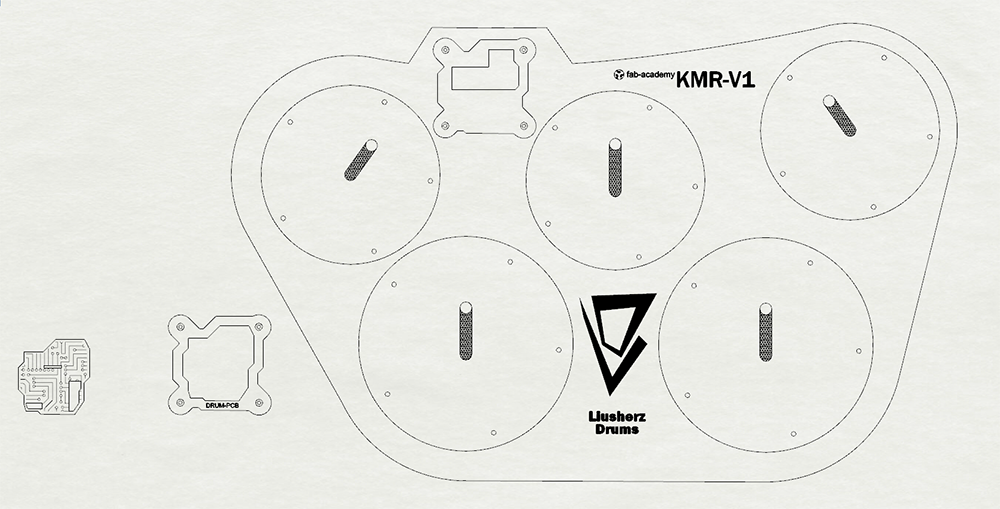
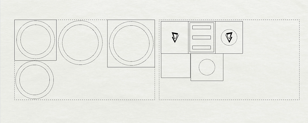
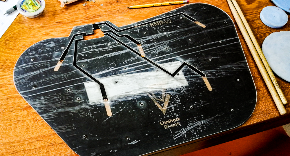
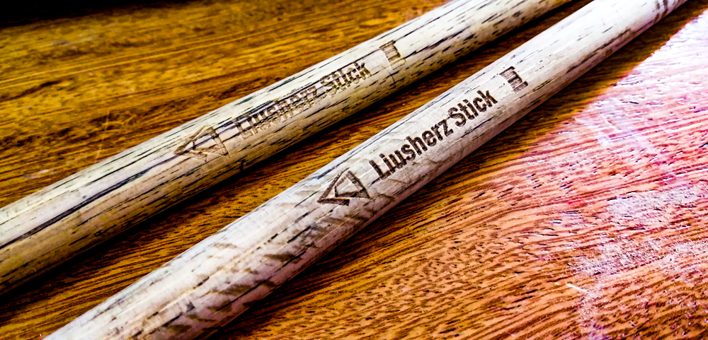
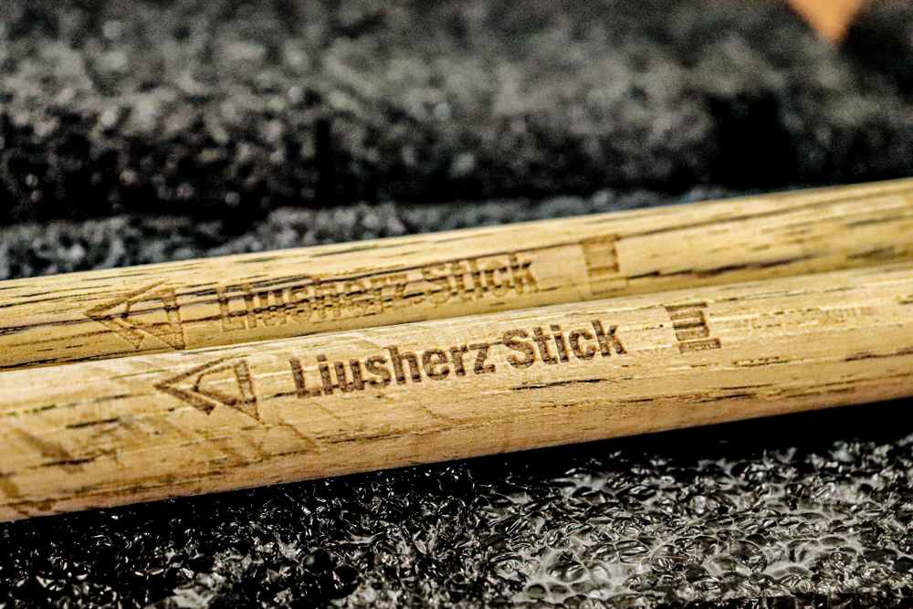
Picture F3.0. This are my final design of my Drum. I called KMR V1, the V1 it means version1. And I made a brand Liusherz Drum. Picture F3.1. In this picture I show my molds for my drum pads of silicone. Picture F3.2. This are a screenshot of my design ready to cut in the lasercut macjine. In the left region are the molds of my drum and In the right region are my pedal parts mold. Picture F3.3. In this picture I show my molds already manufactured. Picture F3.4. This are my already manufactured pedal molds. The left mold is the foot pad aand the right is the bottom mold pad. Picture F3.5. This are the border of the pads and the holes for the screws M3. Picture F3.6. this are the board of the trace of the cable of the piezo pads.This board will be made of acrylic
This are a 3D view of my Drum KMR-V1.
========= FABRICATION =========
In previous weeks, I made a model of the drums with the CNC cutter, but it did not go very well, thanks to this I was able to improve the final design in Rhino. As I changed the design for the COV19, I modified and corrected some errors that happened to me when I cut CNC. For this new design of my drum I will only need three manufacturing means: Laser Cut - Molding - Electronic Production. With these three means I can easily assemble my drum. For all the design I will use the Rhinoceros program which when the design is finished correctly, I will then generate the dxf files that will allow me to manufacture the parts of my drum.
STEP 1: Lasercut making the base, drums pads and the pedal.
For first step I decided to made a protipe in cardboard. But I have a problem. I show below.
Video FV1.0.
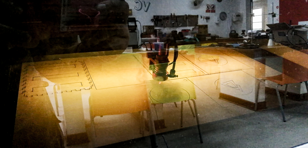
Picture F4.0. I have a burn problem, my setting of the laser was wrong so I burn my cardboard. Picture F4.1. Picture F4.2. Picture F4.3. Picture F4.4.
So I corrected my configuration and changed the material that I used in the prototype and I preferred to make the official one that would be in MDF and I also decided to paint the MDF in black. This is the manufacture of my drum in the Lasercut machine. Picture F5.0. Picture F5.1. Video FV1.1. In this video i document the cut of first board that is the base of my drum.
Video FV1.2. In this video I document the cut of the second board that is the acrylic board.
Video FV1.3. In this video I document the cut of the third board that is the tops of my drum pads.
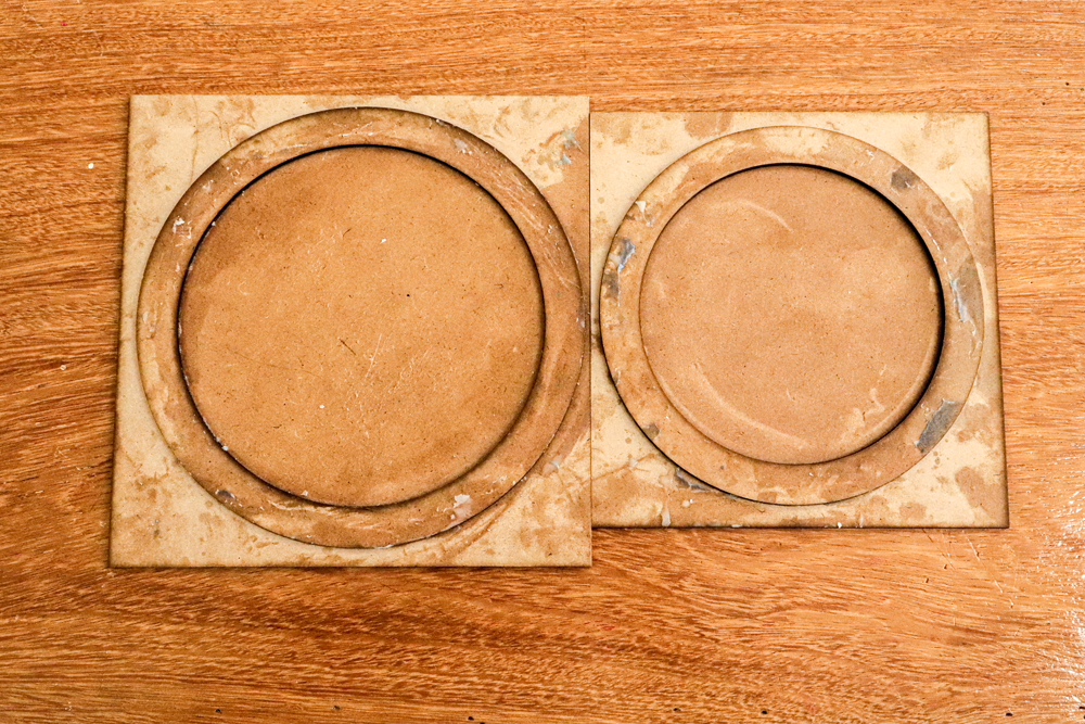
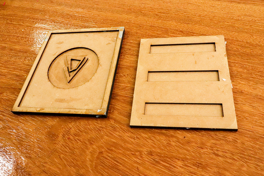
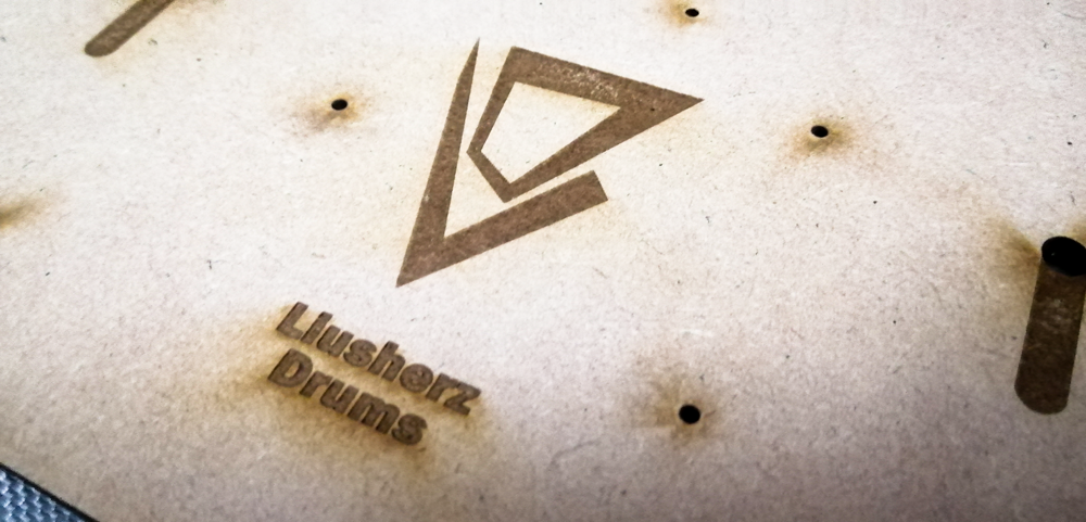
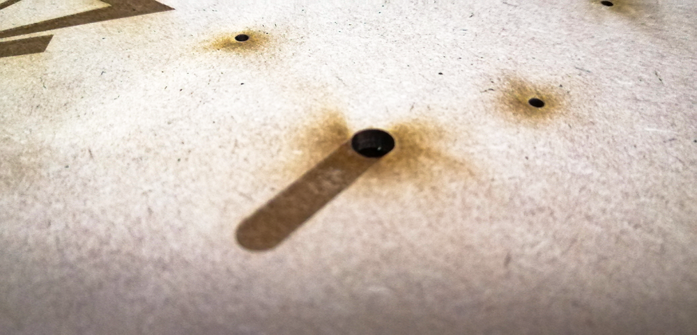
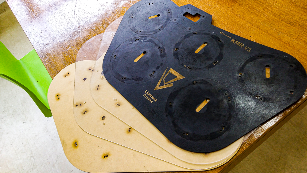
This pictures below is my final result of my cut. Picture F6.0. In this picture I show my Brand was i designed to this proyect. Picture F6.1. This are the holds when i passed the cables of the piezos to the PCB. Picture F6.2. In this picture show the first and second board final. Picture F6.3. In the place we I made my drum I dont have acrilyc of 5mm so I decided to made two boards of acrilyc. In this image below, I show all the boards that I made and put them in order as they would be to assemble my drum. Picture F6.4. In this picture I show my cut of my pedal. Picture F6.5. This is the acrylic window that goes in the PCB case.
Here are the MDF files ready to cut int the lasercut machine: Drum-Files
Here are the acrilic files ready to cut int the lasercut machine: Acrl-Files
STEP 2:Molding the pads of my DrumKit in silicon molds.
Well, I really enjoyed this step because I personally like to do molding and casting. So I made my drum pads out of silicone. Because the silicone absorbs the sound of the hit and also increases the bounce of the club when hitting the pads.
I do a test of rebound and sound absorption for this I made a mold to make a pad to test my theory.
Picture F7.0. For the mold I decided to recycle as it is a test mold I decided to use a roll of tape that I ran out of and glued it to a circular MDF base. Picture F7.1. I do the same as in the wildcard, brush all surfaces of the mold with vaseline. the mold is somewhat improvised just for testing. Picture F7.2. Picture F7.3. So we be are, I finally to made the proof pad.
Video FV2.0. Here are the test of my theory. My theory was fine and works perfectly.
In this step I molding the oficial pads in silicon, so in the pictures bolow I show the process I have to fabricate the molds and the pads for my DrumKit.
-PEDAL MOLD and PAD-
In the picture below for the F8.0 to the F8.8 I show the fabriaction for the pedal mold and the silicon pad.
Picture F8.0. I paste the lasercut pizes to build the mold. Picture F8.1. This the final view for my pedal pads. Picture F8.2. In this picture I show the silicon pad process. Picture F8.3. I have a secret mix. I used 100g or Silicon F-20 and 15g of the catalizer and 2g of ink. This mix have faster dry. Picture F8.4. This are the catalizer I used. Picture F8.5. So when I finish the mixture well, I pour it into the mold carefully covering the entire mold evenly. Picture F8.6. A normal drying lasts 6 to 8 hours but with my secret mixture I dry it in 3 hours. In the picture I show the top pad of my pedal. Picture F8.7. In this picture I show the bottom pad of my pedal. I decided to put a silicone pad on the base of the pedal because I wanted it to be non-slip and it worked. Picture F8.8. Pedal final view.
-DRUM MOLD and PAD-
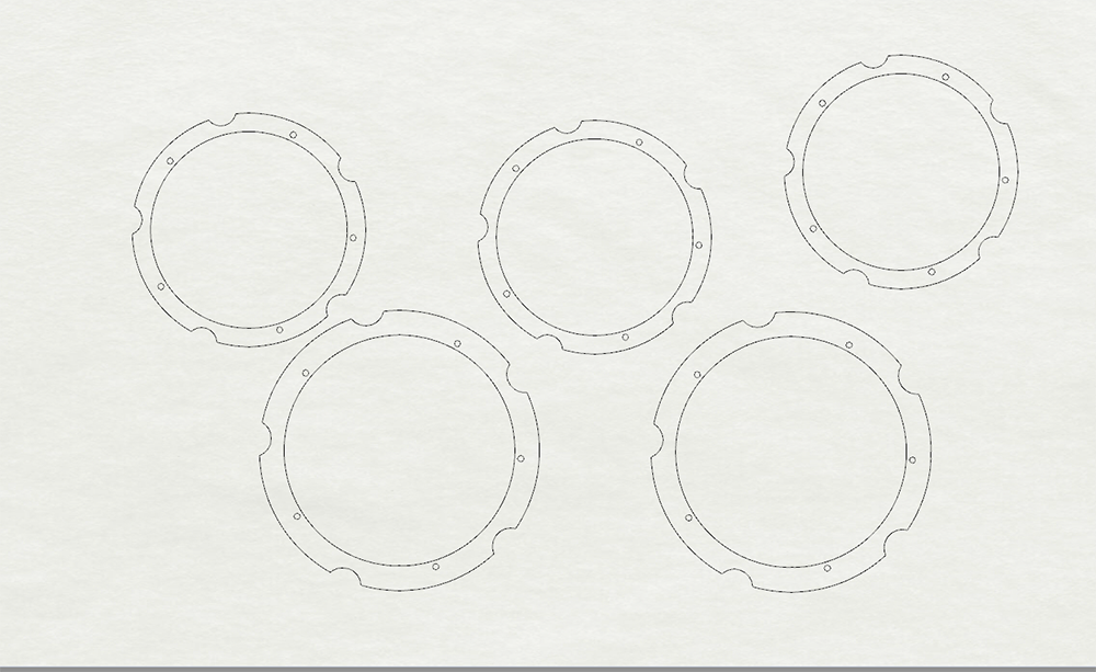
In the picture below for the F8.10 to the F8.18 I show the fabriaction for the drum mold and the silicon pads.
Picture F8.9. This are the two molds I have to fabricate the pads of silicone. Picture F8.10. In this image below up to F8.12, I pour the silicone into the two molds and wait for it to dry and repeat the procedure, twice in the large mold and three times in the small mold. Picture F8.11. Picture F8.12. Picture F8.13. Once dry, he took it out of the mold and cut off the excess. Picture F8.14. After checking that everything is fine, with the help of a dremel I cut the corresponding holes of the pads. So step to drill 5 holes. Picture F8.15. In the photo below I show when I put the bolts in the 5 holes. Picture F8.16. I join the mdf edge with their corresponding pads and attach the 5 bolts with 5 washers in the holes. Picture F8.17. In the image below, I show the pads in their respective places. Picture F8.18. In the image below I show the final result of my drums.
STEP 3.PCB Fabrication.
But first I need to know the pinout of my attiny mega and my ISP conector. Below are the pictures of the pinouts.
Pinout.1. This is the my ATMEGA 328 pinout. Pinout.2. And this is the ISP pinout I used the & pin IDC.
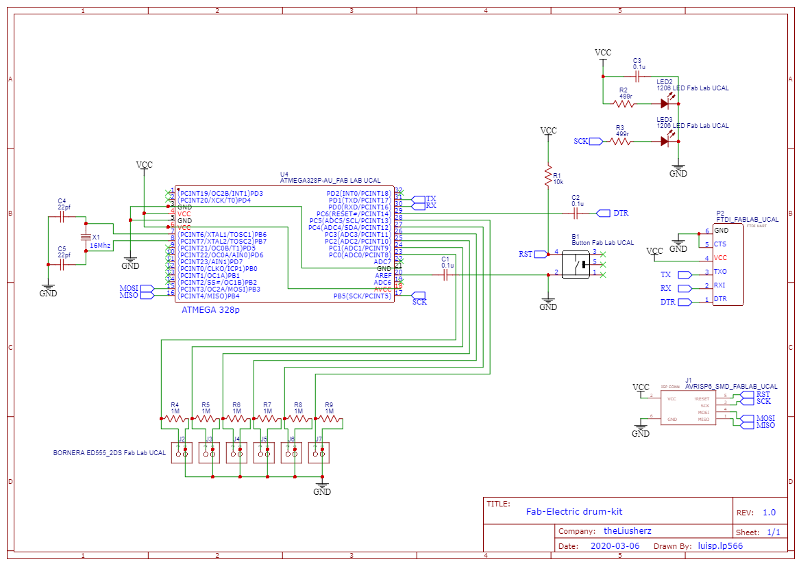
For the electronic I use EasyEDA to schematic and PCB my circuit. Below are the steps.
-Draw and trace in EasyEDA-
In EasyEDA I draw my schematic and trace my PCB circuit. Picture F9.0. Here are my file of my schematic: Schematic PDF.
Once I have finished making my schematic, I step to draw and trace my pcb.
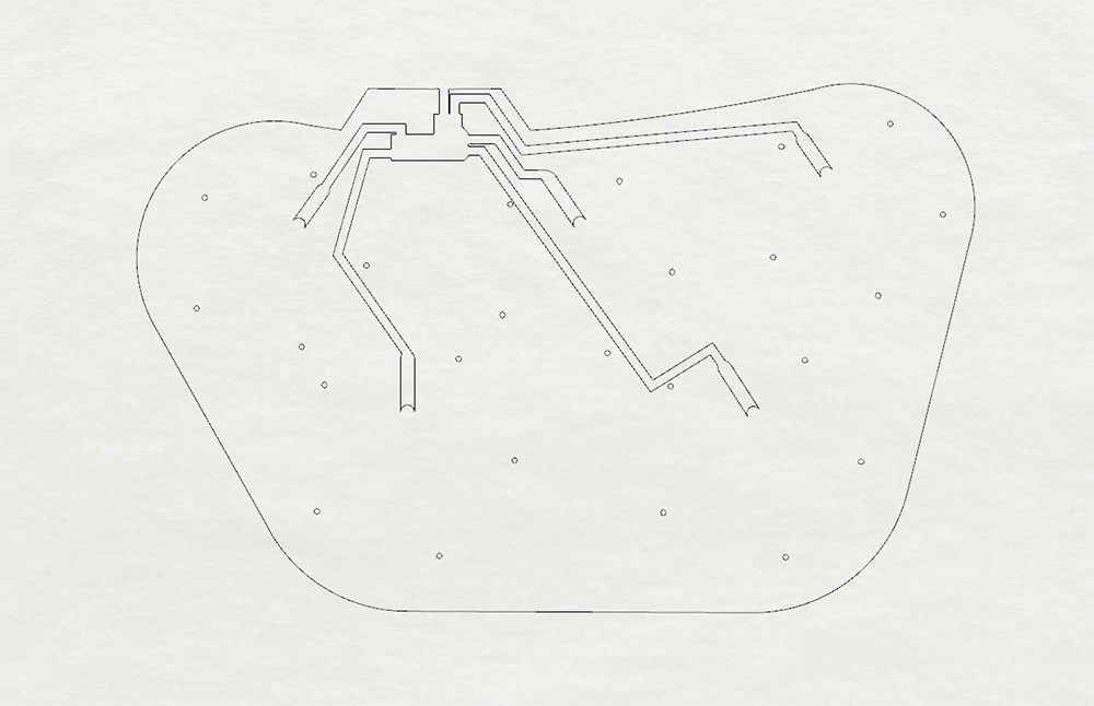
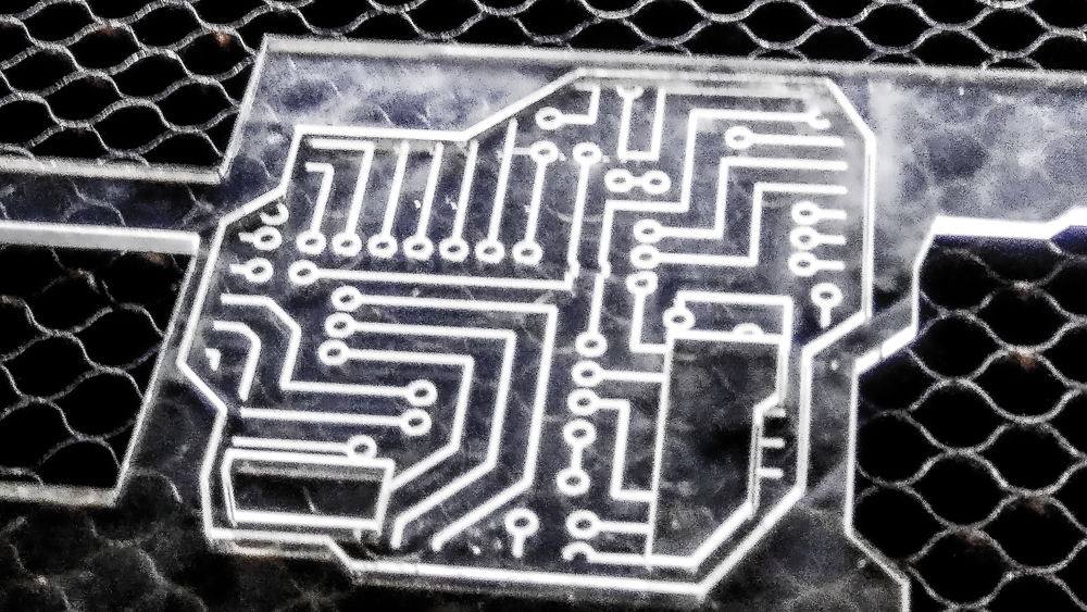
Picture F9.1. This step was very difficult, because I had to think a lot and it was difficult to connect all the components correctly tracing the entire PCB in addition to creating a layout for my PCB. Picture F9.2. This are the preview view of this PCB. This is the PCB that I mill and use on my drum. Picture F9.3. In the previous PCB there were two errors, one of the errors was that at one point in my schematic the connection of the reset pin was not correctly traced and the other is that my FTDI was obstructed by the terminal board. So I had to modify the PCB. Picture F9.4. This are the preview view of this PCB. Picture F9.5. This is my final layout of my PCB. Unfortunately I could not mill it. Picture F9.6. This are the preview view of this PCB.
-Export Gerber and open in FlatCAM-
Once the trace of my PCB is finished, I export the Gerber files from EasyEDA. To later open them in FlatCAM, prepare my PCB for milling. Picture F10.0. In the picture below I show my traced open in FlatCAM. Picture F10.1. Trace Picture F10.2. Outline. Picture F10.3. Holes
-Electronics Componets I need to used on my PCB Circuit-
Picture F11.0. In the picture below I search the componets I need to used in my PCB.
This are the list of material I need to build my all Drum.
Product name
Unit price
Units
Subtotal
ATMEGA 328 P-AU
s/.12.00
1
s/.12.00
2x3 Pin Conector
S/3.00
1
S/3.00
1x6 Pin Conector
S/3.00
1
S/3.00
AVRISPS6-SMD
S/2.00
1
S/2.00
LED 1206
S/1.00
2
S/2.00
RESISTORS 499R
S/1.00
2
S/1.00
CAPASITORS 0.1U
S/1.00
3
S/1.00
ED555 2DS
S/1.50
6
S/9.00
RESISTORS 1M
S/0.80
6
S/4.80
CRYSTAL 16MHZ
S/1.00
1
S/1.00
CAPASITORS 22pf
S/0.50
2
S/1.50
BUTTOM
S/2.00
1
S/2.00
RESISTOR 10K
S/1.00
1
S/1.00
MDF
S/15.00
6
S/90.00
SILICON F-20 PLUS
S/
1
S/
SILICON catalizer
S/
1
S/
MACHINABLE WAX
S/.
1
S/
TTL FT232
S/.17.00
1
S/.17.00
CELLULOSE PCB BOARD
S/.20.00
1
S/.20.00
TOTAL
-
38
S/167.30
Picture F11.1. This are the componets I need to soldering into my PCB.
-Milling the PCB-
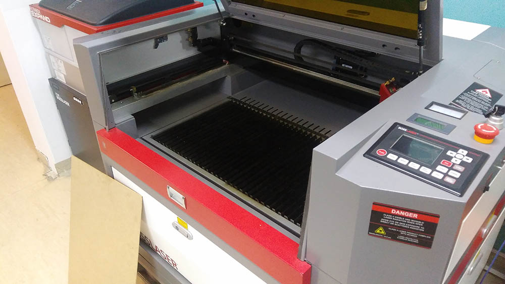
Video FV2.0. First I mill the trace and used a endmill 1/64".
Picture F12.0. Picture F12.1. Picture F12.2. I clean the dust with a brush and gently remove the dust from the milling to be able to see the result of the milling and if there is an error to correct it. Picture F12.3. Picture F12.4. After cleaning the PCB I check that all the trace is fine. Picture F12.5. Picture F12.6. I carefully checked the PCB and I see that the milling Trace went very well. Picture F12.7. To mill the holes I change the endmill 1/64" to the 1/32". Video FV2.1. Second I mill the holes.
Picture F12.8. In the image below I show you the holes. Video FV2.2. Third I mill the outline.
Picture F12.9. Picture F12.10. Once the milling is finished, I clean it with the brush. Picture F12.11. With the help of a scalpel, clean some residues in the traces. Picture F12.12. This are the final view of my PCB. Picture F12.13.
Video FV2.3. Once the total milling is finished, I use a multimeter to verify that all the traces are correct.
-Soldering the PCB-
Picture F13.0. The first componet to I solding is the Atmega328. Picture F13.1. Picture F13.2. Picture F13.3. Next I solding the other componets. Picture F13.4. The holes where my TTL connection goes came out small so I decide to repair it using a dremell.
Picture F13.5. I fixed it. Picture F13.6. Once my PCB is repaired I finish soldering all components. Picture F13.7. This is the top of my PCB. Picture F13.8. This is the back of my PCB.
Debbuggin the PCB
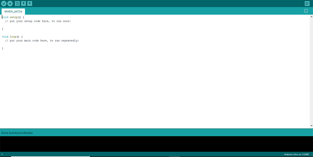
For this I burn bootloader code on the DRUM PCB.
Screenshot 1. Everything's alright. YEAH!
========= ELECTRONIC =========
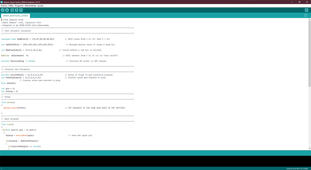
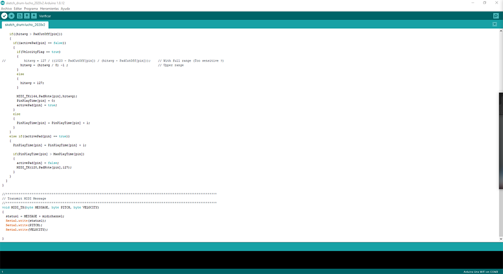
STEP 1. Programming the PCB Drum. lml yeah!
Picture F14.0. Video FV3.1. First step of programming.
Picture F14.1. I upload a blink to my PCB using the Arduino IDE. Picture F14.2. It's works!. Picture F14.3. Then I try connecting a piezo to my PCB and see if it works. Picture F14.4. It's works!. Video FV3.2.
Picture F14.5. Picture F14.6.
Video FV3.2.
Video FV3.3.
Picture F14.7. I try conect my PCB to a TTL FTDI, but ist'n woked.
For this I test the drum kit complete. I hope all be alright Below are the steps.
STEP1 Connection of the DrumKit to the PC.
Picture F2.3.
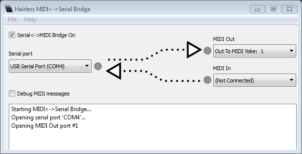
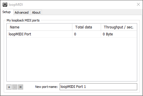
In order for my drum to work I need to have these programs: The main program is ZDrummer2 and these secondary ones are just as important without these my DrumKit does not work: Hairless-MIDIserial, loopMIDIsetup and ASIO4all 2. And this software is not vital is called pocketMIDI, which I it allowed to visualize the recognition of the hits that it gave in the pads to be able to modify and correct any problem. I'll leave the links below.
SOFTWARES
Here are the links to the software I need to make my drum work properly.
-For the sound and effects I used ZDrummer2 This software allows me to customize the sounds that the drums make to my liking. The ZDrummer2 default gives me a few libraries if I want more I can find more on the internet.
I view this video in youtube to download and install the ZDrummer2 on my computer.
And here are the link. ZDrummer2
-Here are the link of the program for the reduce the latence when I hit my pads of my drum. Is a plugin to ZDrummer. ASIO4ALL2
-Here are the link of the of download of the way to connect
serial devices (like Arduinos) to send and receive MIDI signals. Hairless MIDIserial
-Here are the link of the software can be used to create virtual loopback MIDI-ports to interconnect applications on Windows that want to open hardware-MIDI-ports for communication. LoopMIDI
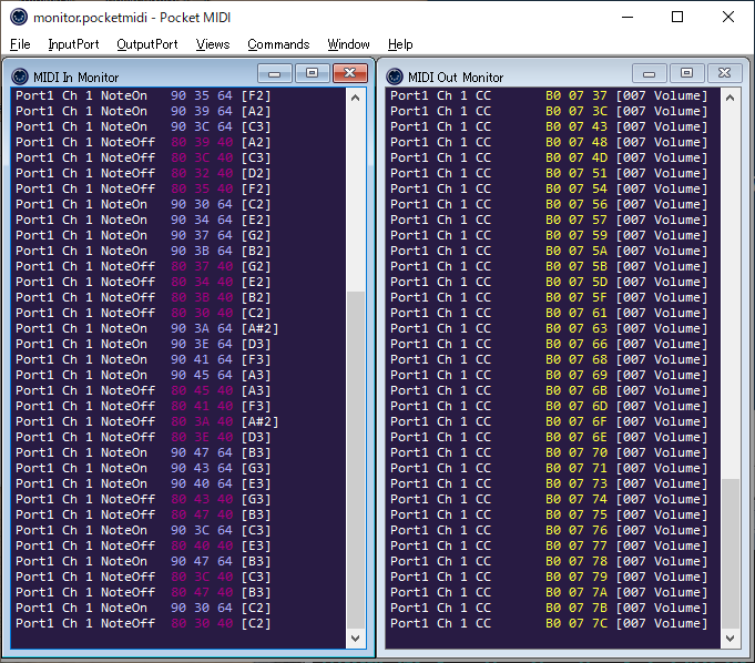
-Here are the link of the software MIDI monitoring tool for connect your MIDI instrument to computer using a USB or USB/MIDI adapter and you can monitor MIDI messages to and from your instrument in real time.. PocketMIDI
COMUNICATION Video FV*.0. In this video I show the communication between my PCB and my PC, by touching the Piezos, making the previously mentioned softwares installed on my PC recognize the blow and emit a sound.
In this part I show my all complete DrumKit conected to my PC to recognize the blow and emit a sound like a real drum. Picture F2.3. Picture F2.3.
So! This if it was an adventure of the most extreme !. but I learned many things. one of them is to review well before going to the next level this frees me from many problems. I don't like me because because I didn't check my schematic well, I had to do a surgical operation on my pcb, I had to do this because we had the time to spare and it didn't give me the chance to have another one.
But I also learned how to assemble and manufacture pieces to join them later, for this it is very good to know the widths of the materials and diameters of the bolts or screws to use.
In this aasigment I managed to get my secret formula for quick silicone preparation achieving the result I require, greater rebound and greater sound absorption.
Then I learned how to connect my drum with my laptop using special software.
And the code ... this part was extensive, it was the one that took me the longest, since I had to understand that each drum is a binary code that the software I use recognizes and I had to link that value from my IDE to my drum.
This assignment was the most challenging and laborious, reneges until I almost gave up because it didn't work. But despite all this, it served me as a life lesson to not give up and to achieve what I want to achieve to be!


.jpg)
.jpg)
.jpg)
.jpg)
.jpg)
.jpg)

.jpg)
.jpg)
.jpg)
.jpg)
.jpg)
.jpg)
.jpg)
.jpg)
.jpg)
.jpg)
.jpg)
.jpg)
.jpg)
.jpg)
.jpg)
.jpg)
.jpg)
.jpg)
.jpg)
.jpg)
.jpg)
.jpg)
.jpg)
.jpg)
.jpg)
.jpg)
.png)
.png)
.PNG)
.PNG)
.PNG)
.PNG)
.PNG)
.PNG)
.png)
.PNG)
.PNG)
.PNG)
.jpg)
.jpg)
.jpg)
.jpg)
.jpg)
.jpg)
.jpg)
.jpg)
.jpg)
.jpg)
.jpg)
.jpg)
.jpg)
.jpg)
.jpg)
.jpg)
.jpg)
.jpg)
.jpg)
.jpg)
.jpg)
.jpg)
.jpg)
.jpg)
.jpg)
.jpg)
.jpg)
.jpg)
.jpg)
.jpg)
.jpg)
.jpg)
.jpg)
.jpg)
.jpg)
.jpg)
.jpg)
.jpg)
.JPG)
.JPG)
.png)
.jpg)
.jpg)
.JPG)
.JPG)
.JPG)
.JPG)
.JPG)
.JPG)
.JPG)
.JPG)
.JPG)
.JPG)
.JPG)
.JPG)
.JPG)
.JPG)
.JPG)
.JPG)
.JPG)
.JPG)