In this task I was delayed because I had no physical parts to practice and do this task, it took me almost two weeks to find the components since in my country it is still quarantined by covi19, it was difficult for me to find sellers but searching and asking I managed to obtain three sellers with which I managed to supply with a good variety of equipment and electronic components to create my projects from home.
For this task, complete three circuits on three difficulties, one simple one intermediate and the other complicated. I want to emphasize that the topic of electronics and robotics is a new topic for me, but it is something that I like and it caught my attention as a child so I learned these days watching tutorials and asking my friends to teach me until my aunt who is an electrical engineer. While watching my tutorials I was thinking what I could do for this task so it occurred to me to make a circuit that produces sound, also an integrated system of LED lights for a helmet that I have and finally a rotating platform. The steps and documentation of these circuits are shown below.
Single-Task
======== Output Circuits ========
So, I show you my circuits I make: a ciruit that produces sound, also an integrated system of LED lights for a helmet that I have and finally a rotating platform.
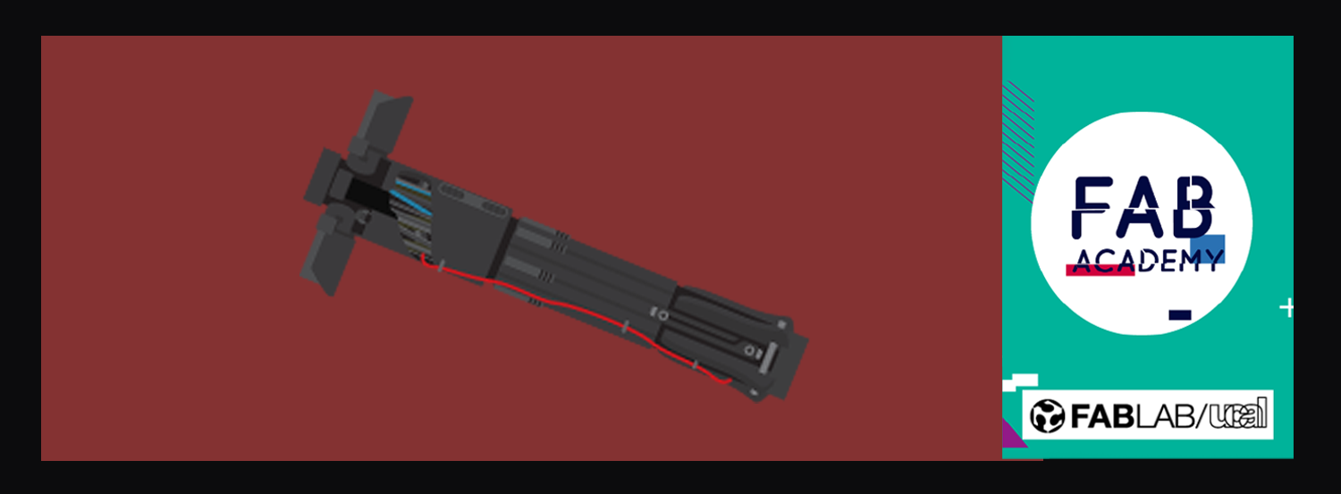
Circuit that produces a StarWars sound
I made a personaly fan exercide a ciruit what make a sound of the imperial march of StarWars.
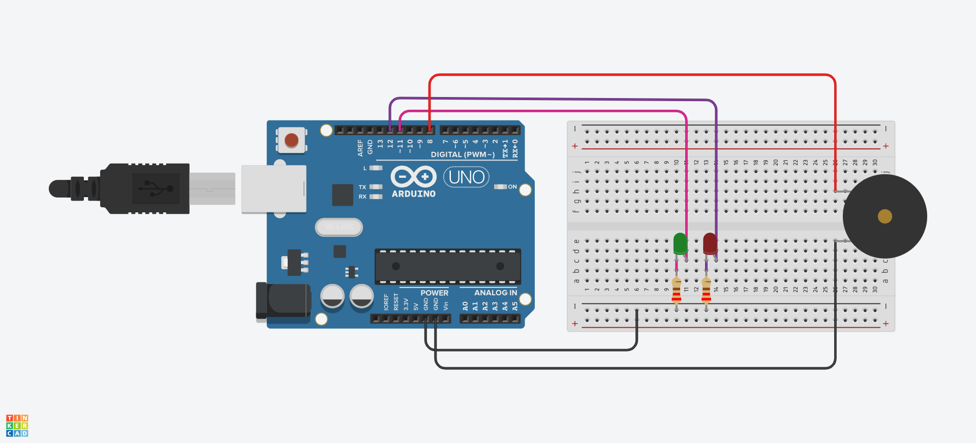
I used for made this circuit
1 RED LED, 1 GREEN LED, 1 pasive buzzer 1 resitor 220Ohm 1 arduino UNO 1 breadboard and Jumper cables
STEP 1. Desing in Thinkercad. Picture 90. Designing in Tinkercad is very easy. So I search for the components I require for my Vader PCB and try to do a virtual simulation.
Video.Simulation
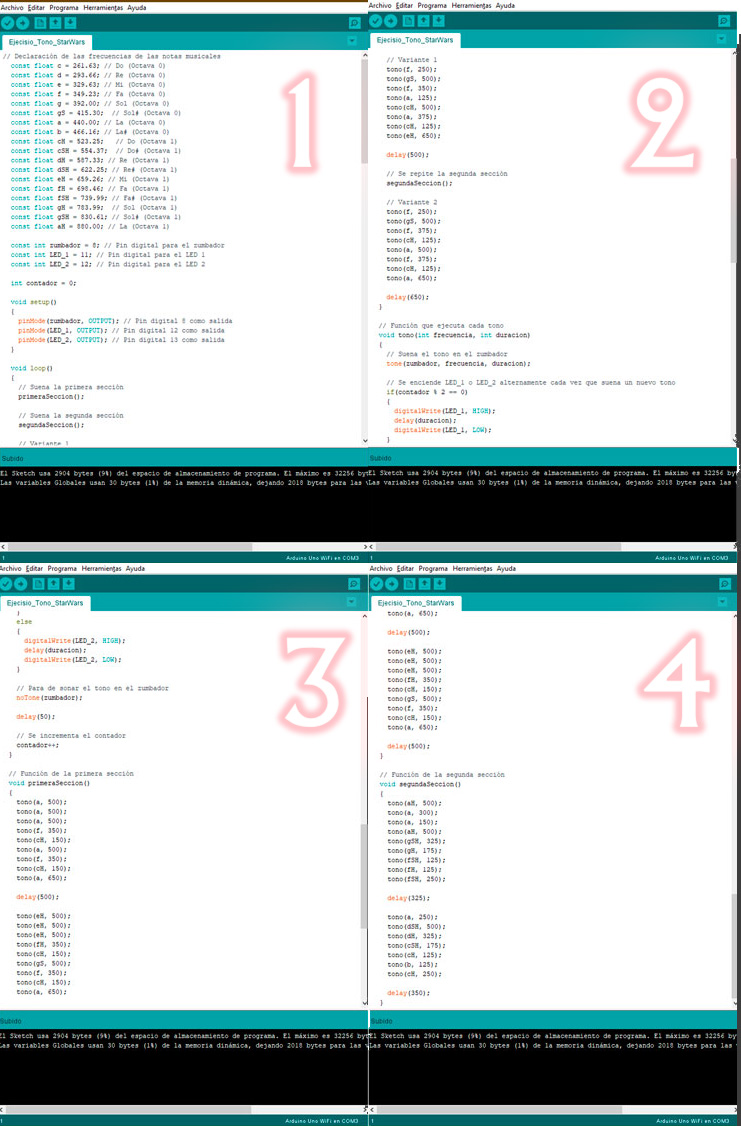
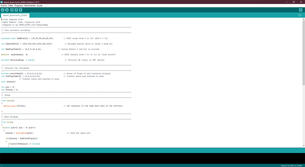
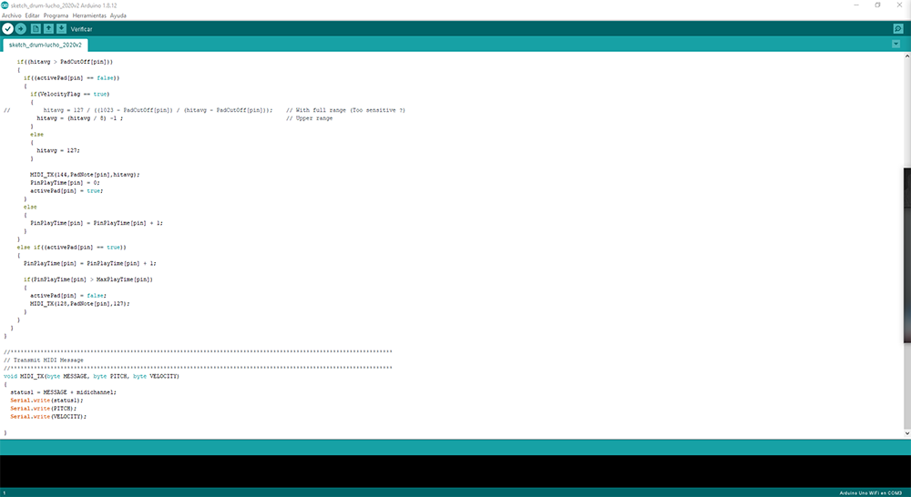
STEP 2.Code
Picture 90.1. The code was more complicated since it incorporates notes and melody. For this my instructor suggested that I investigate how to do it. But I found that someone had written an open license code online so I read a tutorial to understand the syntax of the code and then adapt it to my Circuit.
STEP 3. EasyEDA
Picture 90.2. To design Vader's silhouette, I first opened rhinoceros and exported the svg (Image Below). Then erase everything that was inside leaving only the silhouette.
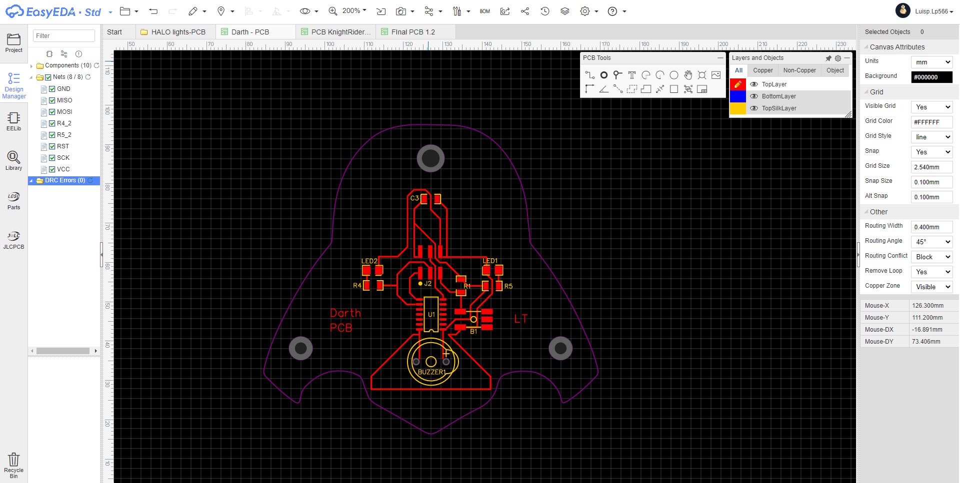
Picture 90.2.1 Finally, import the dxf file of Vader's silhouette into EasyEDA where I can design the complete circuit. In the image below I show you my final result.
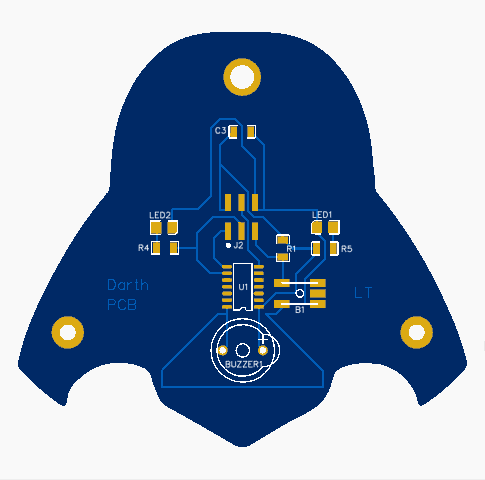
Picture 90.3. This would be a preview of my Vader PCB. Ready to mill.
STEP 4. Milling of my Vader PCB and soldering of the electronic components on my Vader circuit PCB.
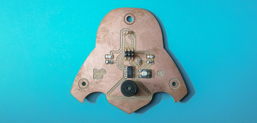
But for this part due to time constraints due to Covid blocking, I could not finish, I only managed to mill and weld it but later I realized that it had some flaws and I could no longer improve it because I preferred to focus on my final project that also covers that task .
Picture 91.1. I share what I did and what it looks like is the image below..
But I recreate my Vader circuit using an Arduino and a breadboard along with these electronic components: 1 RED LED, 1 GREEN LED, 1 passive buzzer, 1 220 Ohm resistor, and male male jumper wires
STEP 1. So I assemble my circuit and this is the final view of my circuit using Arduino.
Picture 90.4. Picture 90.4.1. Picture 90.5.
Video.01 Here I share a video with the final demonstration of my circuit with arduino and breadboard recreating my Vader PCB.
DESIGNING THE ELECTRONICS
In my final project the output device part this is what I did. I show you some images, but I leave this link for you to see more about the process of the project. Final Project.
-------. DESIGN THE PCB .-------
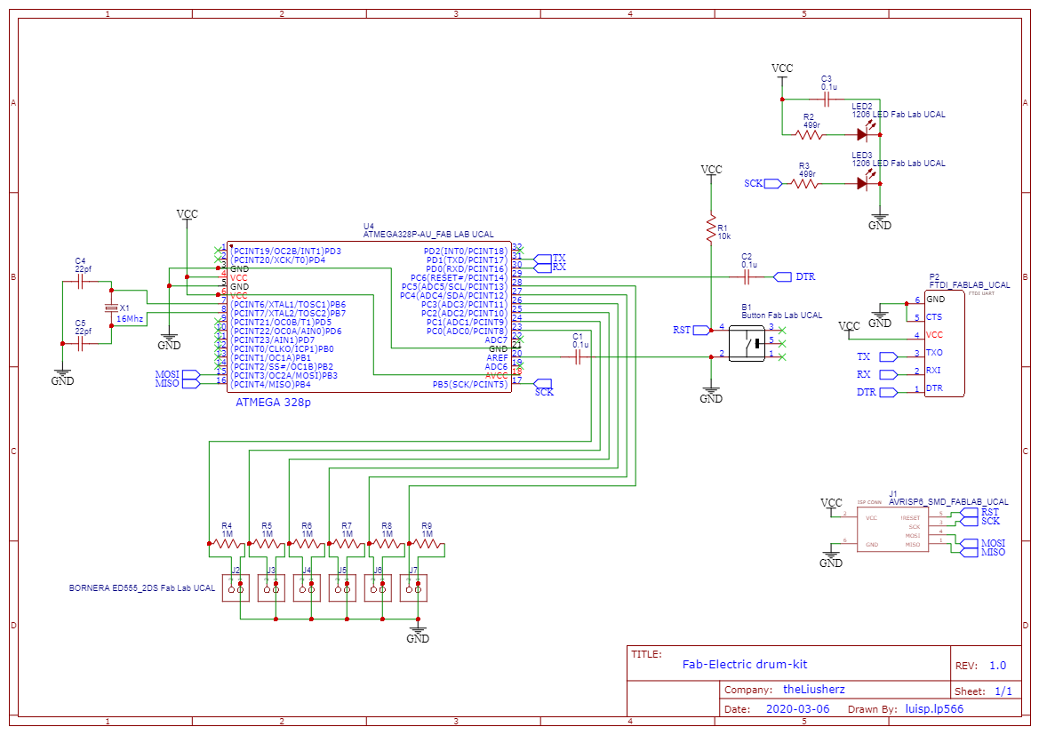
In EasyEDA I draw my schematic and trace my PCB circuit.
Picture DMS2.0. Here are my file of my schematic: Download.
Once I have finished making my schematic, I step to draw and trace my pcb.
Picture DMS2.1. This step was very difficult, because I had to think a lot and it was difficult to connect all the components correctly tracing the entire PCB in addition to creating a layout for my PCB.
Picture DMS2.2. This are the preview view of this PCB. This is the PCB that I mill and use on my drum.
Export Gerber and open in FlatCAM
Once the trace of my PCB is finished, I export the Gerber files from EasyEDA. To later open them in FlatCAM, prepare my PCB for milling.
Picture DMS2.3. In the picture below I show my traced open in FlatCAM.
-------. MILLING THE PCB .-------
Picture DMS3.0. I open the roland mill software and configure it to mill the trace from my PCB.
Video FV2.0. First I mill the trace and used a endmill 1/64".
Video FV2.1. Second I mill the holes.
Video FV2.2. Third I mill the outline.
Picture DMS3.10. This are the final view of my PCB.
-Electronics Componets I need to used on my PCB Circuit-
Picture DMS1.0. In the picture below I search the componets I need to used in my PCB.
Picture DMS1.1. This are the componets I need to soldering into my PCB.
-------. SOLDERING THE PCB .-------
Picture DMS4.0. The first componet to I solding is the Atmega328.
Picture DMS4.6. This is the top of my PCB.
Picture DMS4.7. This is the back of my PCB.
Debbuggin the PCB
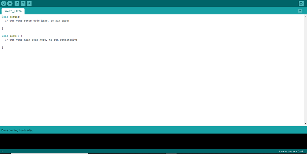
For this I burn bootloader code on the DRUM PCB.
Screenshot 1. Everything's alright. YEAH!
This is the part of output.
========= ELECTRONIC =========
STEP 1. Programming the PCB Drum. lml yeah!
Picture F14.0. This Is my final PCB. Picture F14.1. I upload a blink to my PCB using the Arduino IDE. Picture F14.2. It's works!. Picture F14.3. Then I try connecting a piezo to my PCB and see if it works. Picture F14.4. It's works!. Video FV3.2.
Picture P1.0. I upload to my PCB and incidentally I will test the communication with the respective software.
Group-Task
======== Osciloscop ========
In this group assignment we had to measure the power consumption of an output device.
To complete this course we use a gear motor. First, the no-load output was 0.12 mA. After applying a certain force (with load) to the motor, the resistance increased to 0.36 mA.
No load gearmotor test - 0.12 mA
========== learned/conclusions ==========
In this assignment, I learned how to connect an output device to a microcontroller board that I designed and program it to do whatever. It was very exciting to see a PCB designed by you come to life when programmed and see it respond to your needs. programming. When I designed the Vader PCB and had it made in my hands they don't know how excited I was so much so I didn't realize it had errors and I had to re-read it that made me sad, but when I designed my KMR-V1 PCB and programmed it and tested it. , and it worked and responded to your programming. I yelled out of emotion. In summary, I learned two things to review the design well in Easy EDA so as not to waste time in correcting and redoing, also that material is used, especially the endmill. The other thing I learned was to program and understand that each electronic component has its own special way of programming.


.jpg)
.jpg)
.jpg)
.PNG)
.PNG)
.PNG)
.jpg)
.jpg)
.jpg)
.jpg)
.jpg)
.jpg)
.jpg)
.jpg)
.jpg)
.jpg)
.jpg)
.jpg)
.jpg)
.jpg)