STEP 0. Design and drawing in a paper.
Firstly we draw a sketch of the tables.
Picture 22. 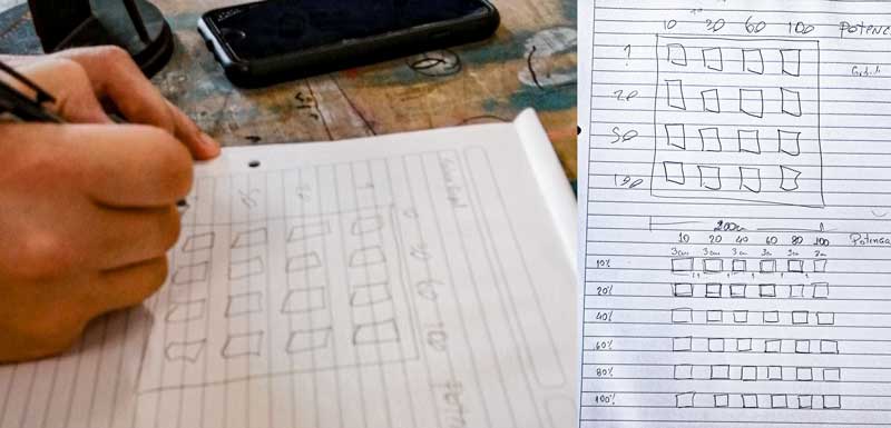 STEP 1.
 Draw in
Rinoceros.
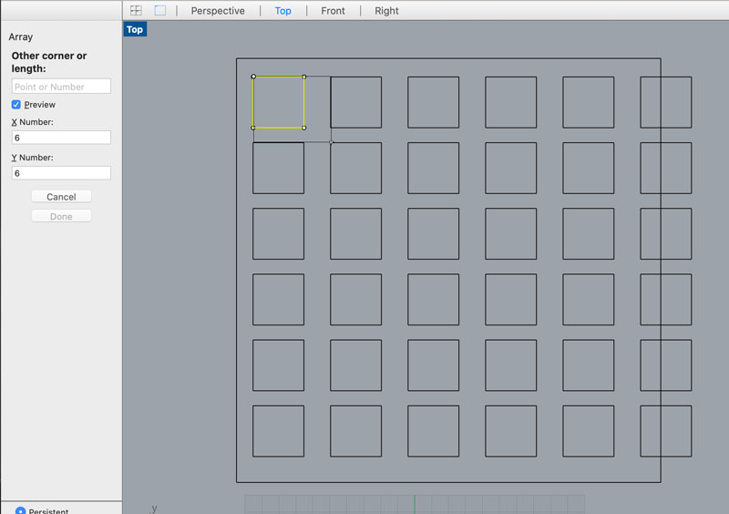
First we use the command rectangular array due to the squares as shapes chosen.
Picture 23.0.  Picture 24.0.
 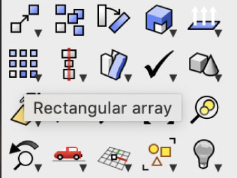 STEP 2.
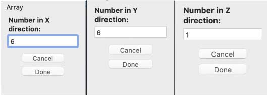
 Write the dimensions of the square.
Picture 25.0. We write the dimensions in X axis, Y axis and because it is a 2D drawing, Z has to be 1.
 STEP 3.
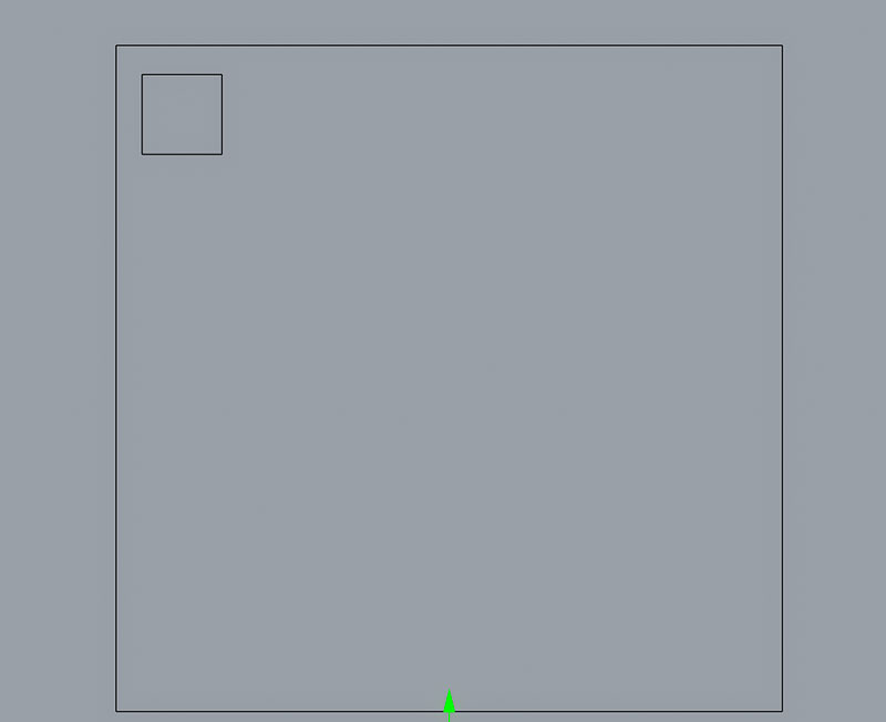
 Make the tables.
Picture 26.0. Here the first square we draw in Rhino.
 Picture 26.1.
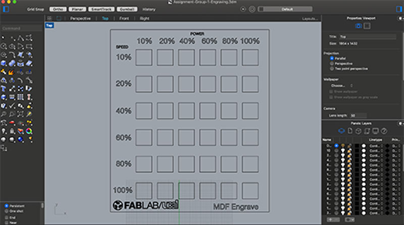
 Then we multiply it by 36 because we use 06 columns and 06 rows.
 Picture 26.2.
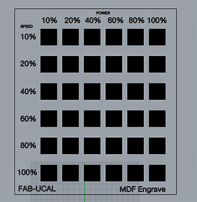
 We establish the columns for the power ranging from 10% to 100% and the rows from 10% to 100%, both parameters for engraving.
 STEP 4.
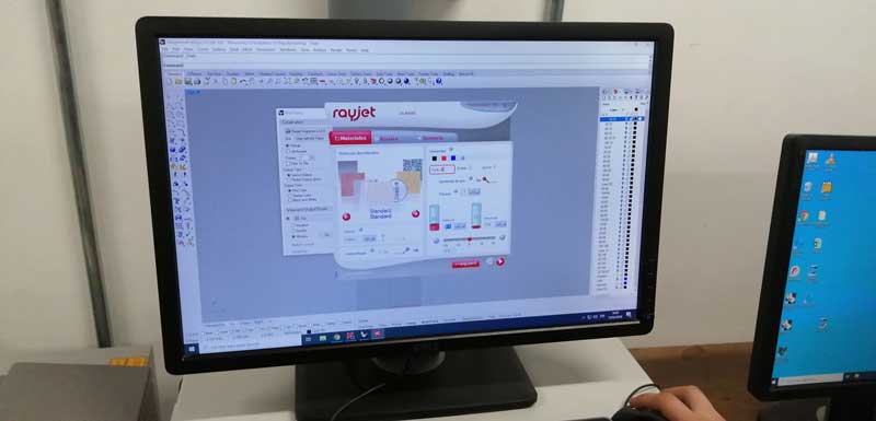
 Upload to the
Trotec software.
This step was to prepare the drawing to be cut with the Trotec Laser .
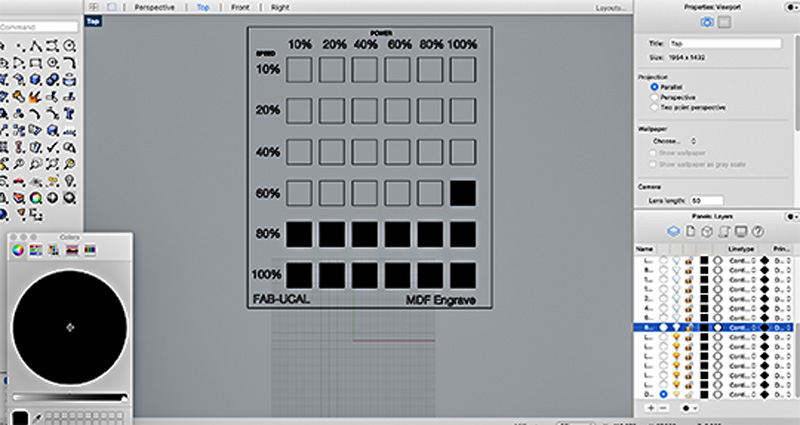
Picture 27. We have to hatch the squares that are going to be engraved, by creating layers. Each square is going to be cutted at a specific power and speed, so we have to create 36 layers one for each square.
 Picture 27.1.
 After that we have to add the layer for cutting the border and a layer for the text.
 Picture 27.2.
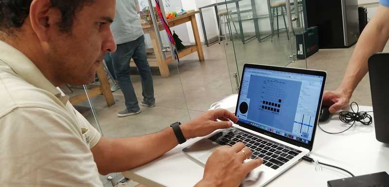 Picture 27.3.
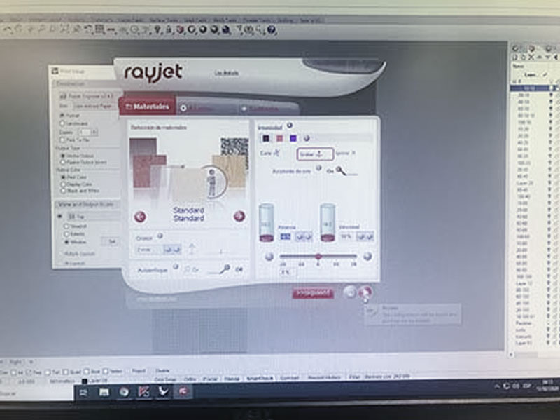
 Then we have to setup the information in the Trotec laser cutter.
 Picture 27.4.
 Here we learn to use different color either for cutting, marking or engraving. We write the first power which is 10% and speed to 10%.
 Picture 27.5.
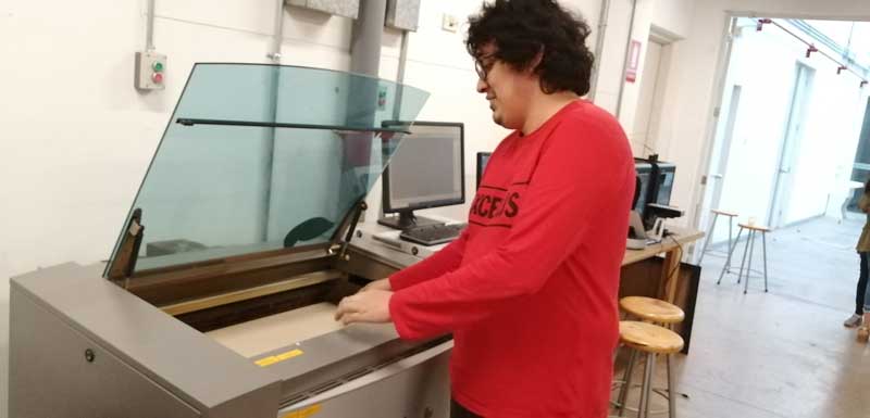
 Calibrating the Trotec Laser: First I turn the laser cutter and the filter on and then we start to focus manually
 STEP 5.
 ENGRAVE.
After, we gave the order to the laser machine to start doing the marking process and it did it well. Then we start the engraving process but something went wrong.
ERROR!
We realize that we use the template model of cutting for
Engraving(Picture 28).
Picture 28.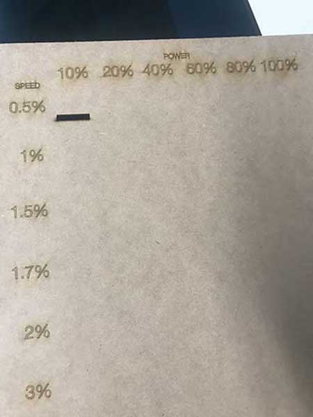
-Here we suggest to focus in the work.- It was night and probably the tiredness was playing tricks on us. So, we start again using another 3.18mm MDF
(Picture 28.2).
Picture 28.1.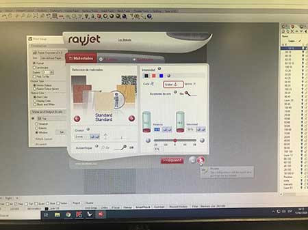 Picture 28.2.
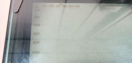 SURPRISE!
When the laser cutter start to
Engrave, we notice something really strange,
FIRE! (Picture 28.3). Using a power of 100% and a speed of 10%, during all the engraving process,
fire appears and at the end we noticed that the square has being
gone. (Picture 28.4 y Picture 28.5)
Picture 28.3. Picture 28.4.
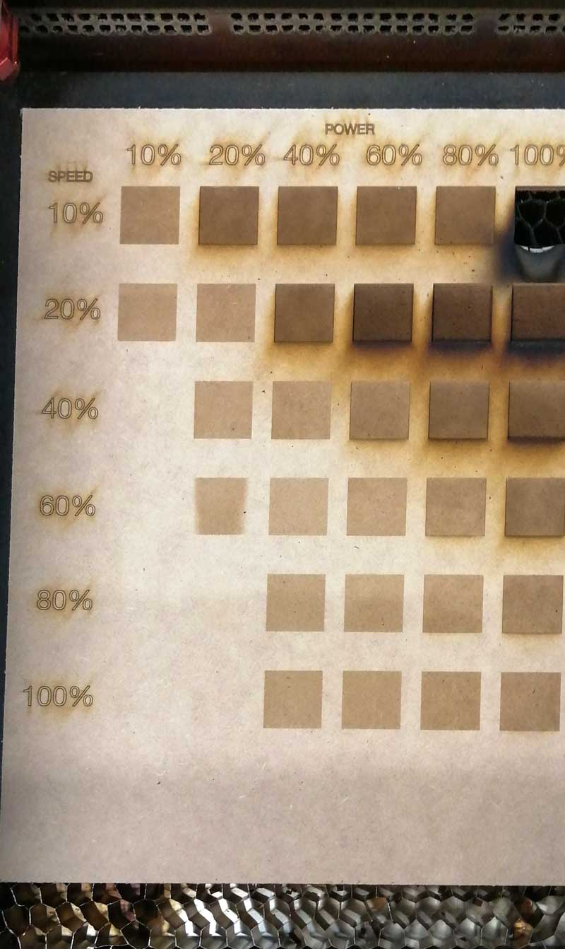 Picture 28.5.
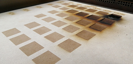 STEP 6.
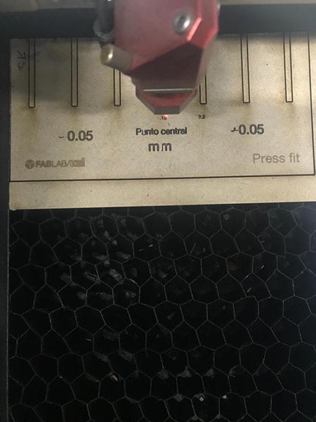
 CUT.
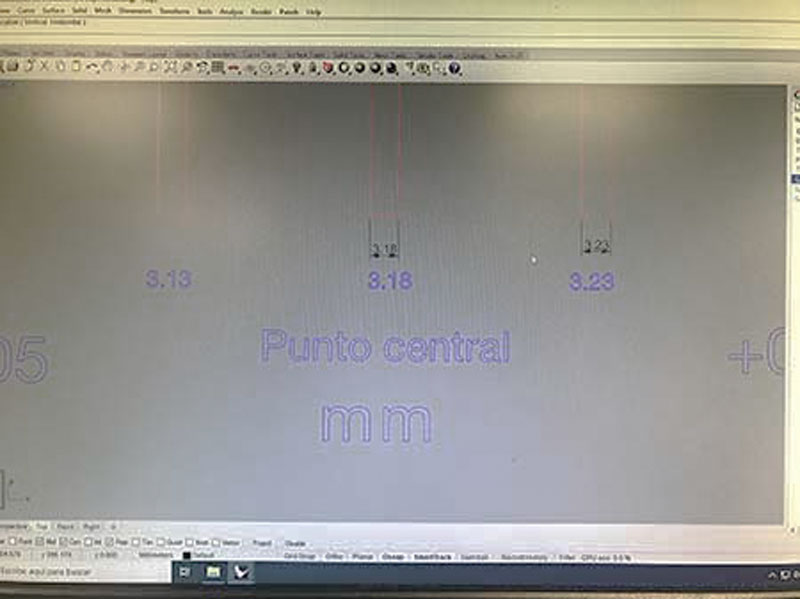
After engraving we continue to work with the cut process by changing the MDF table and the parameters in the software. We use:
-Power: 85% - 90% - 92% - 95% - 97% - 99%
-Speed: 0.5% - 1.0% - 1.5% - 1.75% - 2.0% - 3.0%
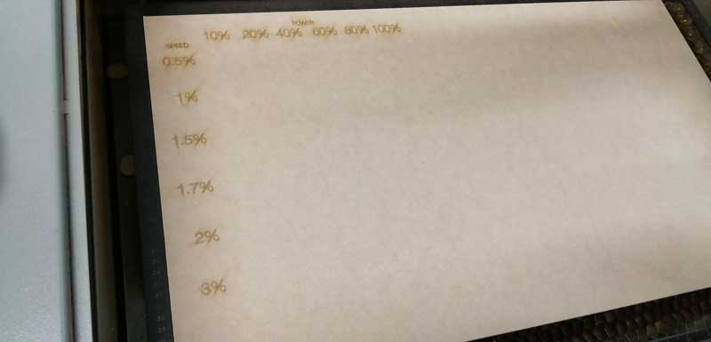
Then we test some of the squares to notice the difference in the mark left in the interior of the cut of each square. In the ones that uses more power there is a black spot
(Picture 29.4) and we have a video a share you below.
.
Picture 29.0.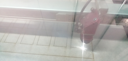 Picture 29.1.
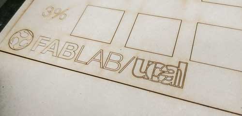 Picture 29.2.
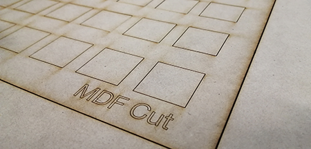 Picture 29.3.
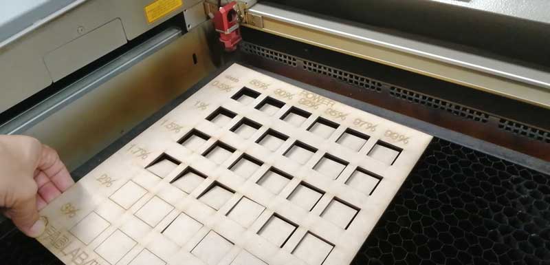 Picture 29.4.
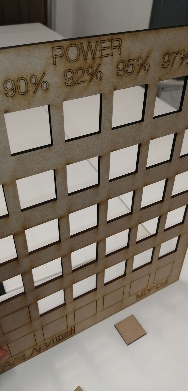 STEP 7.
 View final.
Picture 29.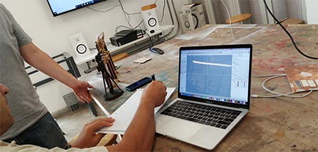 Picture 29.1.
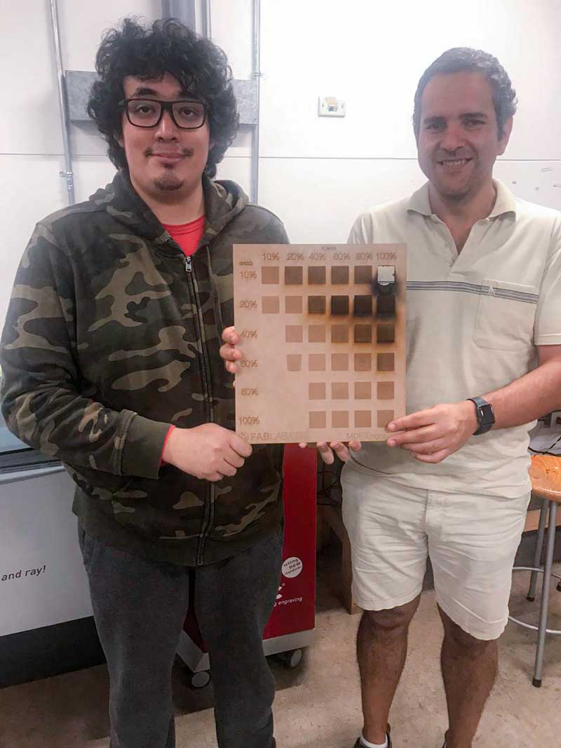 Picture 29.2.
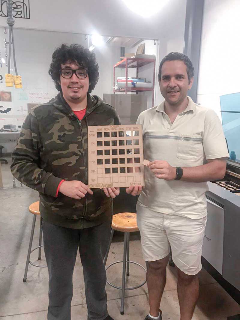
Vinylcuttter
For this assigmetn I decide sticker-cut for my notebook. I prefer use a diferent colors in this composition.
I use
Adobe Illustrator for do mi design, For me is a simple sofware and are simple to use. Below are the steps.
STEP 1. Design and drawing in
Adobe Illustrator
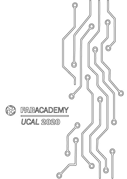
Using my knowledge in graphic design. I decide to make a geometric plot and circuit types.
Picture 33.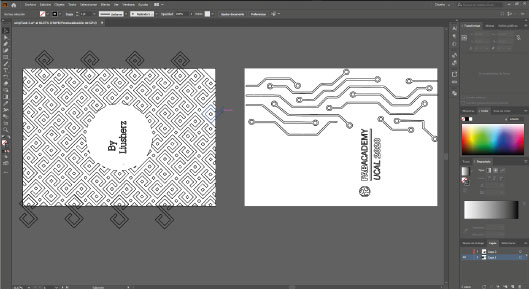
STEP 2. Finish my draw "
Cover and
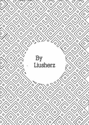
Backcover" vinyl stickers for my notebook.
Picture 34.0. Cover
 Picture 34.1. Backcover
STEP 3. Print my Vinyl-design
First put de stroke in 0.001
(Picture 35). Next prest
print or
ctrl+P and configure, search the pronter next change the
orientation and the
placement next press print
(Picture 35.0)
Picture 35.1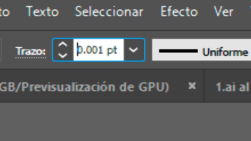 Picture 35.2.
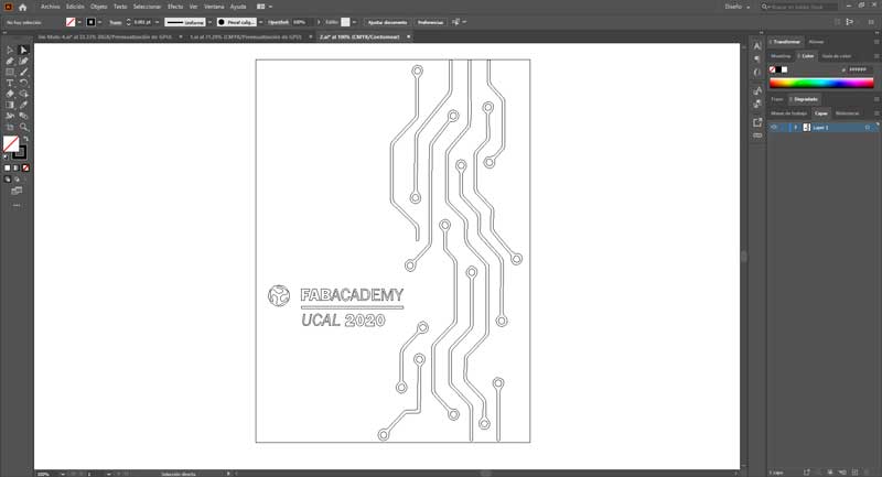 Picture 35.3.
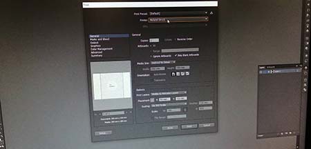
STEP 4. Cut the vinyl with two colors
Picture 36. In this picture I show my vinyl cut of my Backcover Notebook for thi cut I use a Grey vinyl.
 Picture 36.1.
 In this picture I show my vinyl cut of my Cover Notebook for thi cut I use a Black vinyl.
 Picture 36.2.
 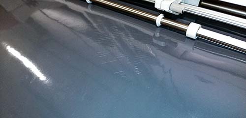 Picture 36.3.
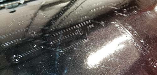
 In this detail image, I show how the vinyl will be after being cut. The only thing that cuts the vinyl cutter is the outline of our graphic, and then we go very carefully to remove.
STEP 5. Paste the stickers on my notebook
Prepare first the vinyl before to paste on my notebook. In the
(Picture 37) I retired the exes vinyl for my vinyl design, the result is the
(Picture 37.1 and
(Picture 37.2
Picture 37.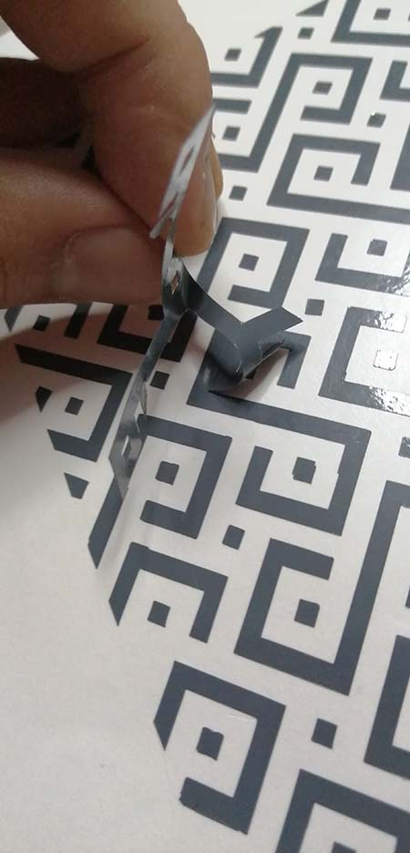 Picture 37.1.
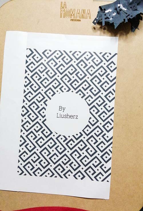 Picture 37.2.
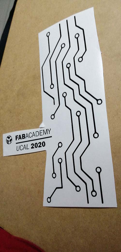
Next, I put over my vinyl design a transfer paper
(Picture 37.3). Next cut the size of my vinyl
(Picture 37.4). Last step is paste the paper trasnfer with my vinylcut over my notebook cover and backcover. and ritered the paper trasnfer carfuly
(Picture 37.4).
Picture 37.3.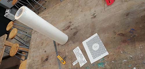 Picture 37.4.
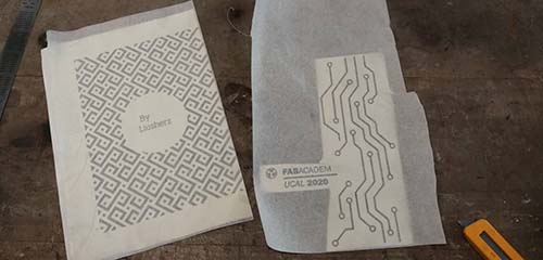 Picture 37.5.
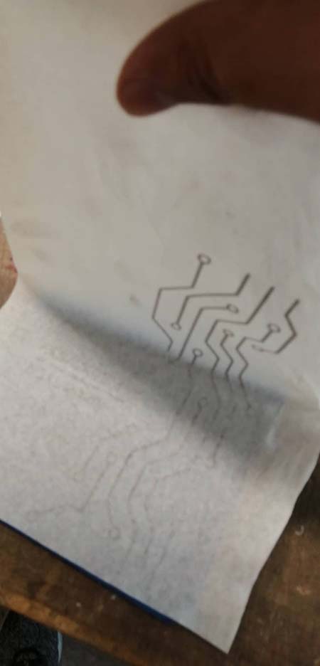
STEP 6.View final of my
Cover and
Backcover
Cover
Picture 38.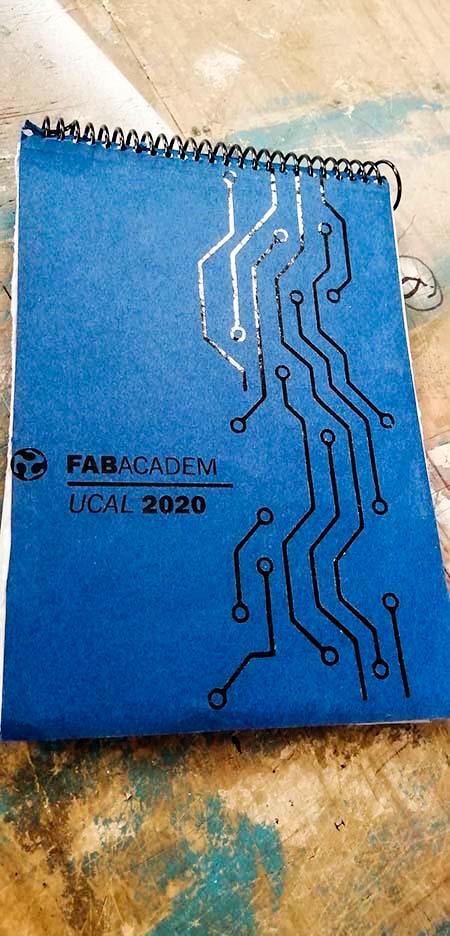 Backcover
Picture 38.1.
Backcover
Picture 38.1.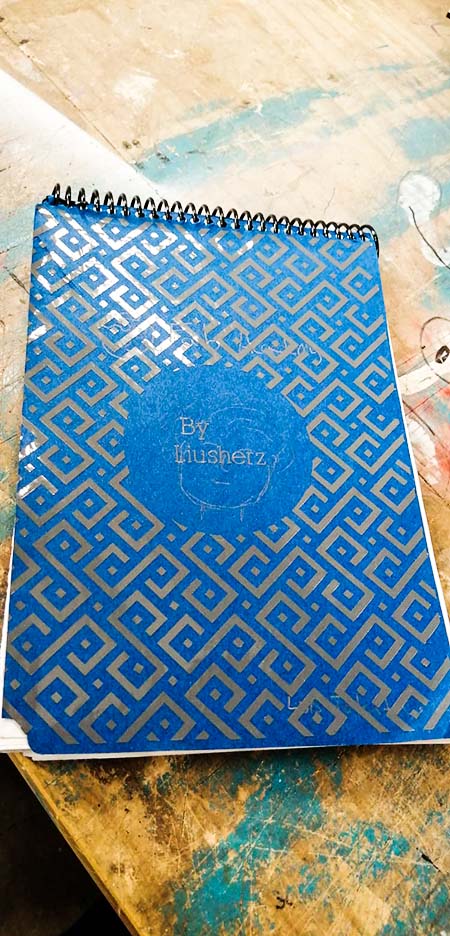
MDF Lasercut ToyGame
For this assigmetn I design three pieces a square a triangle and a octogon. with this pieces you can built enithing in you imagination. This pieces I drawed wish
Rhinoceros for do mi design. So I experiment used in lasercut project. Below are the steps.
STEP 1. Draw my idea in a paper.
Picture 39.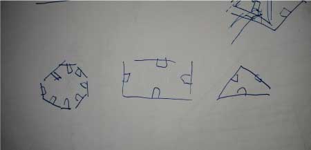
STEP 2. Draw in
Fusion 360..
Picture 40.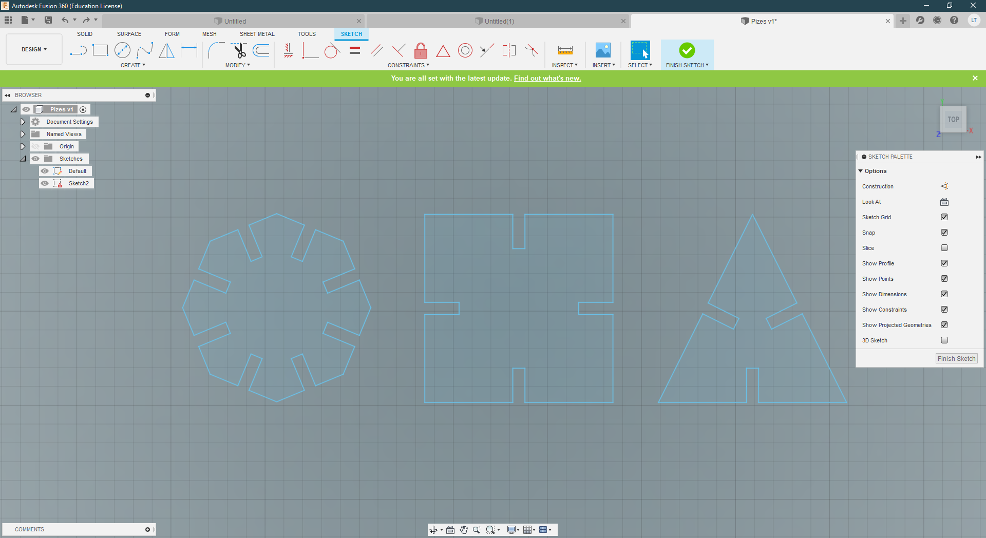 Picture 40.1.
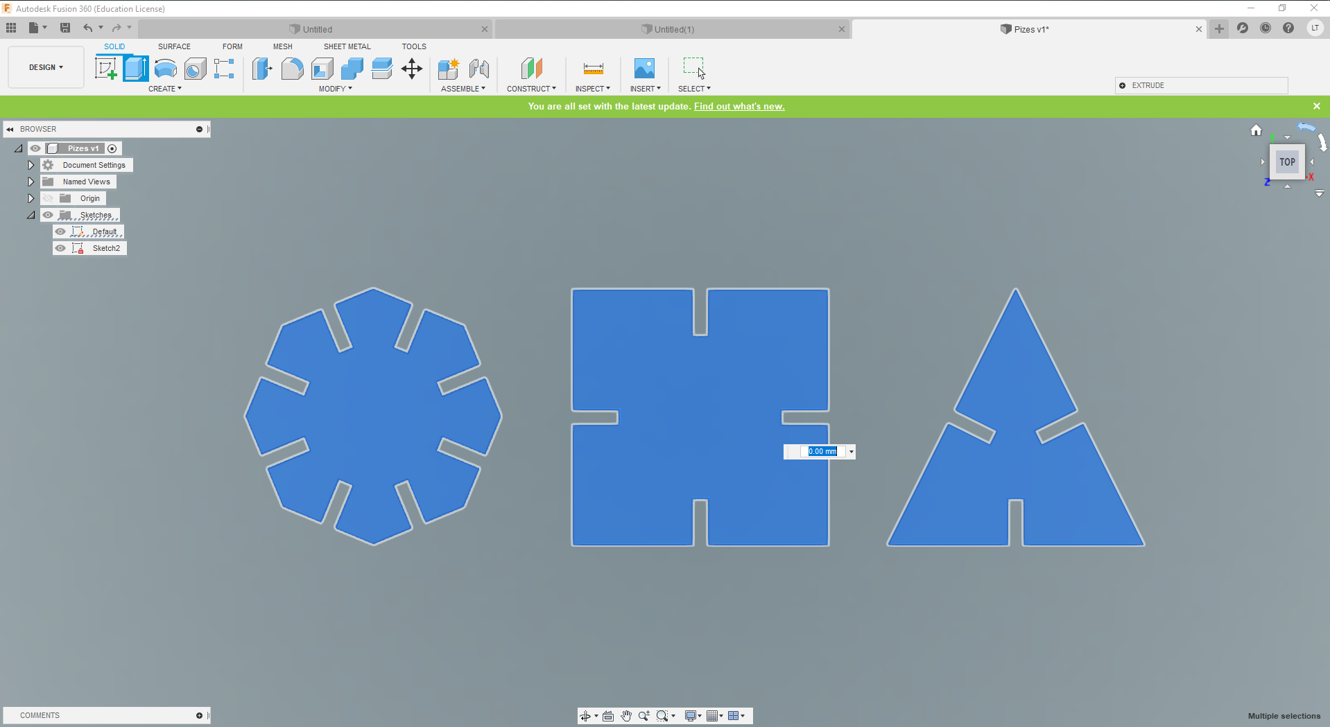
STEP 3. Next I export to Rhino to prepare my finish
Draw and put de
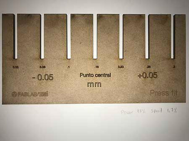
Pressfit.
Picture 41.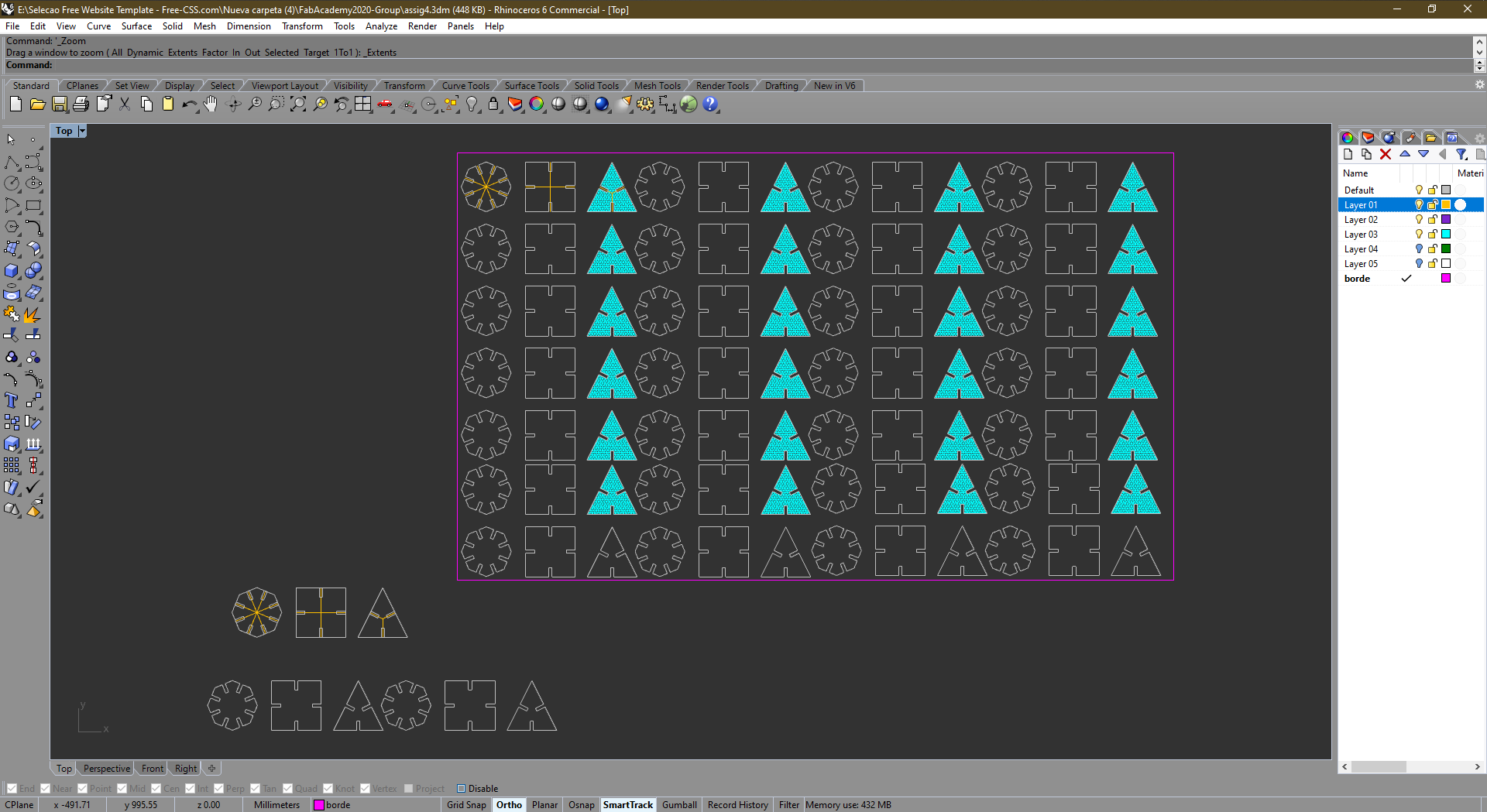
STEP 4. Upload to the
Trotec software.
Picture 42.0.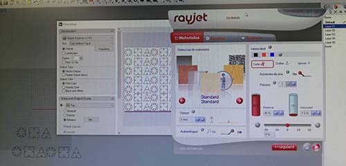 Picture 42.1.
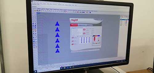
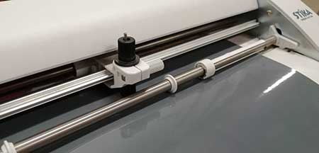
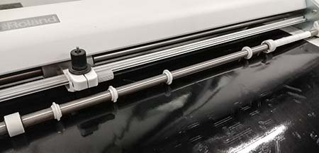
STEP 5. Calibrate and prepared the laser cutter.
Picture 43.0.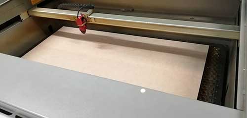 Picture 43.1.
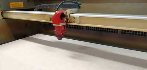
STEP 6. Take the cut.
Picture 44.0.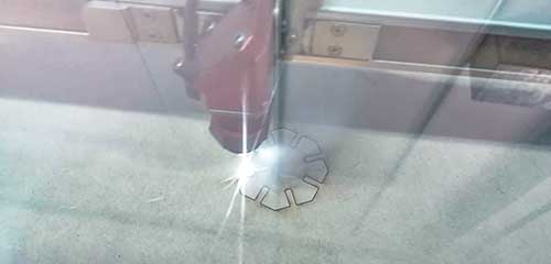 Picture 44.1.
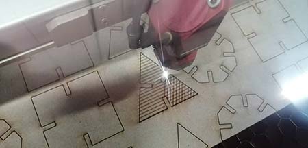 Picture 44.2.
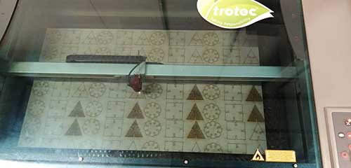 Picture 44.3.
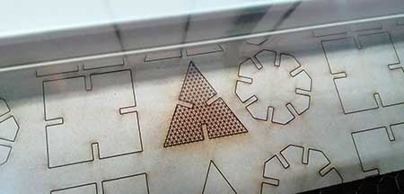
STEP 7. Ensambling and Final view.
After cutting, remove the cut pieces
(Picture 45). Then I
grouped them according to their form . After grouping them, assemble three models with the pieces. A
Tower (Picture 45.1), a
Space-Vehicle (Picture 45.2) and a
Spaceship (Picture 45.3).
Picture 45.0.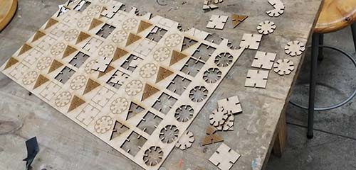 Picture 45.1.
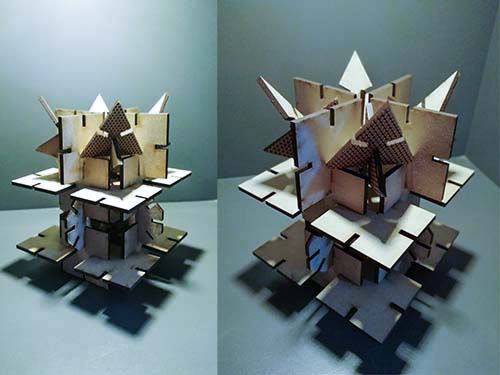 Picture 45.2.
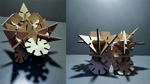 Picture 45.3.
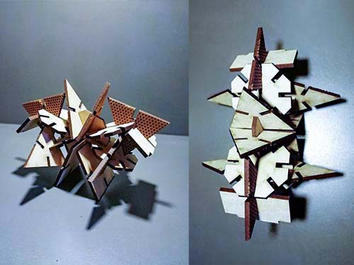
========== learned/conclusions ==========
EThis is my first assignment that I started doing within the fablab, it was extreme because we burned an mdf and also that we got stressed when doing the laser settings as we learned the first time it was a whole unknown world and but I managed to learn about markings, cuts and shading that can be done with a laser cutter. With Manuel we enjoyed cutting the boards because we saw how our meals were coming out and we enjoyed when fire came out hehehe I know it's wrong but it was fun and worth seeing!
When I cut my vinyl design it was simple and fast. The laborious and cumbersome thing was when I had to remove the material that I did not want to come out, it took me hours to get that out for this, I recommend that you do it by watching a movie or listening to good music on spotify!
=============== FILES ===============