17. Machine design & Mechanical design
Group assignment
Link for the group assignment
Files:
Here is the link for the machine files.
Individual assignment
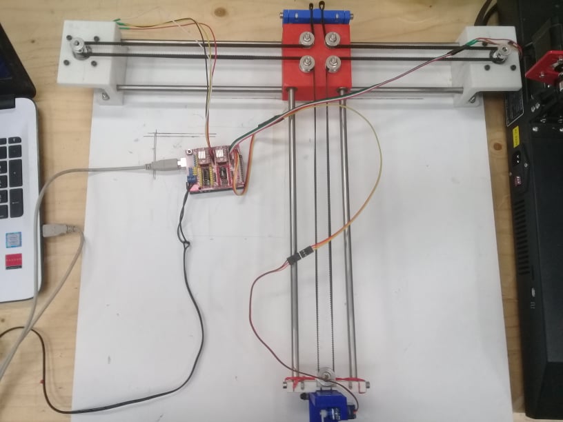
The team decided to build a CNCplotter machine.It was my idea.We started to see the different types and structures of plotter machine to finally choose and have a general idea about the components and parts to design. Our design was initially inspired from this model with a xy core.
Machine Design
At the design level, I was responsible for the design of the CoreXY mechanism which based on Axidraw machine
The mechanism is as shown here
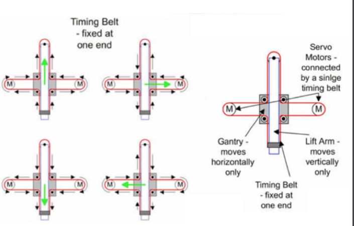
If the steppers turns in the same direction the stepper goes on X axis and if the steppers are not in the same direction the systems goes on Y axis.
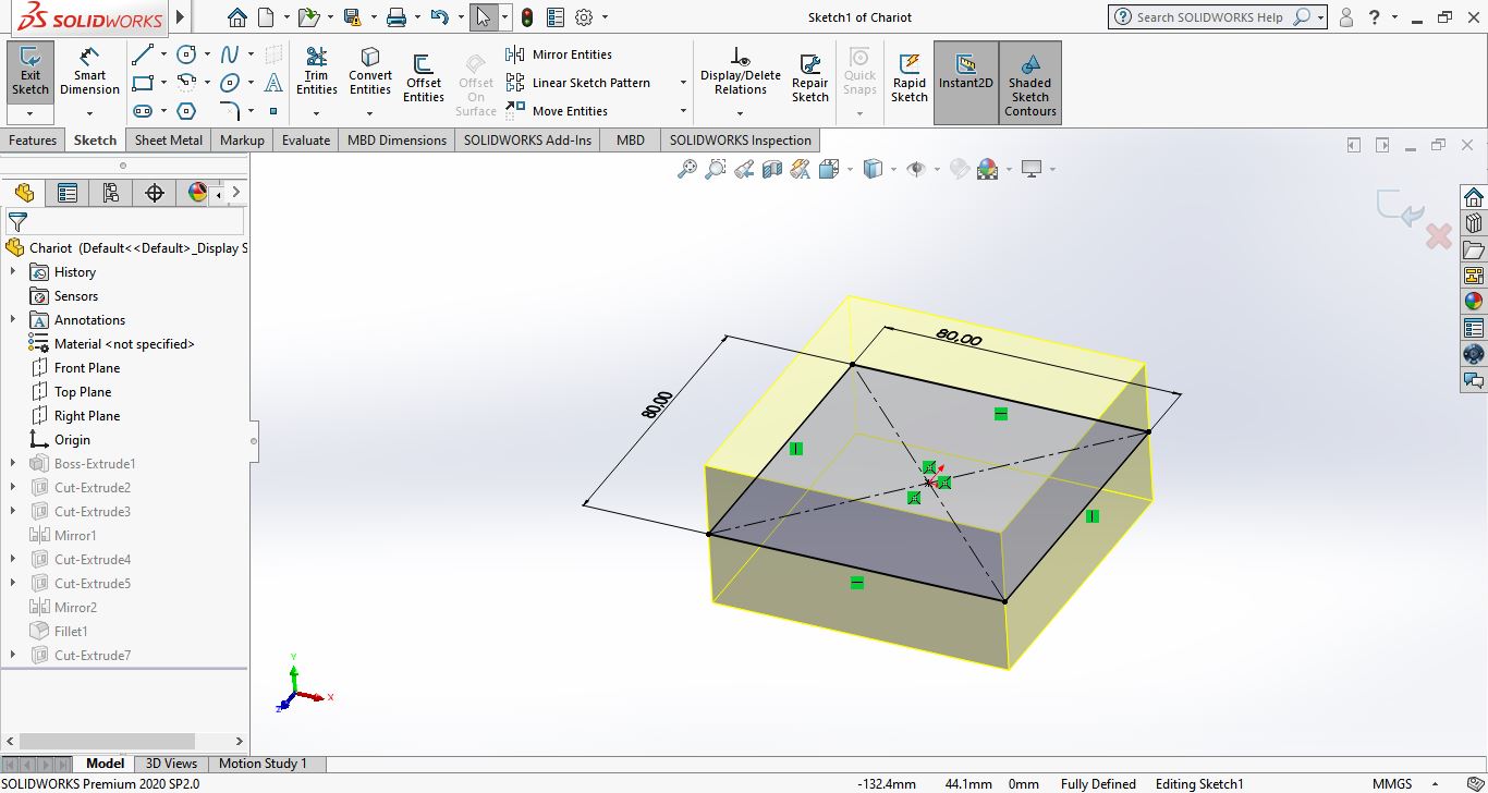
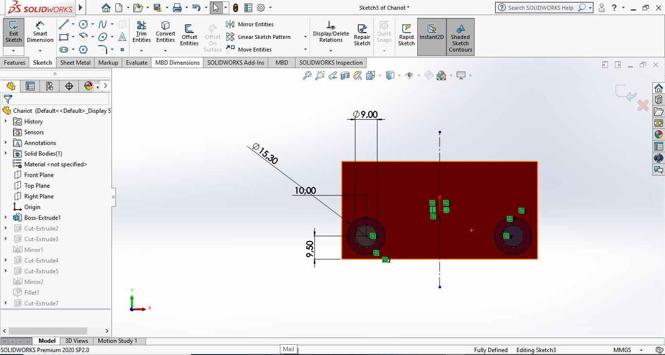
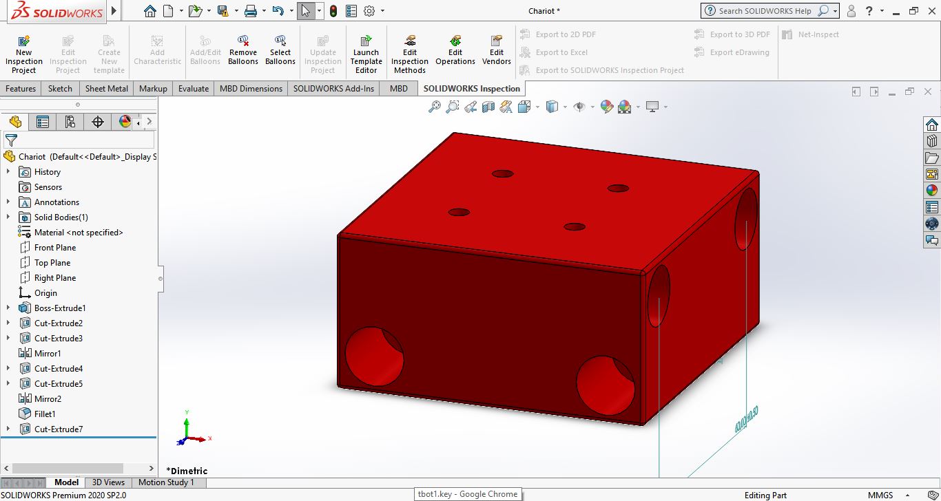
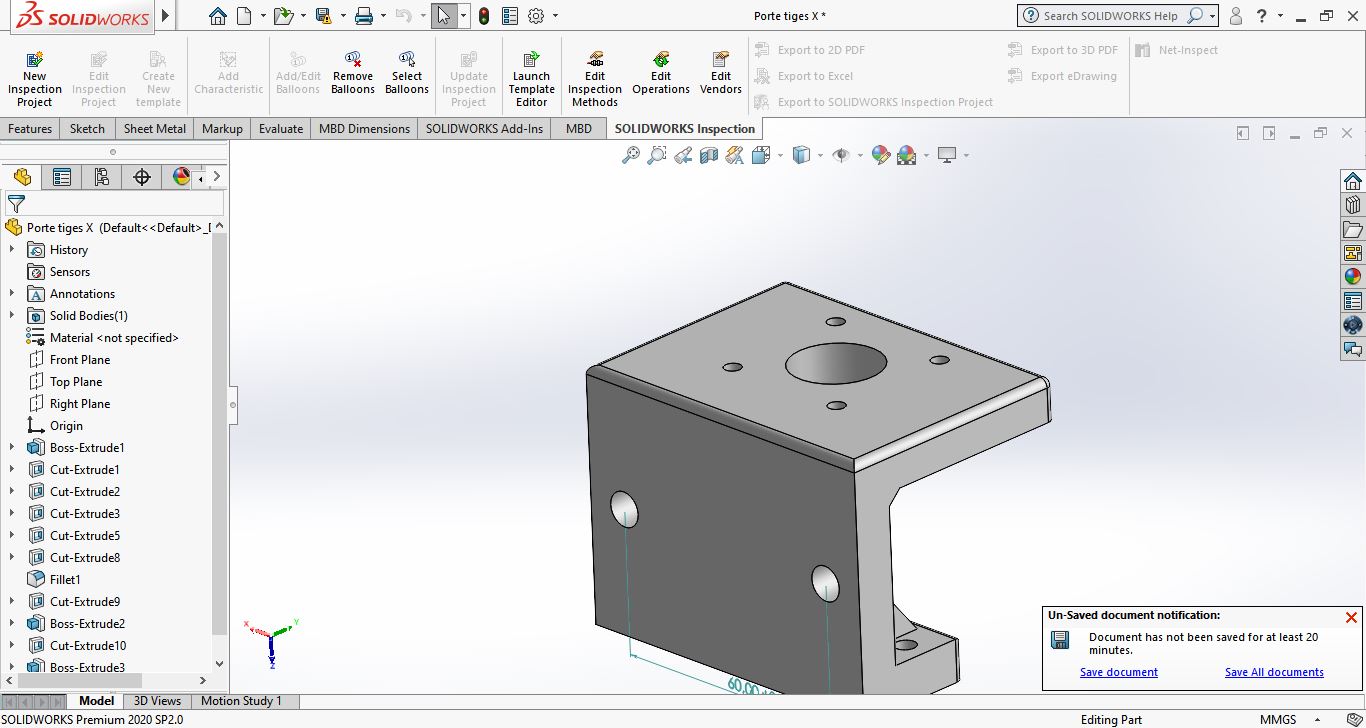
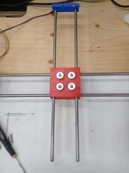
So first i designed the center part which will contain 8 LM8UU lineair bearings and 4 608 Beraingns for the timming belt.
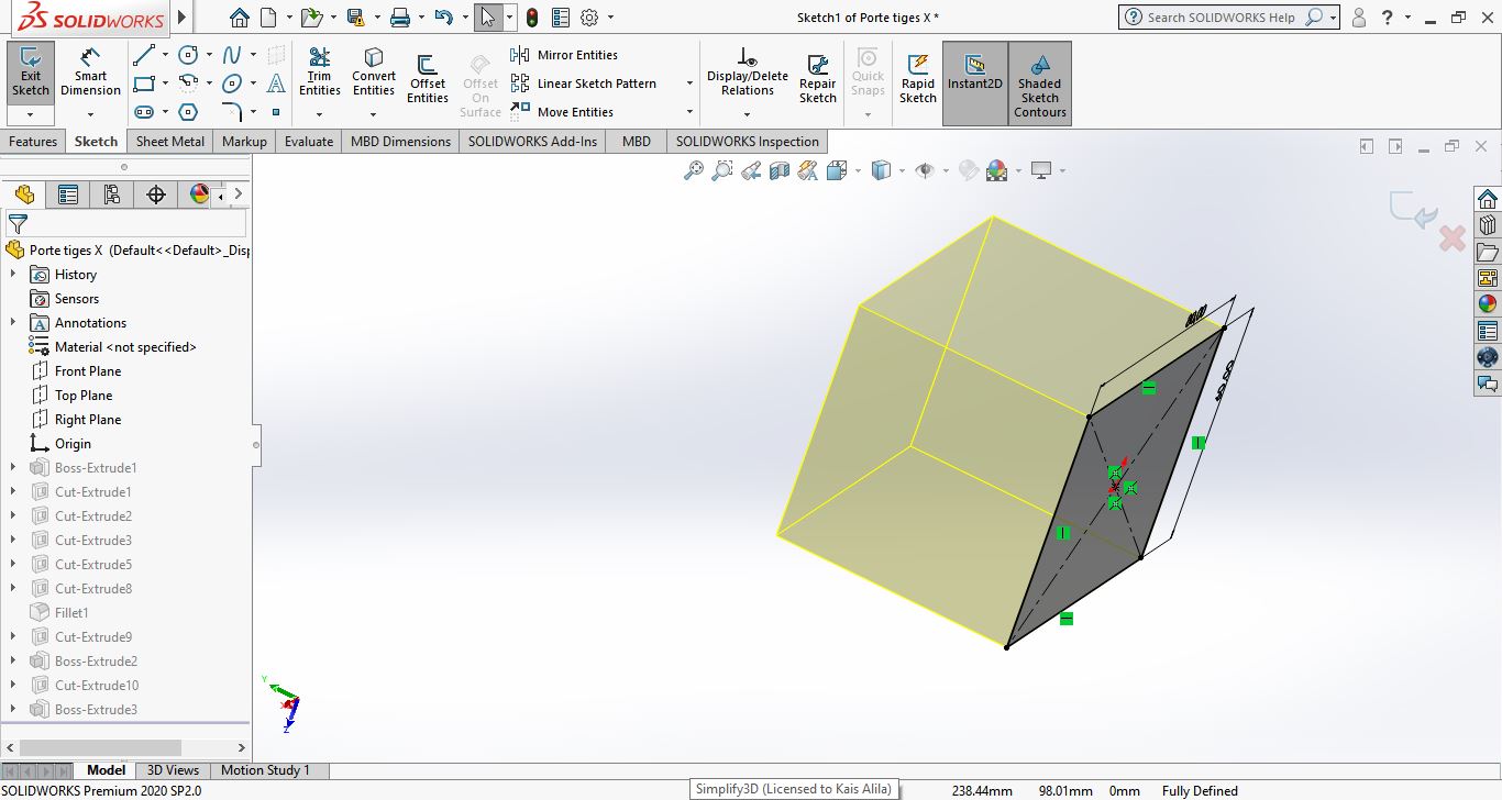
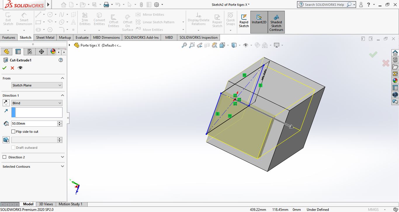
Based on the center part i modeled the two support for steppers and the lineair rods
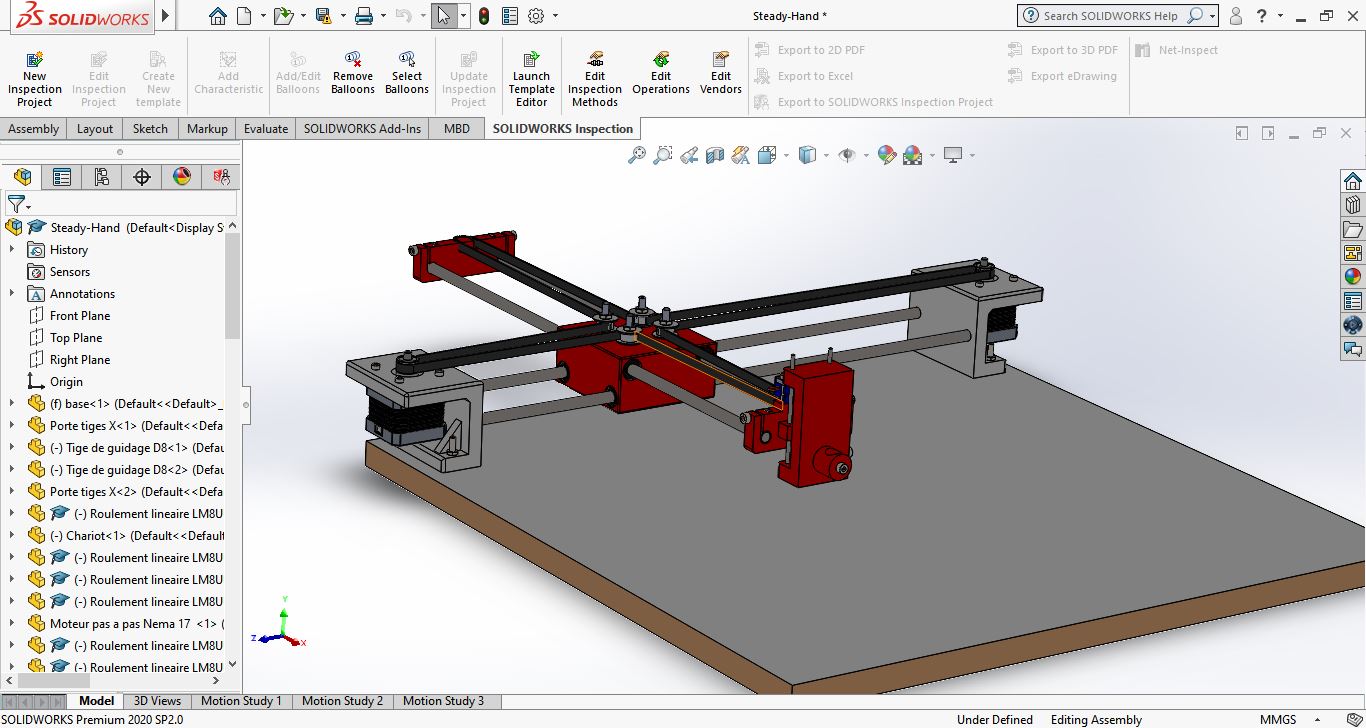
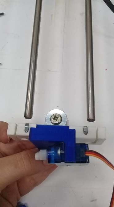
The other team member designed the other parts and I did the assembly on solidworks before that we start manufacturing. I added the steppers the servo, the bearings and the belt to the design and here how it looks
Assembly
Manufacturing
3D Printing
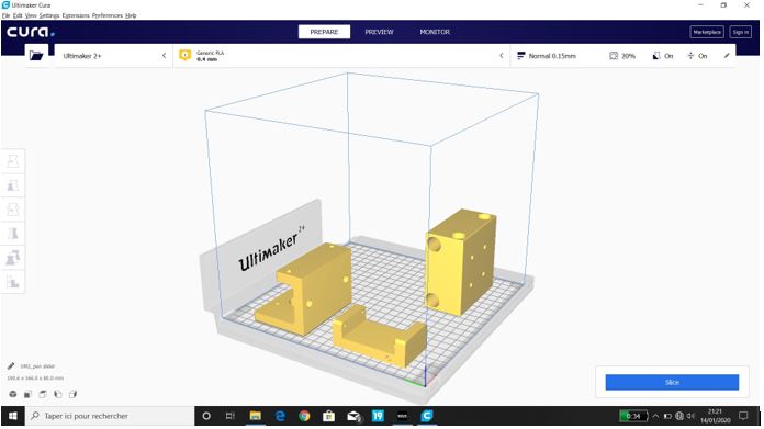
For 3D printing, I was in charge of printing some of the pieces. So I used our Ultimaker 2.
Electronics
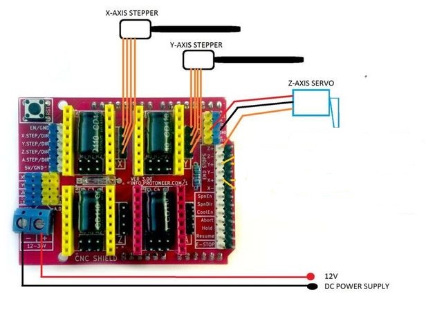
So for our machine we need an arduino Uno and a cnc shield , 2 motors and 2 A4998 drivers and a servo motor.the following figure will show the circuit to be made. Of course the CNC shield will be mounted on the Arduino.
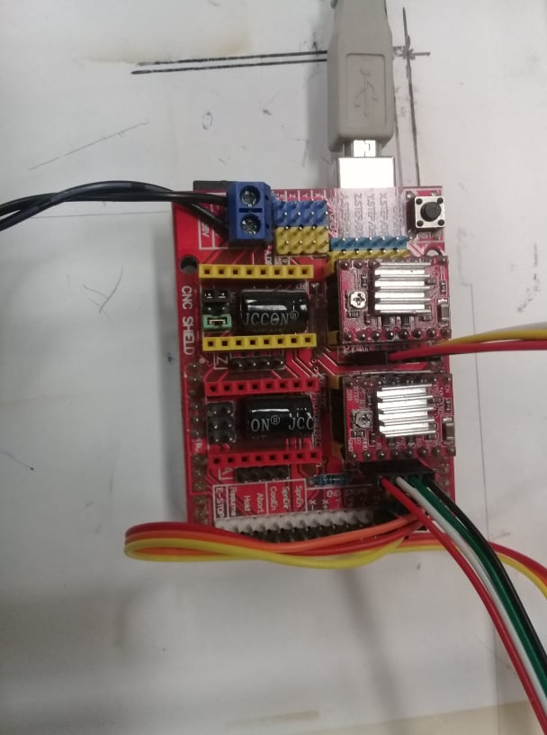
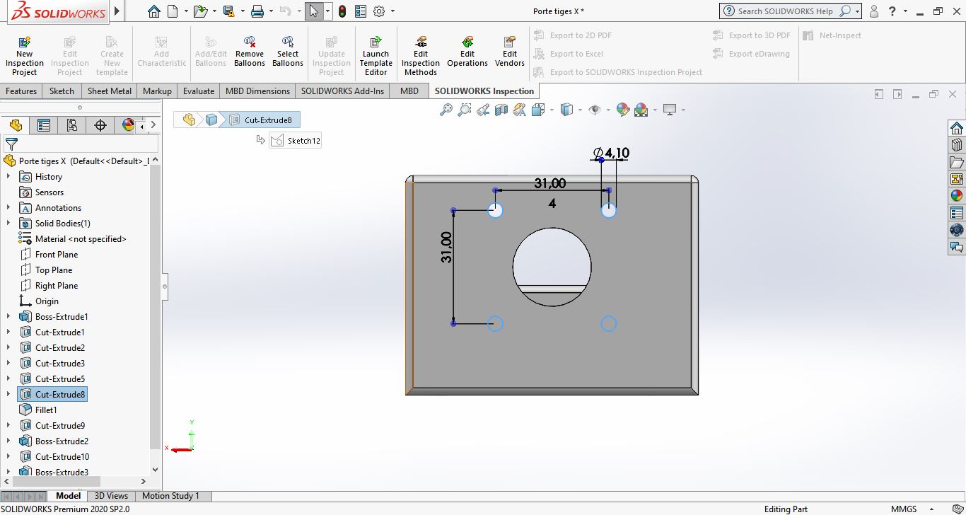
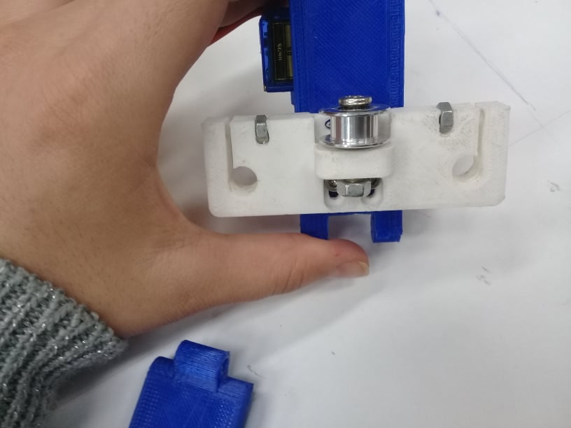
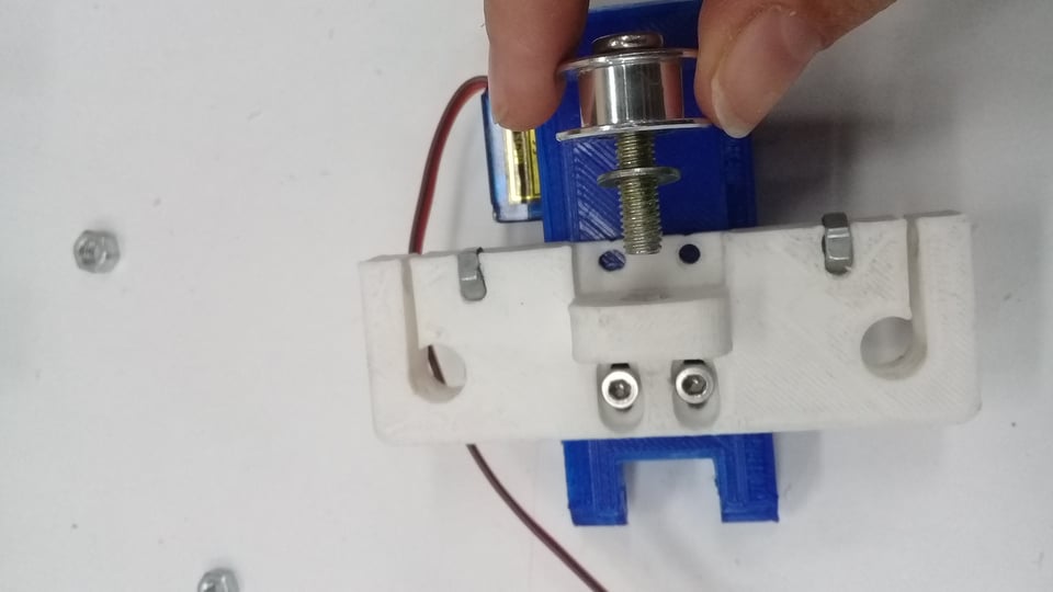
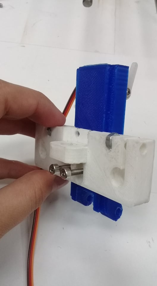
- As shown in the prvious image the part I designed is the stepper holder and at the same time the X axis rod holder which is very important one to make sure the mechanisme works correctly
Software
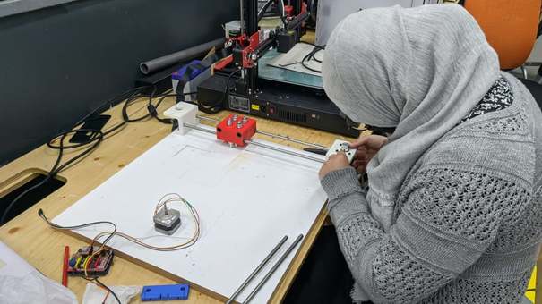
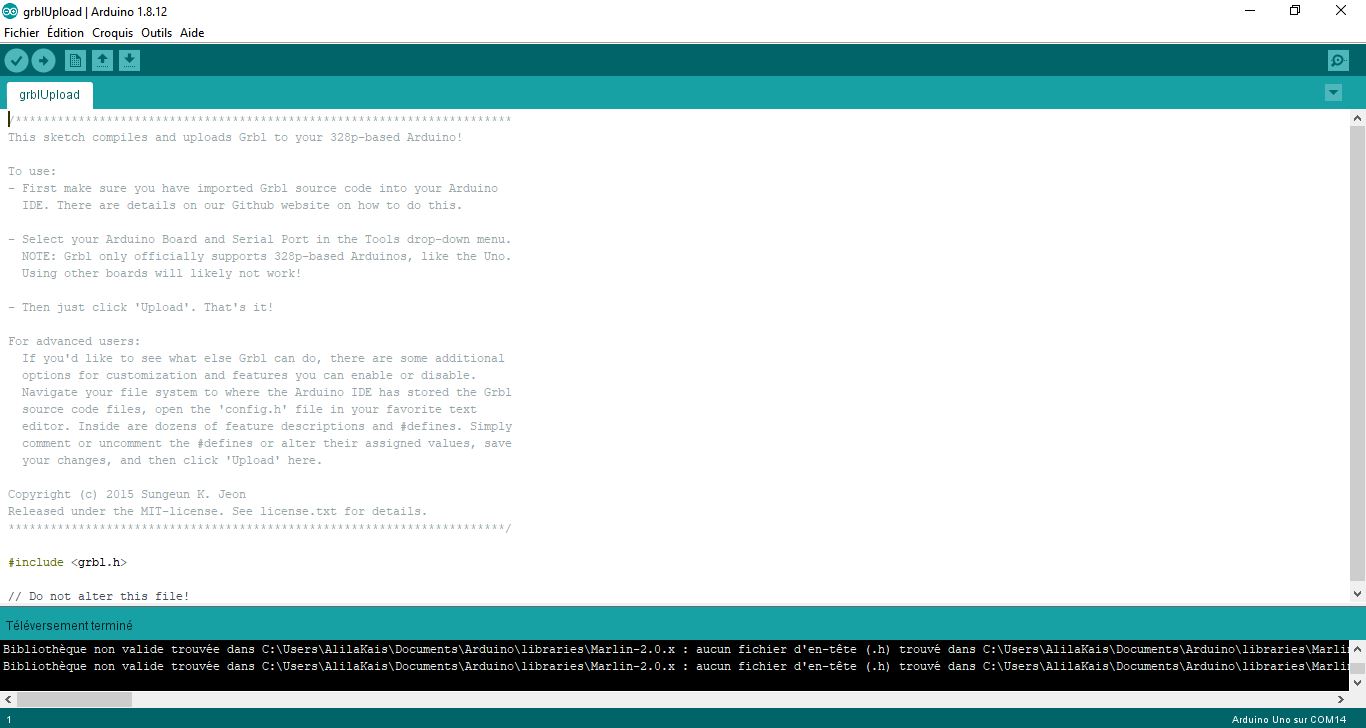
Thsi part I was responsible on is to program and configure the arduino.
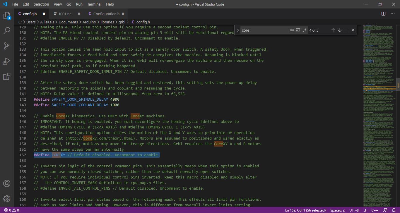
The software we used is GRBL which is a very good open source software to control CNC. For this project We used CoreXY system so the first step I ve done is to change in config.h in grbl folder
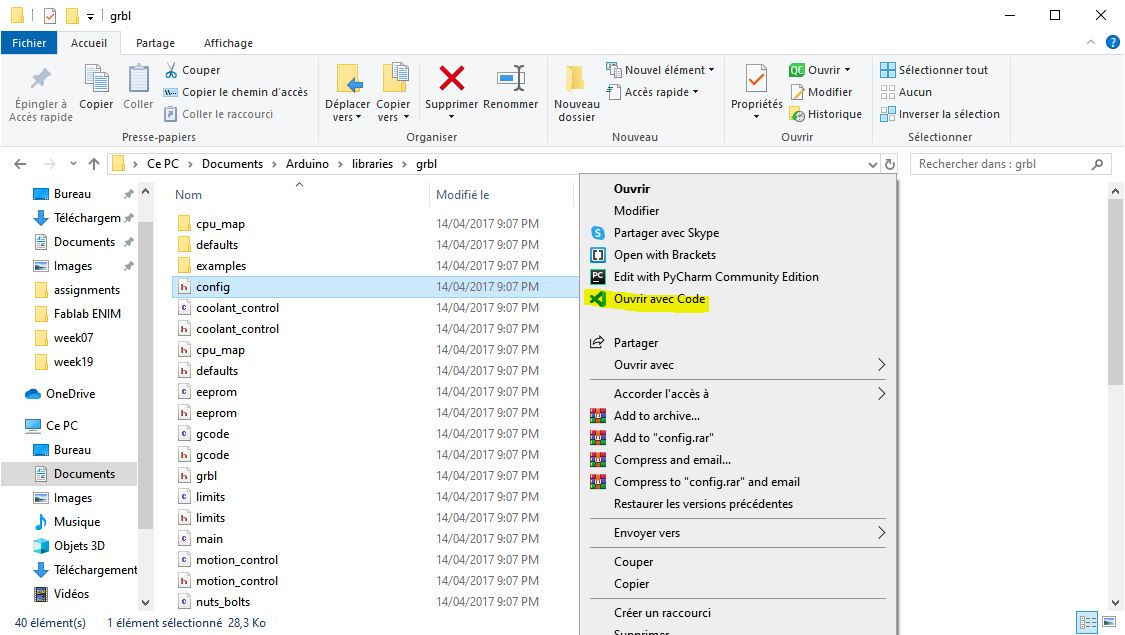
Search for #define COREXY Uncomment #define COREXY // Default disabled. Uncomment to enable.
Upload the code in the arduino
To configure GRBL you need just to follow the steps in the GRBL Wiki it was good documented in github.
We can use The serial monitor to configure GRBL or just connect the board with UGS
-
Send $$
-
Start configuering
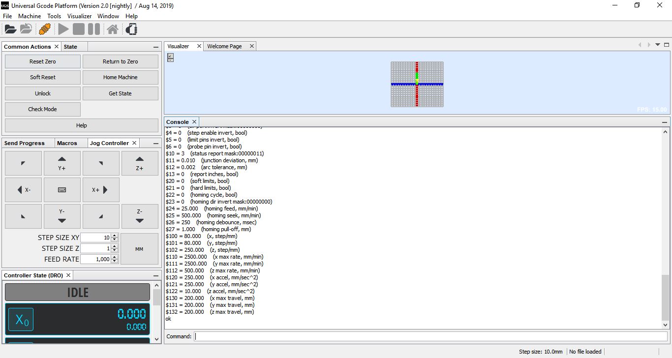
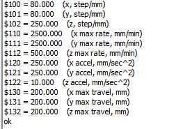
I adjusted the step per mm for X and Y axis $100=80 $101=80 beccause we are using a GT2 belt
and then I adjusted the speed and acceleration as shown in the previous image.
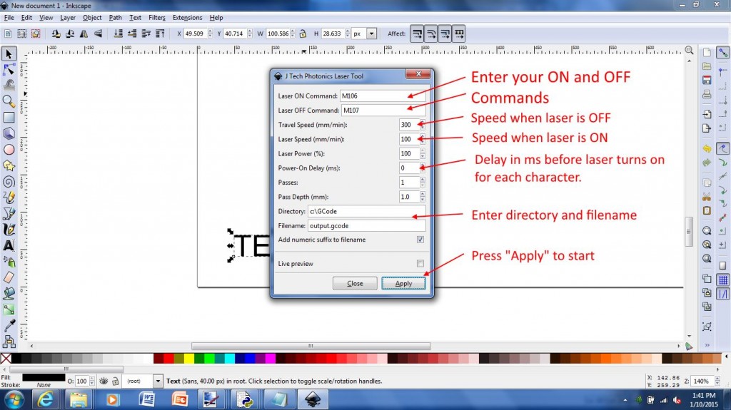
G code generation
The first test for the machine was generated using inkscape and JTP laser tool plug-in realy usefull and easy interface & the g-code generated is compatible with plotter functions.
The second software tested was LaserGRBL) which is one of the best Windows GCode streamer for DIY Laser Engraver. LaserGRBL is able to load and stream GCode path to arduino, as well engrave images, pictures and logo with internal conversion tool
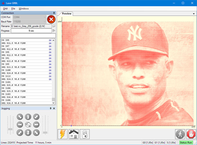
Tests
For the tests We used LaserGRBL ( you can downloaded from here)
Testing the other 2 motors
First Plot