12. Output devices
This week I worked on Stepper Motors as output device to use it after in my final project.
Group assignment
Link for the group assignment.
Stepper motors
What is a stepper motor?
A stepper motor it’s a specific kind of electrical motor which is able to turn its shaft within precise angles. It requires a dedicated driver which takes as input a simple digital on/off signal. Stepper motor are the most widely used motor in digitally controlled machines, especially the one found in a Fab Lab.
Do you know how stepper motors work?
The stepper motors use a cogged wheel and electromagnets to rotate the wheel one ‘step’ at a time.
Each HIGH pulse sent, energizes the coil, attracts the nearest teeth of the cogged wheel and drives the motor one step.
The way you pulse these coils greatly affects the behavior of the motor.
- The sequence of pulses determines the spinning direction of the motor.
- The frequency of the pulses determines the speed of the motor.
- The number of pulses determines how far the motor will turn.
Bipolar VS Unipolar Steppers
- The unipolar stepper motor operates with one winding with a center tap per phase. Each section of the winding is switched on for each direction of the magnetic field. Each winding is made relatively simple with the commutation circuit, this is done since the arrangement has a magnetic pole which can be reversed without switching the direction of the current. In most cases, given a phase, the common center tap for each winding is the following; three leads per phase and six leads for a regular two-phase stepper motor.
- With bipolar stepper motors, there is only a single winding per phase. The driving circuit needs to be more complicated to reverse the magnetic pole, this is done to reverse the current in the winding. This is done with an H-bridge arrangement, however, there are several driver chips that can be purchased to make this a more simple task. Unlike the unipolar stepper motor, the bipolar stepper motor has two leads per phase, neither of which are common. Static friction effects do happen with an H-bridge with certain drive topologies, however, this can be reduced by dithering the stepper motor signal at a higher frequency.
Bipolar motors are generally better than unipolar motors. They have more torque and are more efficient.
However, they are more complicated to drive because they need reverse current.
A4988 Pololu Drivers
What is A4988?
This driver is a carrier board for Allegro’s A4988 DMOS Microstepping Driver with Translator and Overcurrent Protection
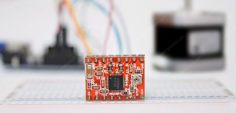
The A4988 stepper motor driver has output drive capacity of up to 35 V and ±2A and lets you control one bipolar stepper motor at up to 2A output current per coil like NEMA 17.
The driver has built-in translator for easy operation. This reduces the number of control pins to just 2, one for controlling the steps and other for controlling spinning direction.
The driver offers 5 different step resolutions viz. full-step, half-step, quarter-step, eighth-step, and sixteenth-step.
A4988 Pinout
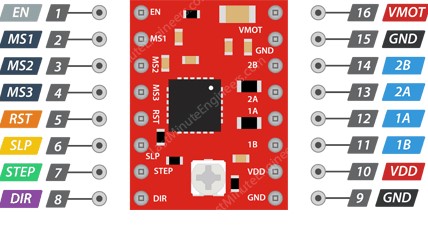
Power Connection Pins: The A4988 actually requires two power supply connections.
- VDD & GND is used for driving the internal logic circuitry which can be 3V to 5.5 V.
Whereas,
- VMOT & GND supplies power for the motor which can be 8V to 35 V.
According to datasheet, the motor supply requires appropriate decoupling capacitor close to the board, capable of sustaining 4A.
Microstep Pins:
The A4988 driver allows microstepping by allowing intermediate step locations. This is achieved by energizing the coils with intermediate current levels.
For example, if you choose to drive NEMA 17 having 1.8° or 200 steps per revolution in quarter-step mode, the motor will give 800 microsteps per revolution.
The A4988 driver has three step size(resolution) selector inputs viz. MS1, MS2 & MS3 . By setting appropriate logic levels to these pins we can set the motors to one of the five step resolutions.
| MS1 | MS2 | MS3 | Microstep Resolution |
|---|---|---|---|
| Low | Low | Low | Full step |
| High | Low | Low | Half step |
| Low | High | Low | Quarter step |
| High | High | Low | Eighth step |
| High | High | High | Sixteenth step |
These three microstep selection pins are pulled LOW by internal pull-down resistors, so if we leave them disconnected, the motor will operate in full step mode.
Control Pins:
The A4988 has two control inputs: STEP and DIR.
-
STEP input controls the mirosteps of the motor. Each HIGH pulse sent to this pin steps the motor by number of microsteps set by Microstep Selection Pins. The faster the pulses, the faster the motor will rotate.
-
DIR input controls the spinning direction of the motor. Pulling it HIGH drives the motor clockwise and pulling it LOW drives the motor counterclockwise.
Note: If you just want the motor to rotate in a single direction, you can tie DIR directly to VCC or GND accordingly.
Control Power States Pins:
The driver has three different inputs for controlling its power states viz. EN, RST, and SLP.
-
EN Pin is active low input, when pulled LOW(logic 0) the A4988 driver is enabled. By default this pin is pulled low so the driver is always enabled, unless you pull it HIGH.
-
SLP Pin is active low input. Meaning, pulling this pin LOW puts the driver in sleep mode, minimizing the power consumption. You can invoke this especially when the motor is not in use to conserve power.
-
RST is also an active low input. When pulled LOW, all STEP inputs are ignored, until you pull it HIGH. It also resets the driver by setting the internal translator to a predefined Home state. Home state is basically the initial position from where the motor starts and it’s different depending upon the microstep resolution.
Output Pins:
You can connect any bipolar stepper motor having voltages between 8V to 35 V to these pins: 1A, 1B, 2A, 2B.
Each output pin on the module can deliver up to 2A to the motor. However, the amount of current supplied to the motor depends on system’s power supply, cooling system & current limiting setting.
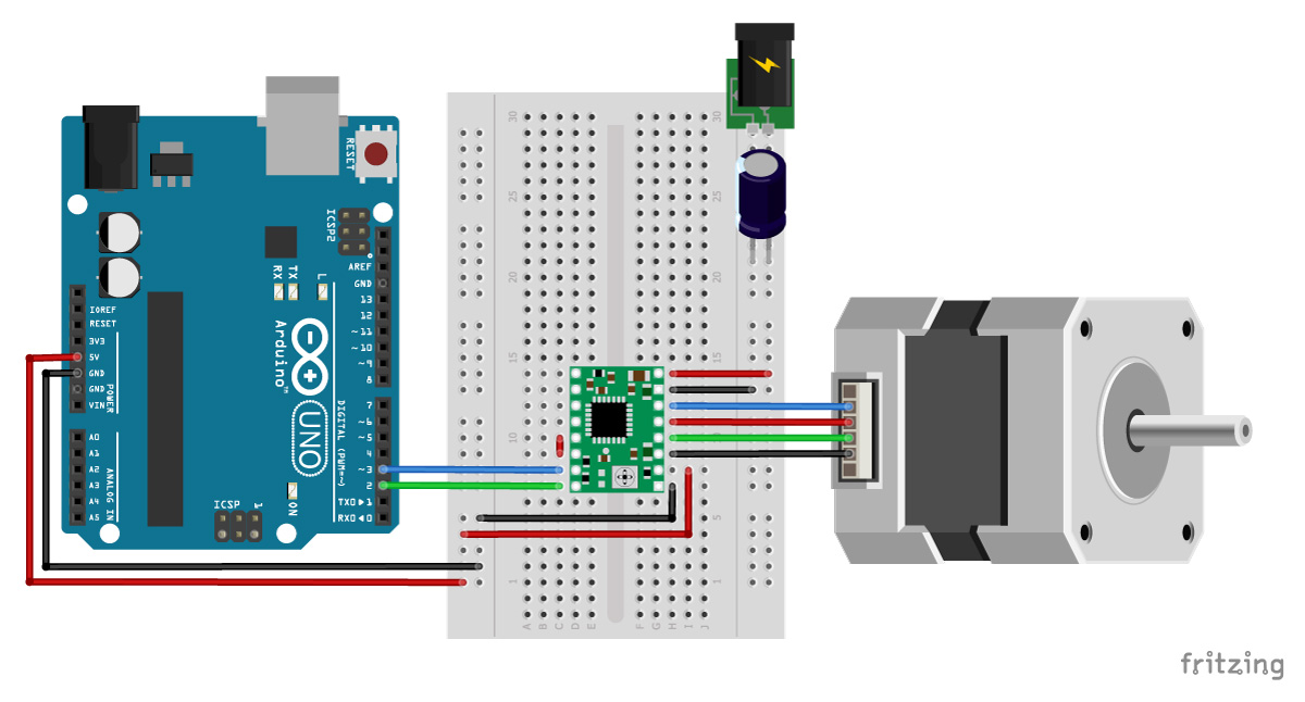
Wiring A4988 stepper driver with arduino:
Now that we know everything about the driver, we will connect it to our Arduino.
We need just: Arduino UNO, A4988 Driver , BreadBoard, Stepper Motor, Power Supply & wires.
Arduino code
The following sketch will give you complete understanding on how to control speed and spinning direction of a bipolar stepper motor with A4988 stepper motor driver.
// Define stepper motor connections and steps per revolution:
int EN = 8;
int STP = 3;
int DIR = 6;

void setup() {
  Serial.begin(9600);
  pinMode(EN,OUTPUT); //Enable
  pinMode(STP,OUTPUT); //Step
  pinMode(DIR,OUTPUT); //Dir
  digitalWrite(EN,LOW); // Set Enable Low
}

void loop() {
  digitalWrite(EN,LOW); // Set Enable Low
  digitalWrite(DIR,HIGH); // Set Dir high
  Serial.println("Loop 200 steps (1 rev)");
  for (int x = 0 ; x < 5 * 200; x++)// Loop 200 times
  {
    digitalWrite(STP,HIGH); //Output High
    delay(1); //wait
    digitalWrite(STP,LOW); //Output High
    delay(1); //wait
  }
  Serial.println("pause");
  delay(1000); //Pause 1s
}
The sketch starts with defining the step, direction & Enable pins. I connected them to Arduino pin 3, 6 & 8.
int EN = 8;
int STP = 3;
int DIR = 6;
In setup section of code, all the motor control pins are declared as digital OUTPUT.
Serial.begin(9600);
  pinMode(EN,OUTPUT); //Enable
  pinMode(STP,OUTPUT); //Step
  pinMode(DIR,OUTPUT); //Dir
  digitalWrite(EN,LOW); // Set Enable Low
In loop section we spin the motor clockwise slowly and then spin it counterclockwise quickly at an interval of a second.
Control Spinning Direction: To control the spinning direction of a motor we set the DIR pin either HIGH or LOW. A HIGH input spins the motor clockwise and a LOW will spin it counterclockwis
 digitalWrite(EN,LOW); // Set Enable Low
  digitalWrite(DIR,HIGH); // Set Dir high
  Serial.println("Loop 200 steps (1 rev)");
  for (int x = 0 ; x < 5 * 200; x++)// Loop 200 times
  {
    digitalWrite(STP,HIGH); //Output High
    delay(1); //wait
    digitalWrite(STP,LOW); //Output High
    delay(1); //wait
  }
  Serial.println("pause");
  delay(1000); //Pause 1s
Control Speed: The speed of a motor is determined by the frequency of the pulses we send to the STEP pin. The higher the pulses, the faster the motor runs. A pulses is nothing but pulling the output HIGH, waiting a bit then pulling it LOW and waiting again. By changing the delay between two pulses, you change the frequency of those pulses and hence the speed of a motor.
Download Files: Arduino file
Video
My Board
This week, I designed my board to controll nema 17 stepper based on Attiny44 and A4988 Pololu driver.
Design the board
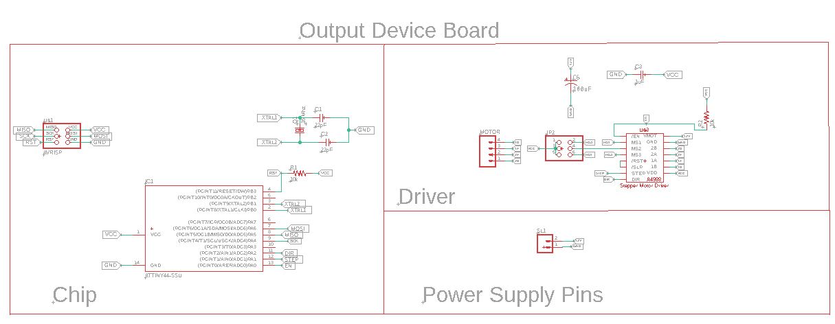
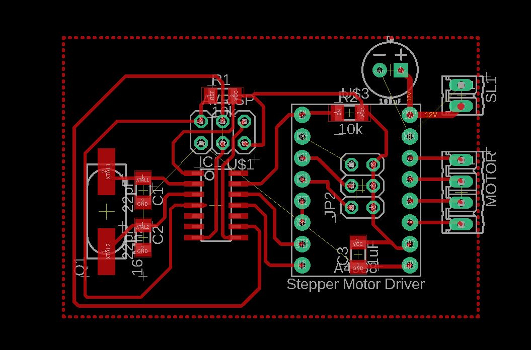
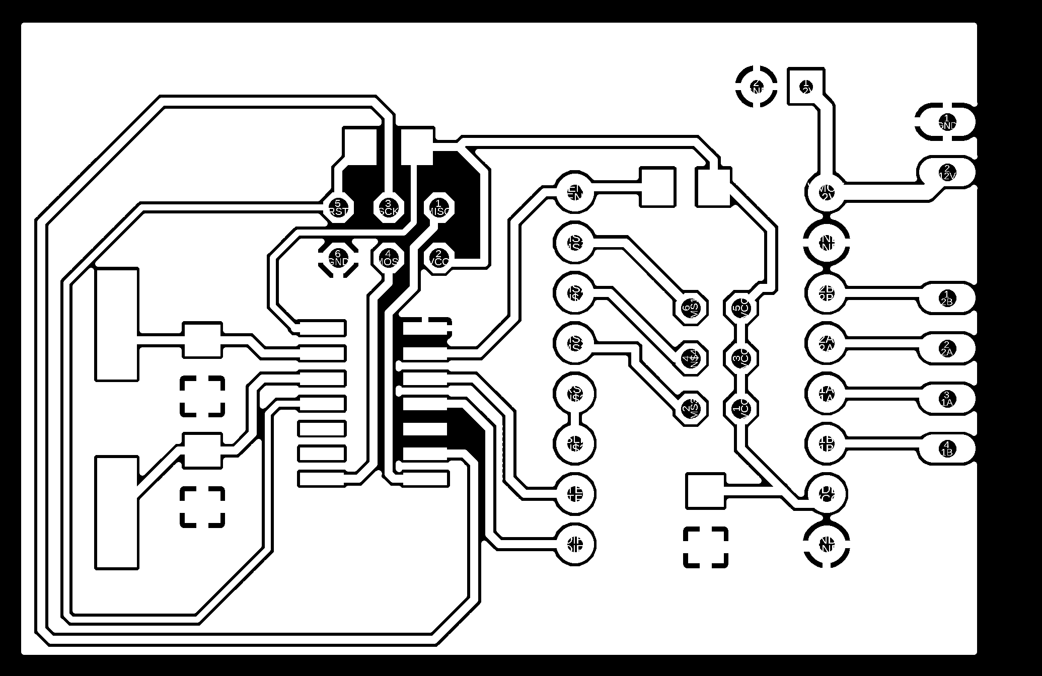
Components: * x1 ATTINY44-SSU * x2 22pF Capacitor 1206 * x1 1uF Capacitor 1206 * x1 100uF Capacitor 1206 * x1 16 Mhz CRYSTAL * x2 10k resistors 1206 * x1 M02 pin connector * x1 M04 pin connector * x2 2x3 PinHeasd (for the driver and for the AVRISP) * x2 2x3 PinHeasd (for the driver and for the AVRISP) * x1 A4988 driver
Download Files: Board file