4. Computer controlled cutting
Group Assignment
Here is the link for the groupe assignment page
Laser cutter: Setup and Test
Make test part(s) that vray cutting and dimensions, to characterize our laser cutter.
Hardware
-
Setup:
-
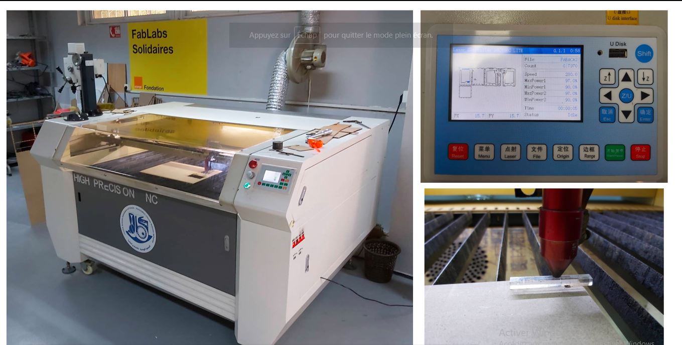
Tool: Laser cutter CO2
-
Class: 3R (for this class, lasers are considered safe when handled carefully. There is only a small hazard potential for accidental exposure. For visible-light lasers, Class 3R lasers’ output power is between 1 and 4.99 milliwatts.
-
Laser Power: 100 watt.
-
Model: Golden Sign GS9070
-
Materials: Plywood/Mdf 4mm; Cardboard 6mm; Plexigrass 5mm
1- Switch ON the laser
2- Switch ON the pointer
3- Unlock X/Y motor axes
4- helping you with the pointer, move the X/Y axes to set the user origin, in the upper left corner of the piece to cut, then SET with Origin Button
5- Set the Focus helping yourself with the spacer tool, unscrew the laser head screw, move the laser head Up or down, until the spacer touches the surface of the piece to be cut.
Software
Before using the machine, We started designing our own Test Template using Fusion 360 in 2D sketching.
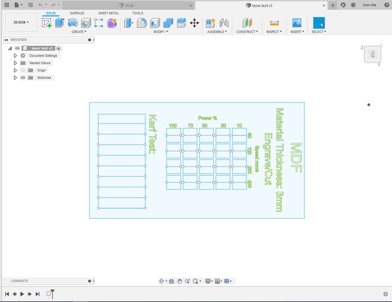
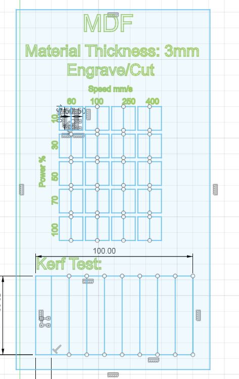
We took inspiration from other open source laser test templates and we made our own template after, we chose to test cutting and engraving at the same time on MDF 3mm with diffrent speed and laser power for each rectangle test (like shown in the previous image). Then export the sketch to DXf format.
Download File: Template DXF; Template AI
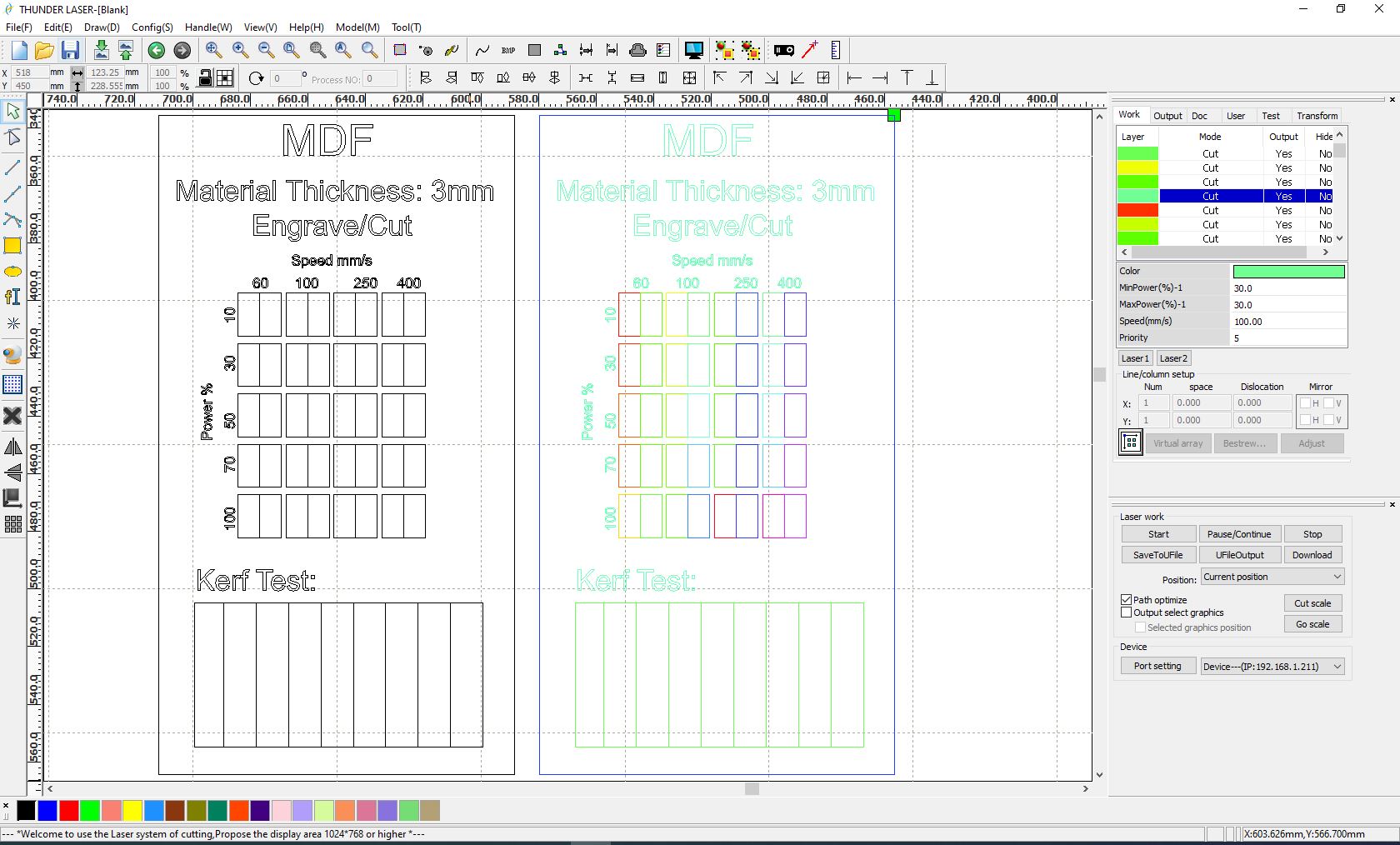
we usually use RDworks or LaserCAD to manage and send the job to the laser. The software can set parameters (setting) like power, speed and frequency per color or for the whole job, but only lines thinner than a dpi-dependent threshold are recognized to be cut. Since our template required so many different settings, we had to use multiple colored layers to stack all the power settings. RDworks has a limited number of layers and so it became very time consuming to cut even one template. (Import dxf file to the software)
this is the final result of the group assignment:
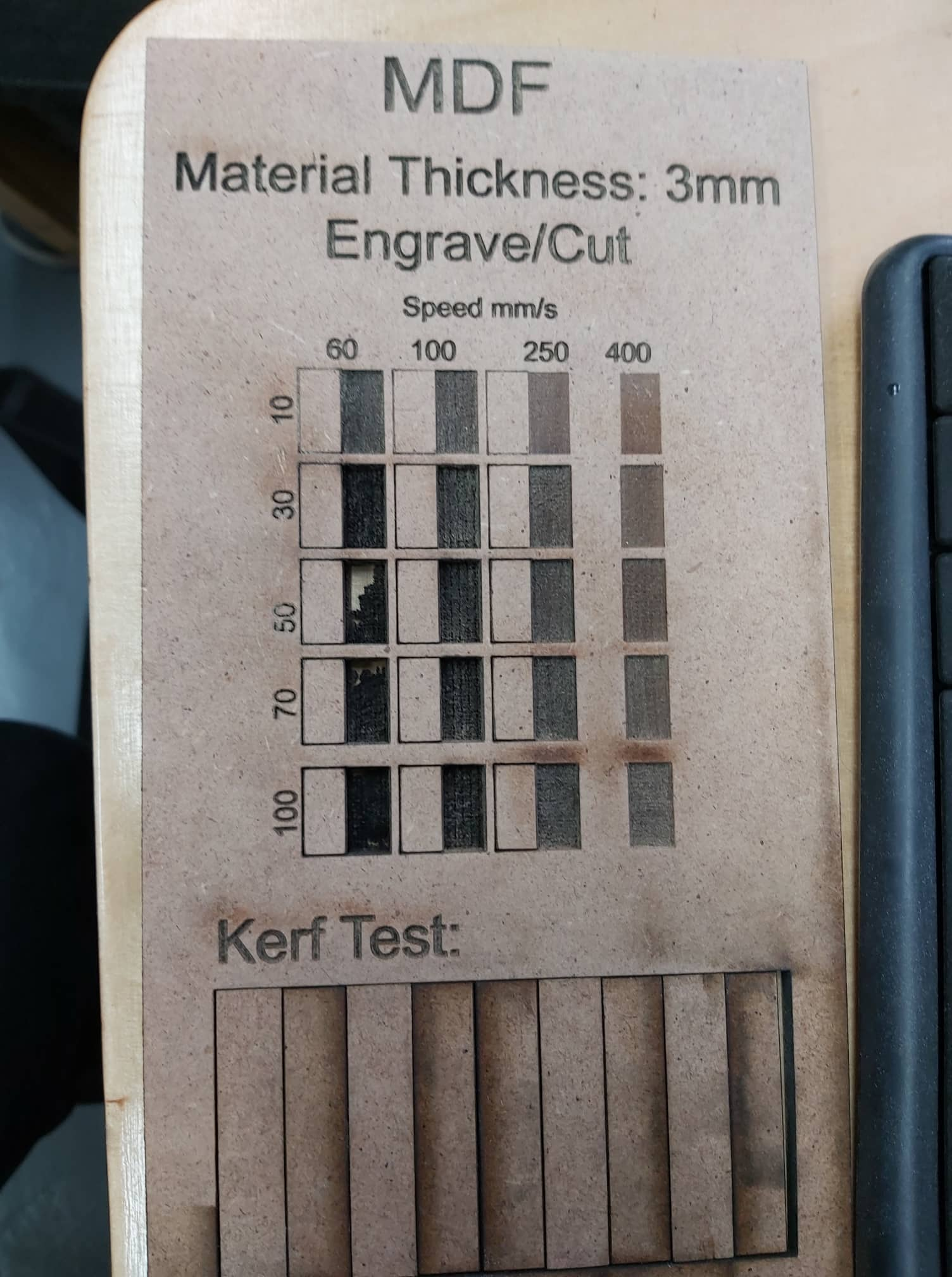
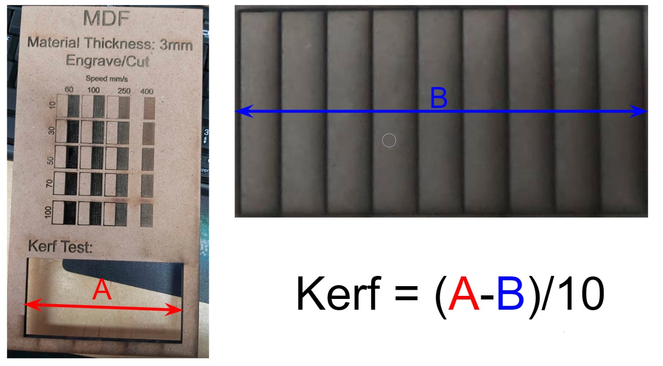
- Kerf:
We did also a Kerf test: Kerf is determined by material properties and thickness, the focal length of the lens and the gas used while cutting, I’ve designed a simple test in order to find a kerf. As in the previous picture we have drawn 9 rectangular pieces (10mm each) for 10 vertical cuts. This for make an average on the long distance.
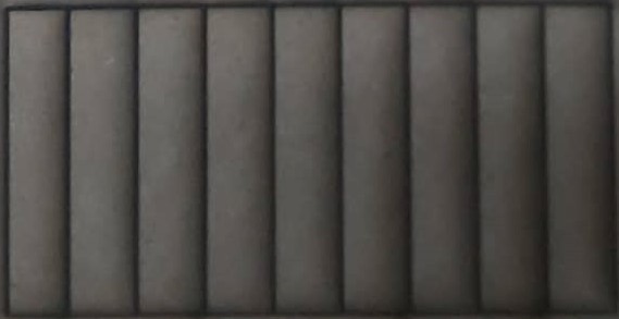
Dividing this gap by ten gives the average kerf for that material and material thickness. In the our case we’ve obtained a 0.3mm kerf for plywood with 3mm thickness.
Individual assignments
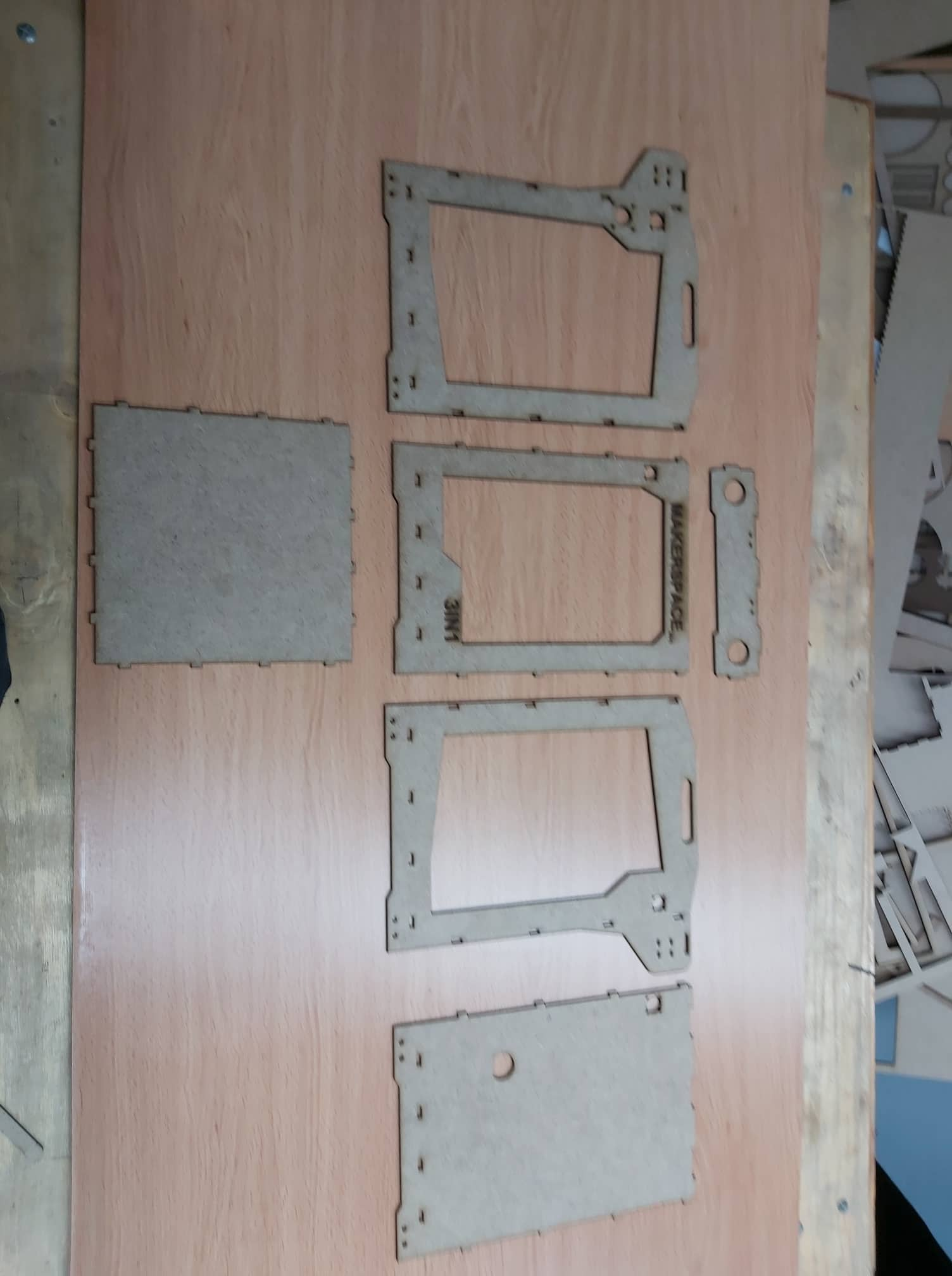
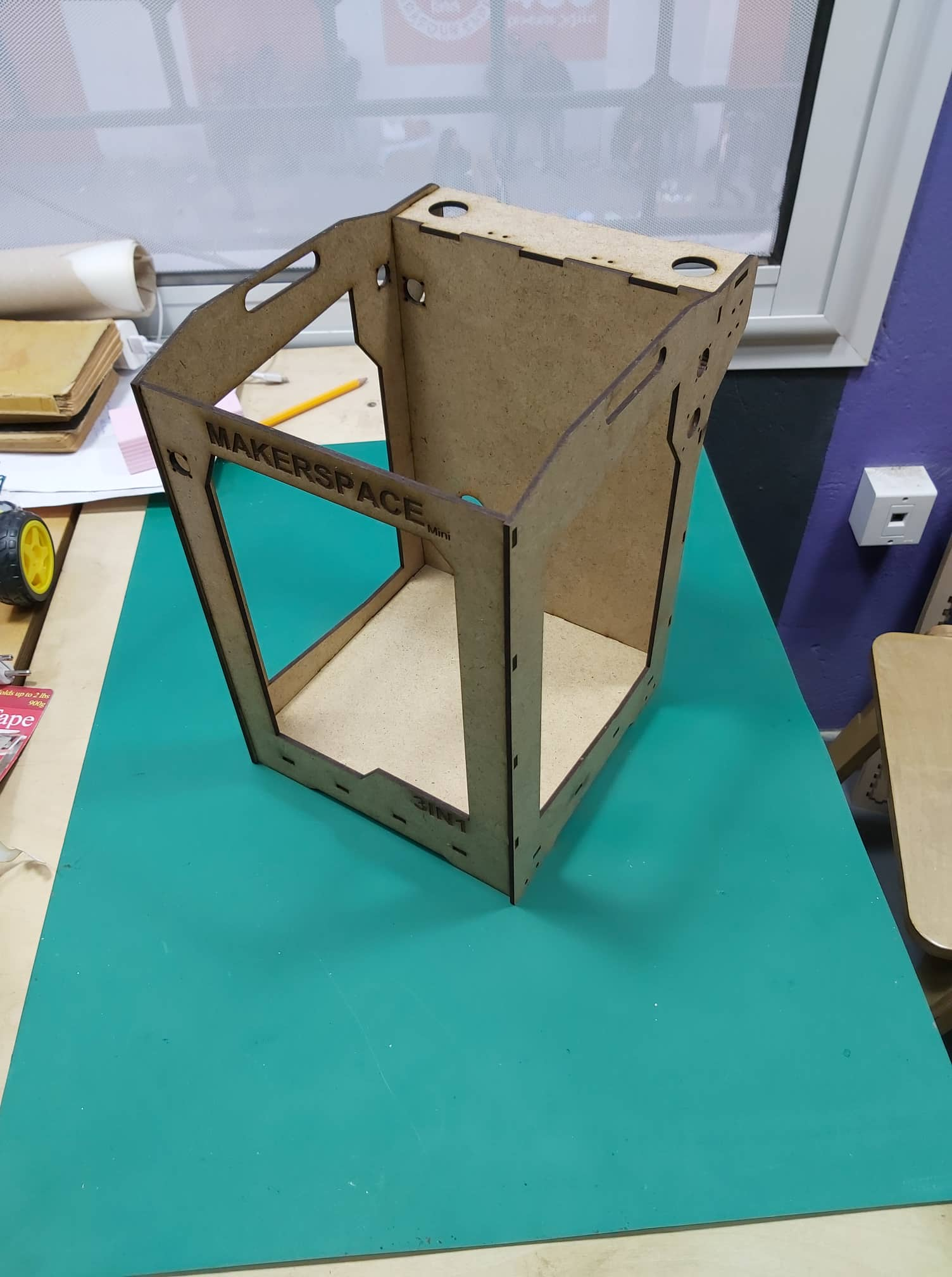
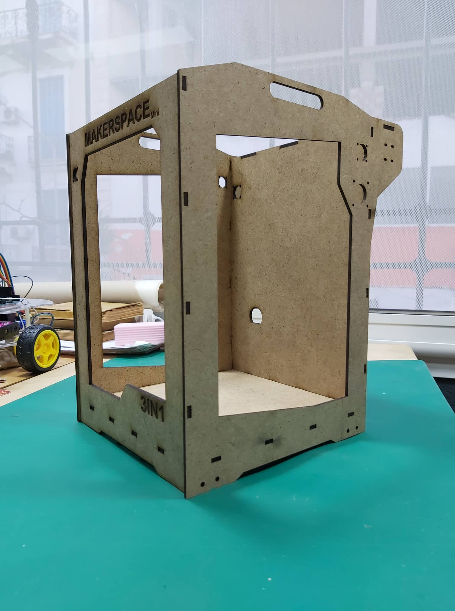
I decided to make a small mock-up of the machine, so I used the frame like a parametric press-fit construction kit.
- Fusion 360:
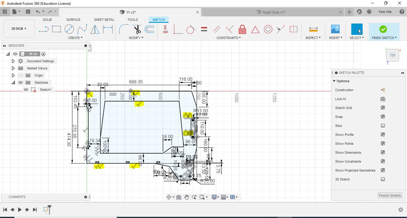
I used Fusion 360 in parametric design, the frame of the machine was designed to be assembled like puzzle so I added some parameters on the frame. The first step was to add parameters:
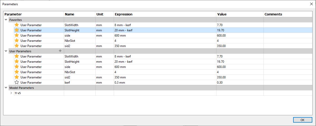
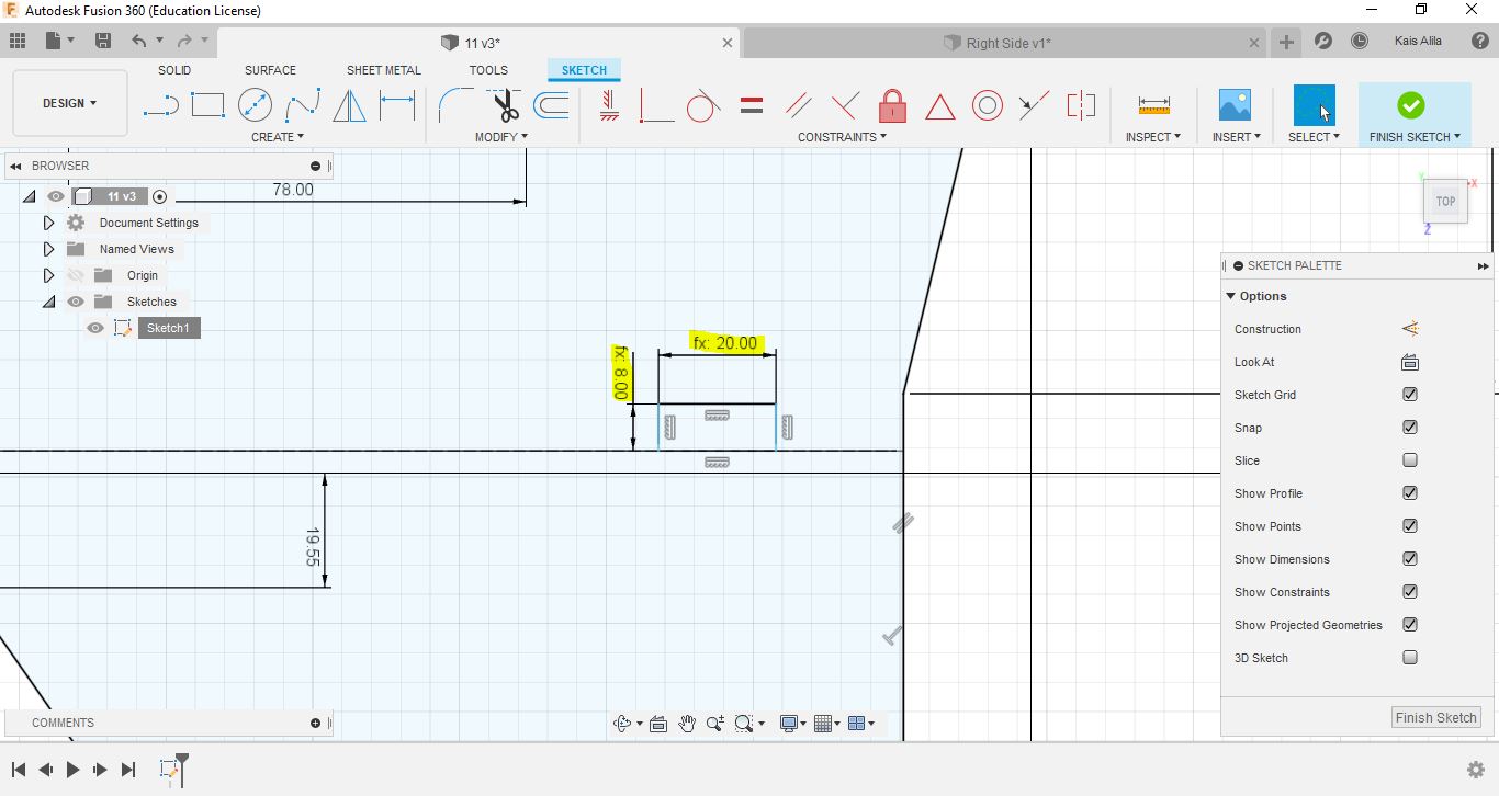
The sign “(fx:)” will appear, this means that you can modify the model after without editing the sketch.
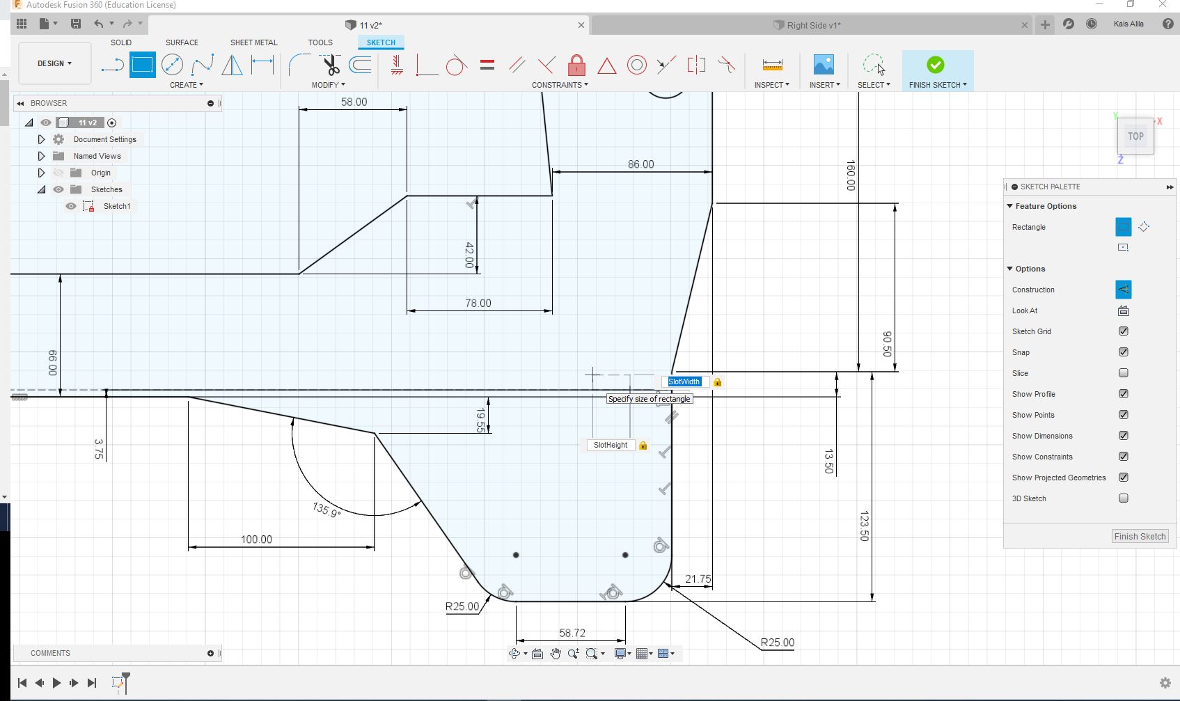
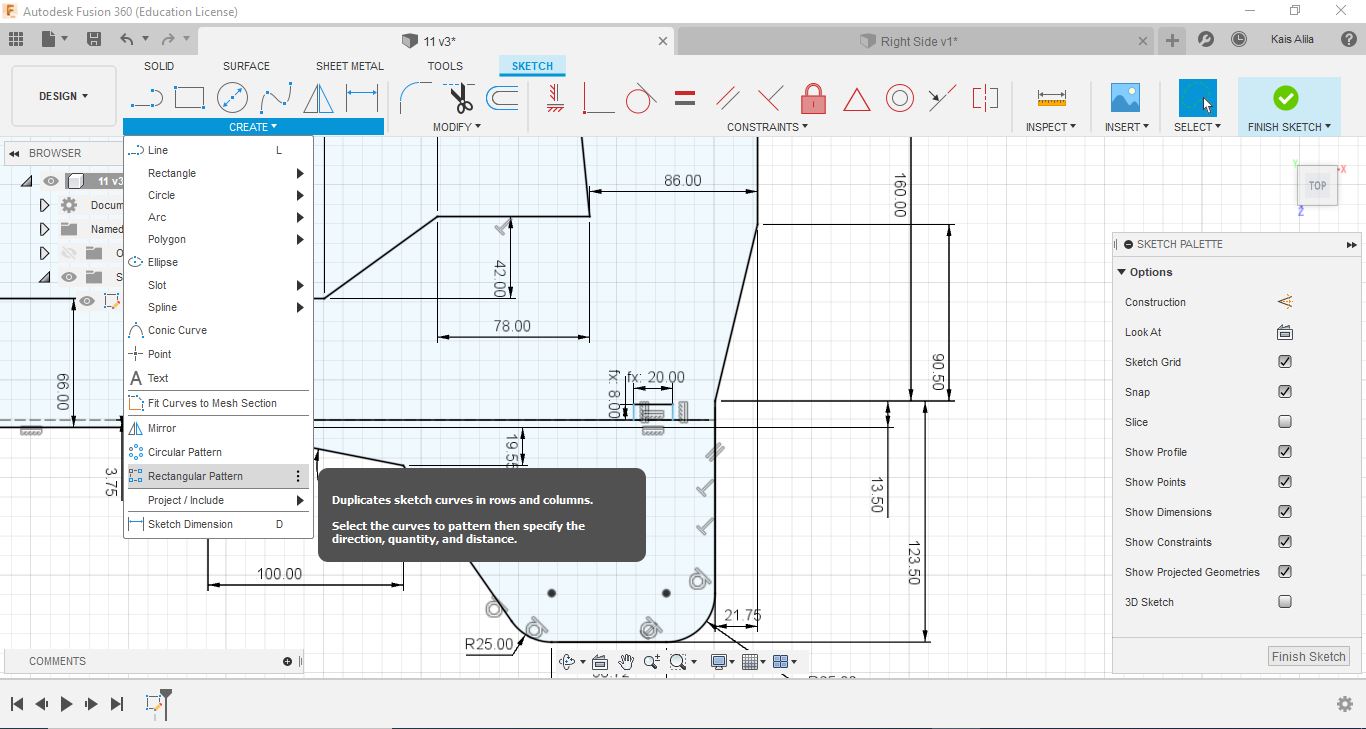
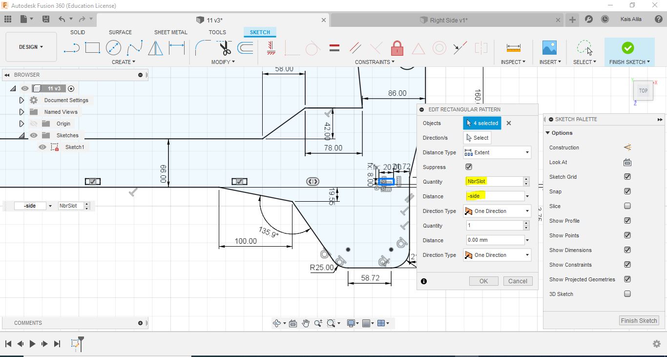
To make the slots faster I used Rectangular pattern tool
and thats the final result.
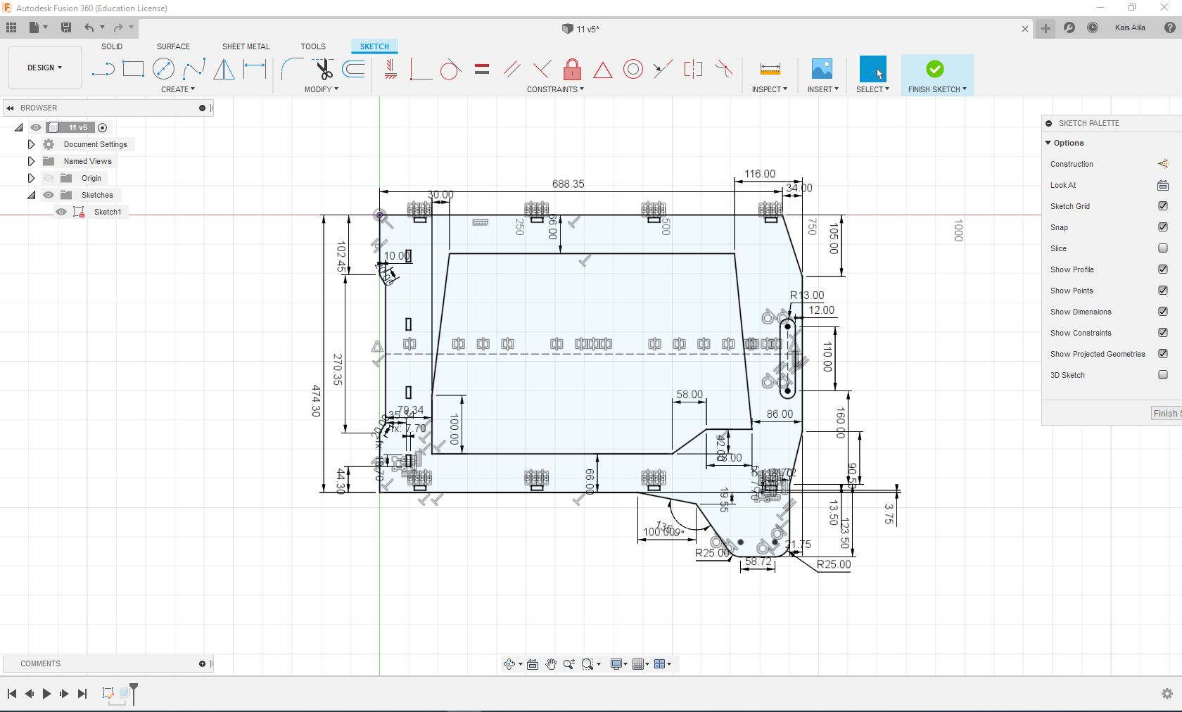
I did the same steps for the rest part of the frame then exporting to DXF format.
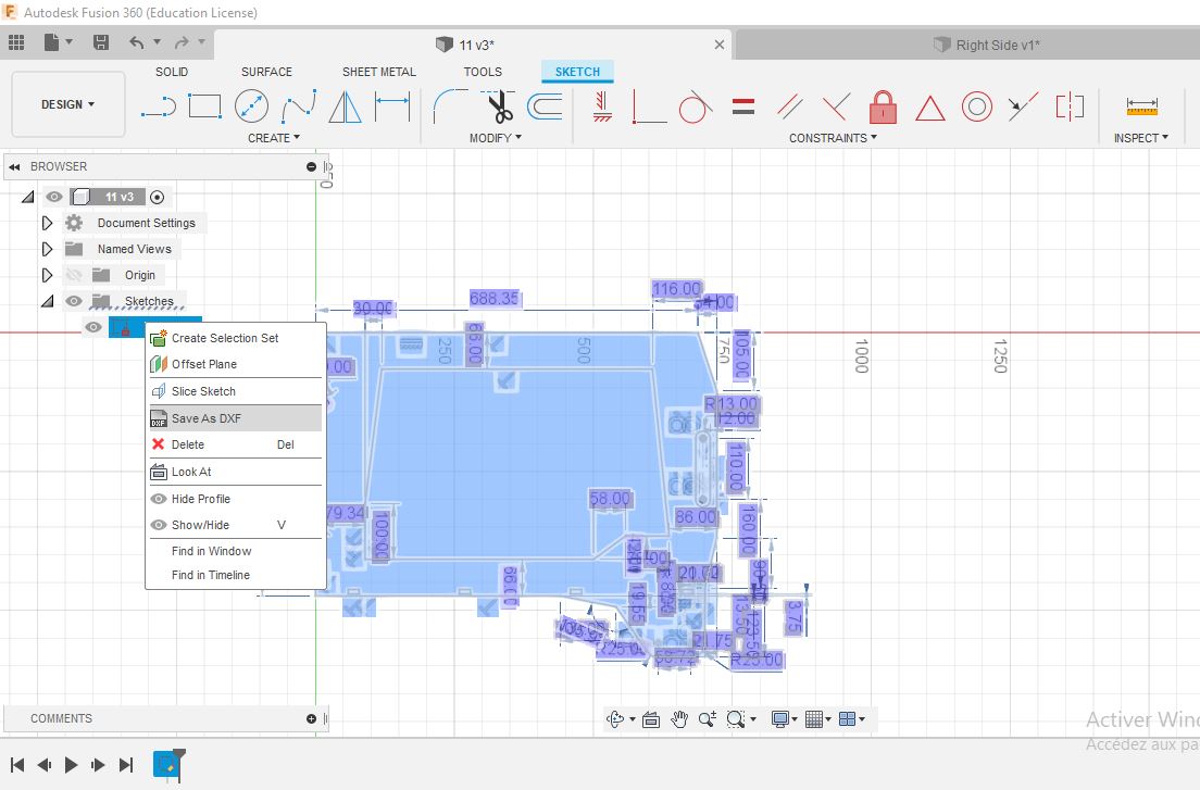
Download Files: Right side DXF
- Solidworks:
-Sketch Parameter
Sketch parameter is a powerfull tool that give us the possibility to modify dinamically the model without editting the sketch from the beginig. Using Solidworks, I will present how to add parameters
Step 1: Go to tools and choose Equations
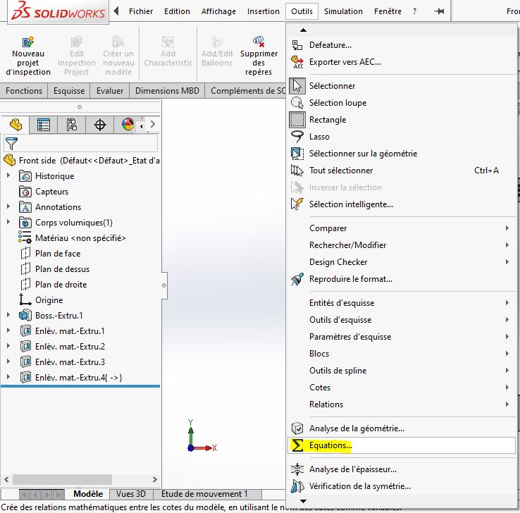
The following window will appear. After that enter the parameters you want, and press ok:
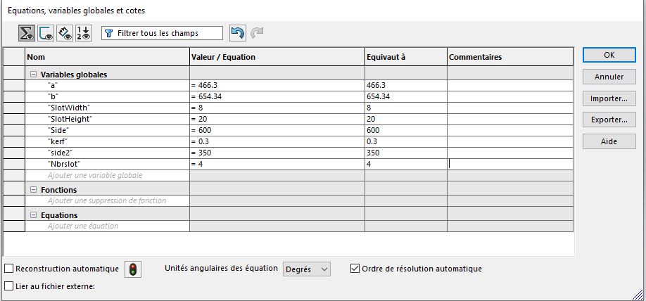
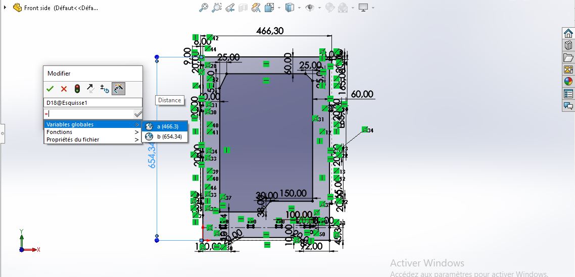
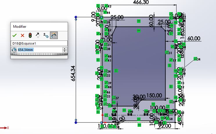
You should use the parameters during the sketching proccess and enter them when you are using the dimensionning tool: just press ‘=’ and then choose the correct parameter.
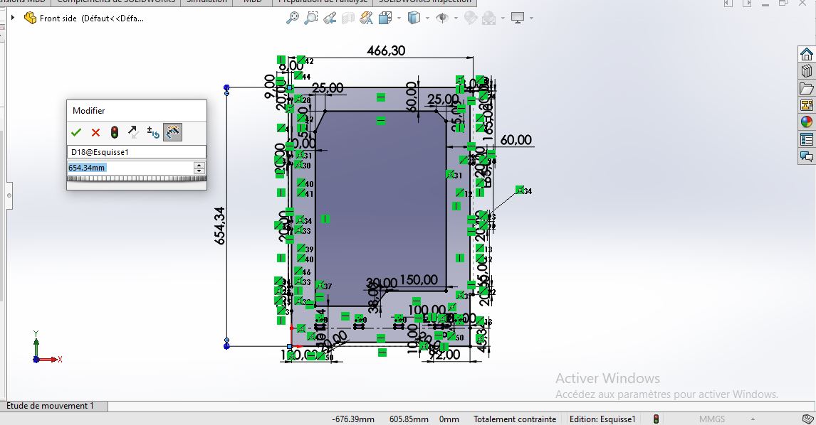
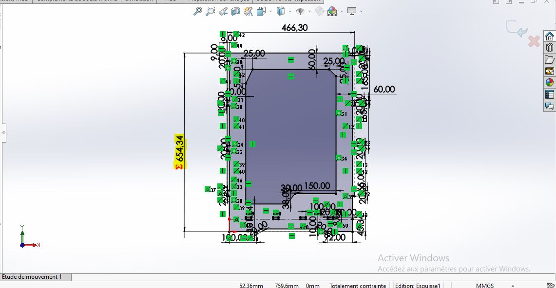
Exit the sketch and you will find your parameters in feater manager under Equations folder:
you can now modify the model using directly the parameters in Equations folder. (without editing the sketch)
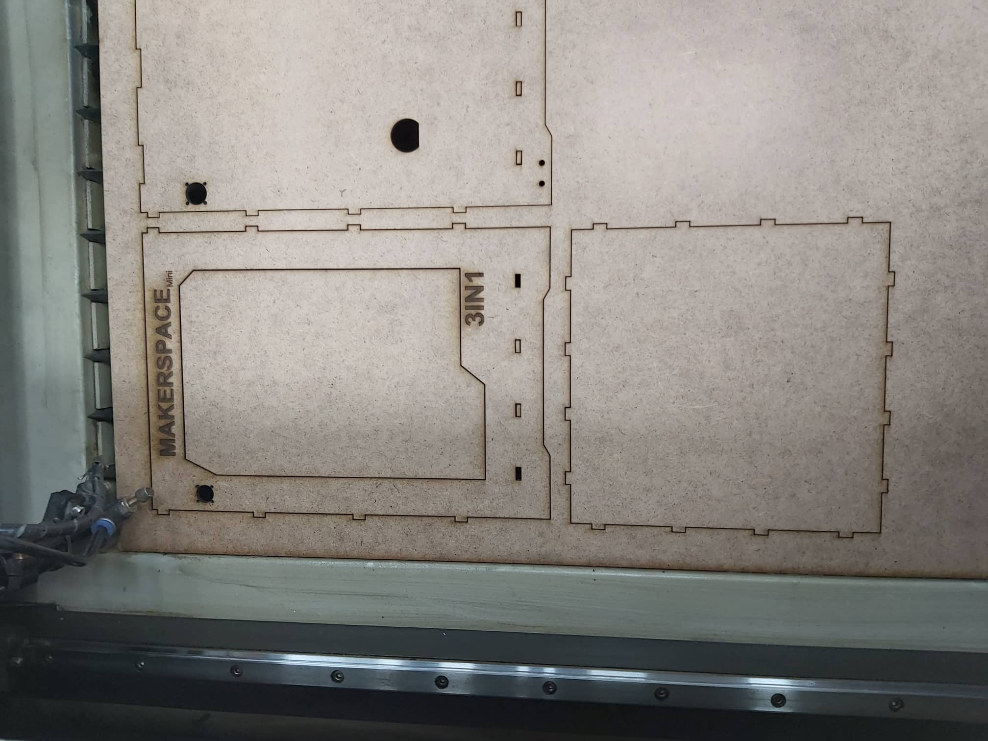
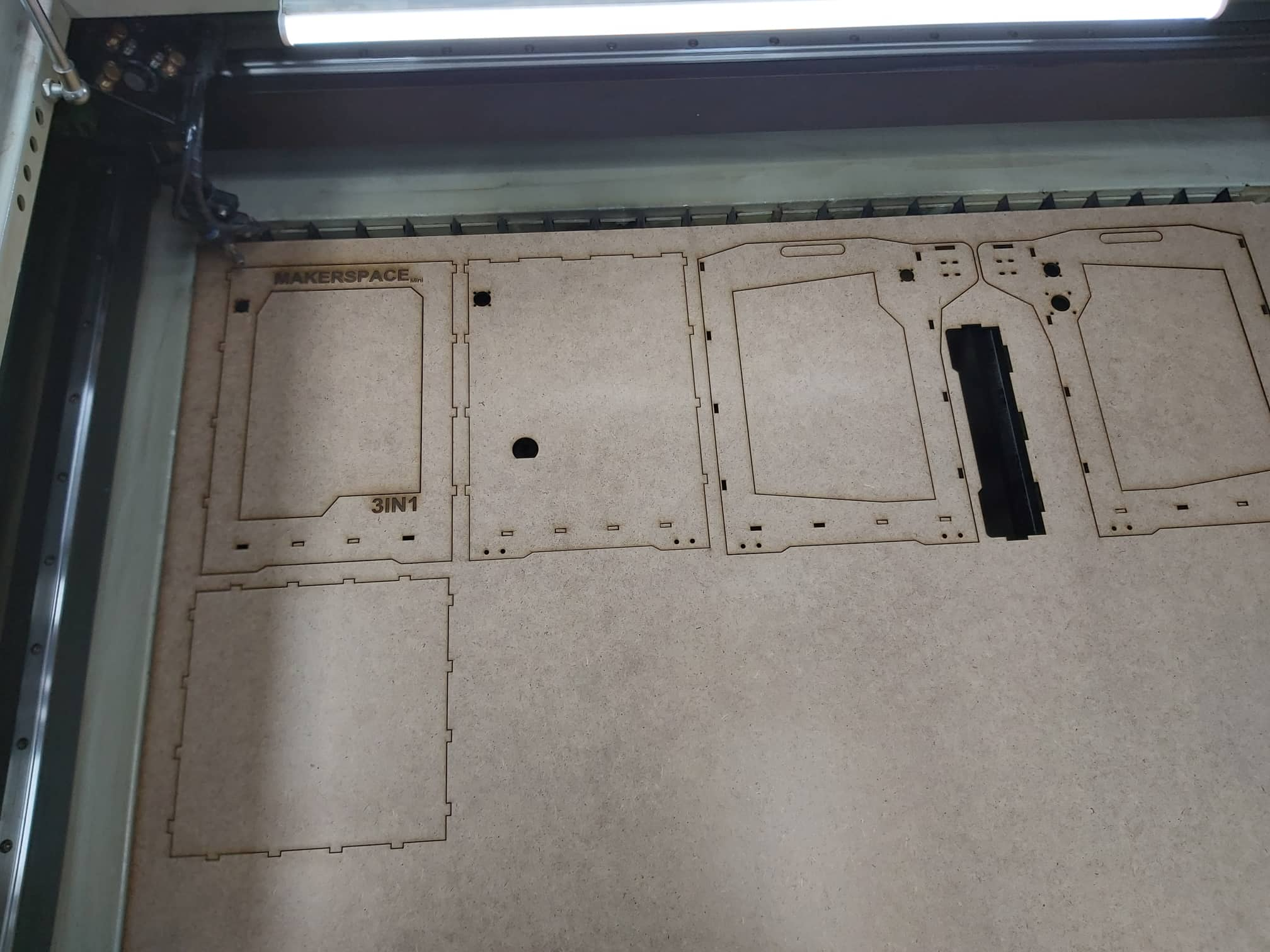
To make a small mock-up of the machine with 3mm MDF, I scaled all the frame parts with scale tool by 0.4 and then I made a drawing file to place all the parts on the same sheet for laser cutting. To do that follow the steps:
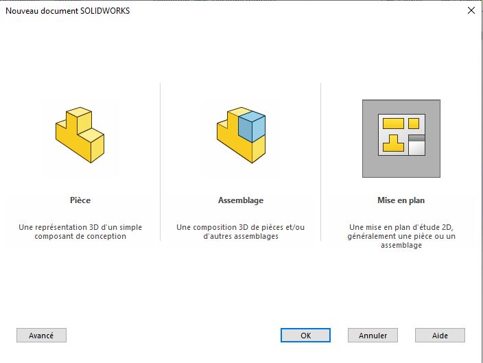
1- Start a new drawing file
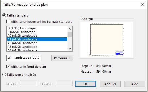
2- Choose your paper size. In our case I will use A1 size.
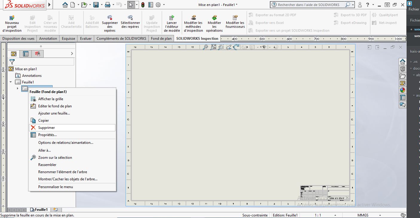
3- Delete the paper background (we need only th frame li,es without background)
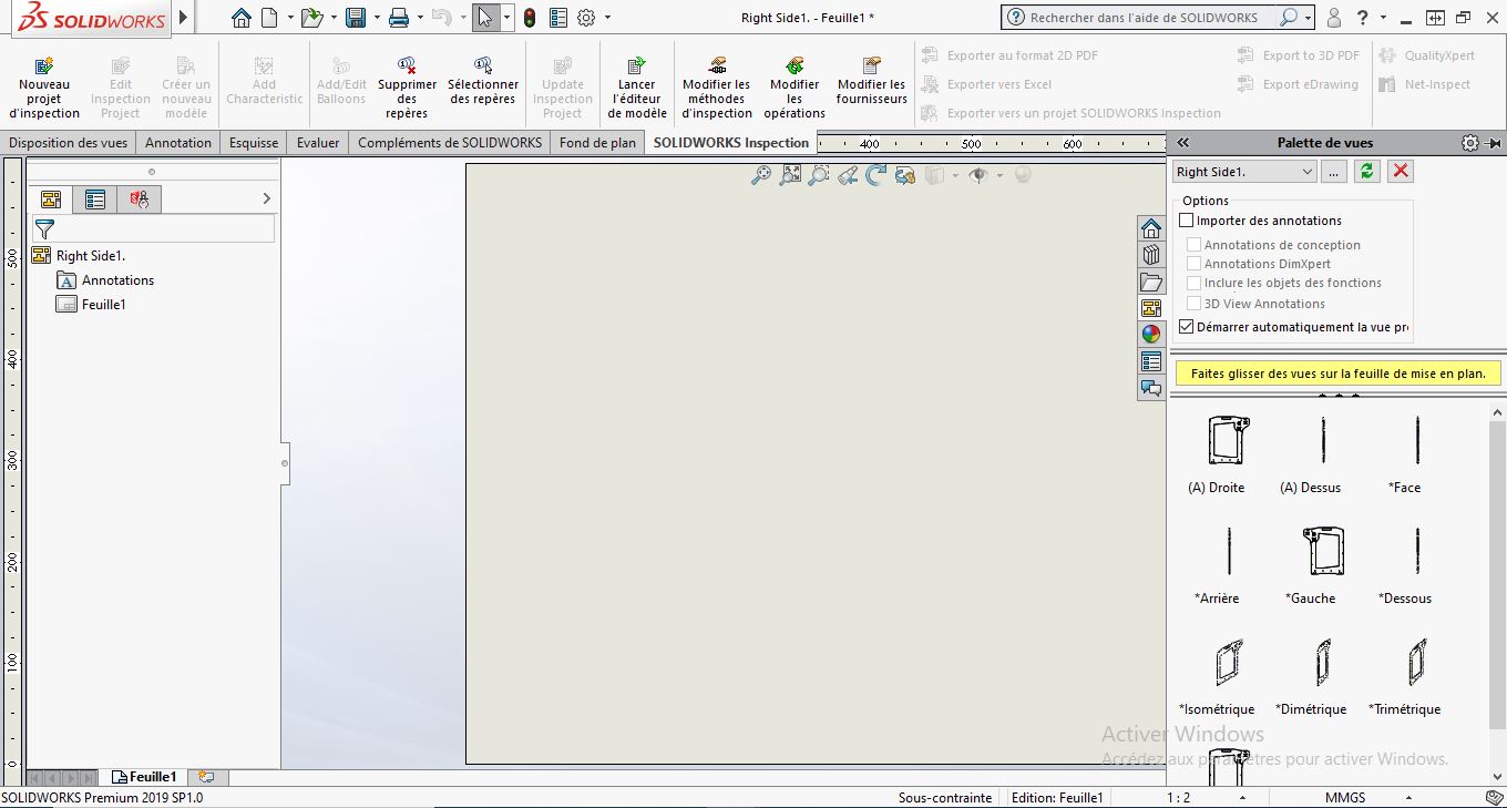
4- Import part and then drug and drop in the workspace
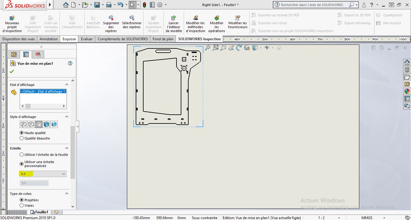
5- Make sure you select the right scale to the drawing file
6- Import part by part to the drawing
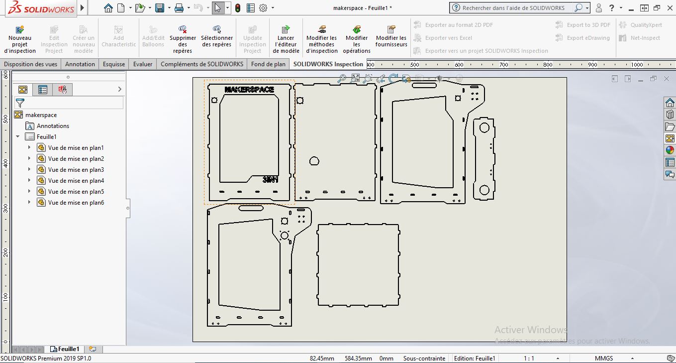
7- Save as DXF
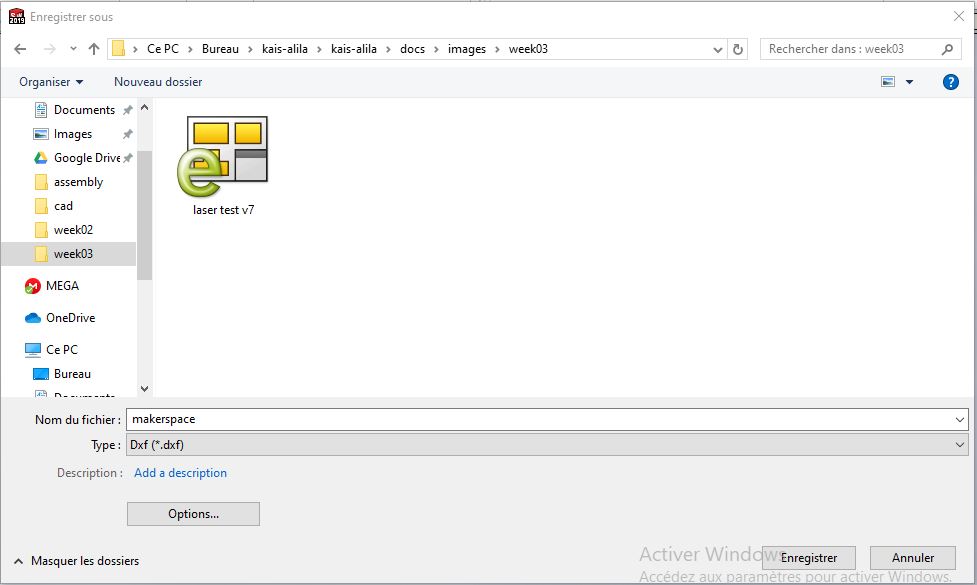
8- Import the model in RDworks (Laser software), st the right parameters and setting based on the group assignment test
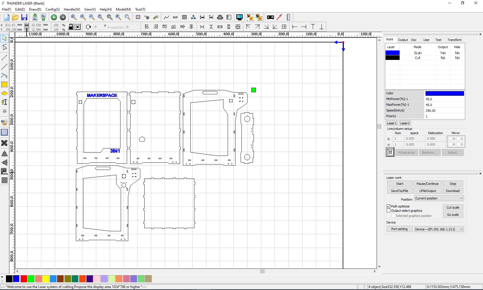
Note: Make sure that the engravin ‘scan mode in RDworks’ will be done before the cutting process
9- send the file to the machine
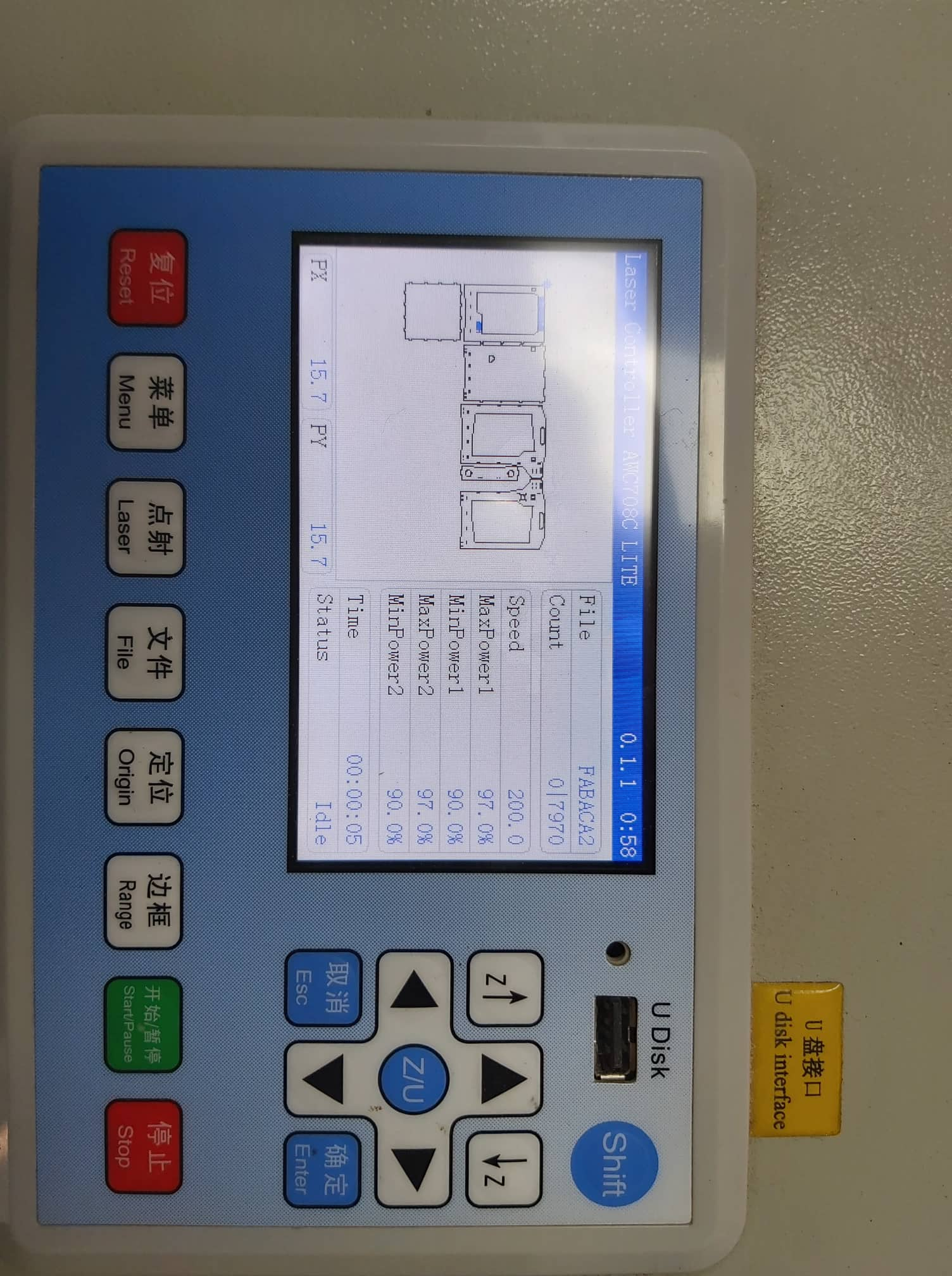
10- Put the MDF in the machine and then set the focus, fix the origin , and then press range to check the job area
11-Start the job
Download Files: Solidworks Drawing file ; makerSpace DXF file; makerSpace RDworks file
Vinyl cutter:
I decided to cut the Fablab logo. So to get the vectors from the logo, I’ve just used a JPG image and then convert it to vectors using the machine software.
Download Files: [Fablab Logo JPG ] (https://gitlab.fabcloud.org/academany/fabacademy/2020/labs/kamplintfort/students/kais-alila/raw/master/docs/images/week03/Fablab%20Logo.png), CutStudio file
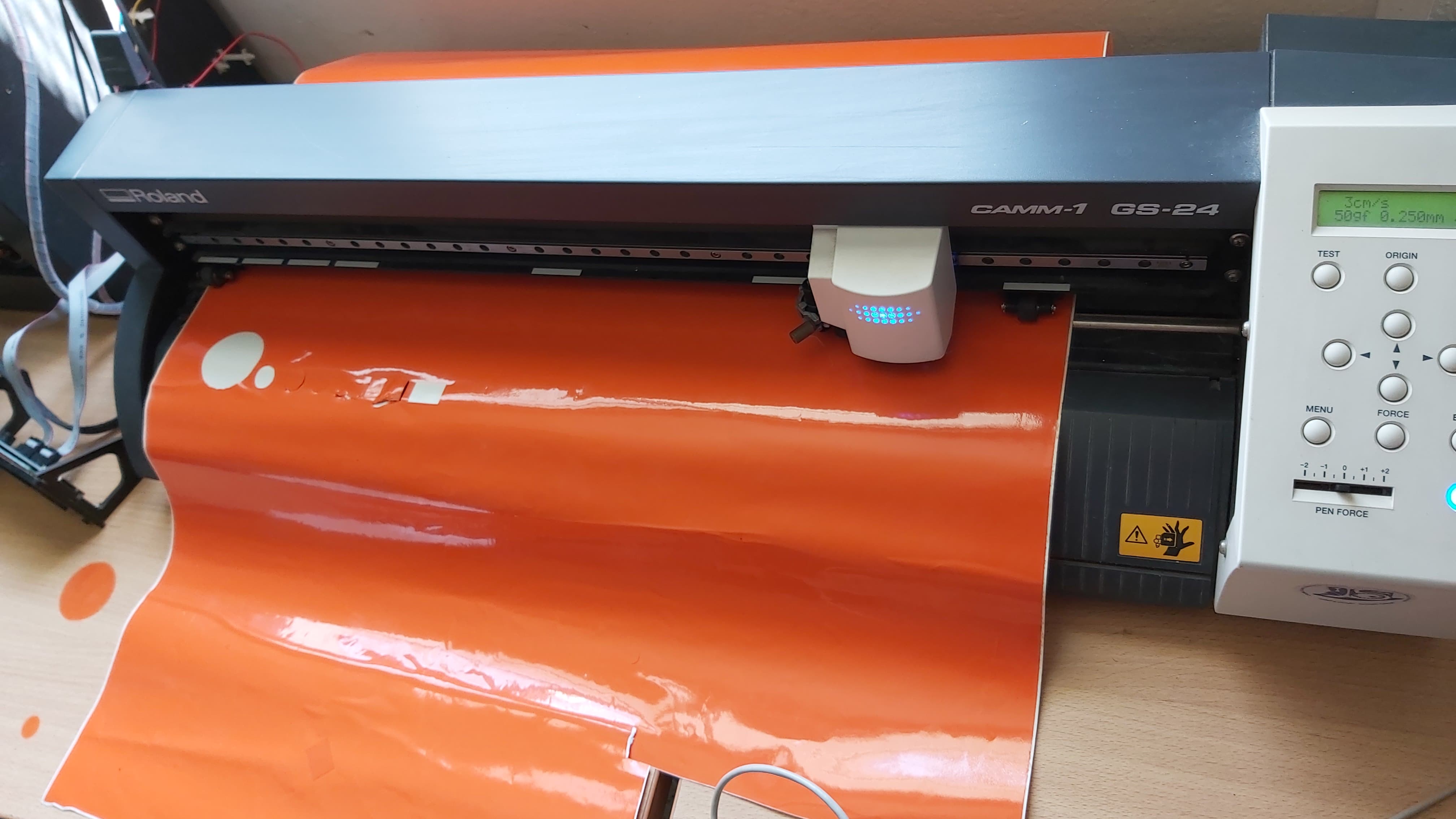
For vinyl cutting, We are using Roland Camm1 GS-24 and CutStudio software to command the machine. You can get the software from roland Website
Using Cut Studio:
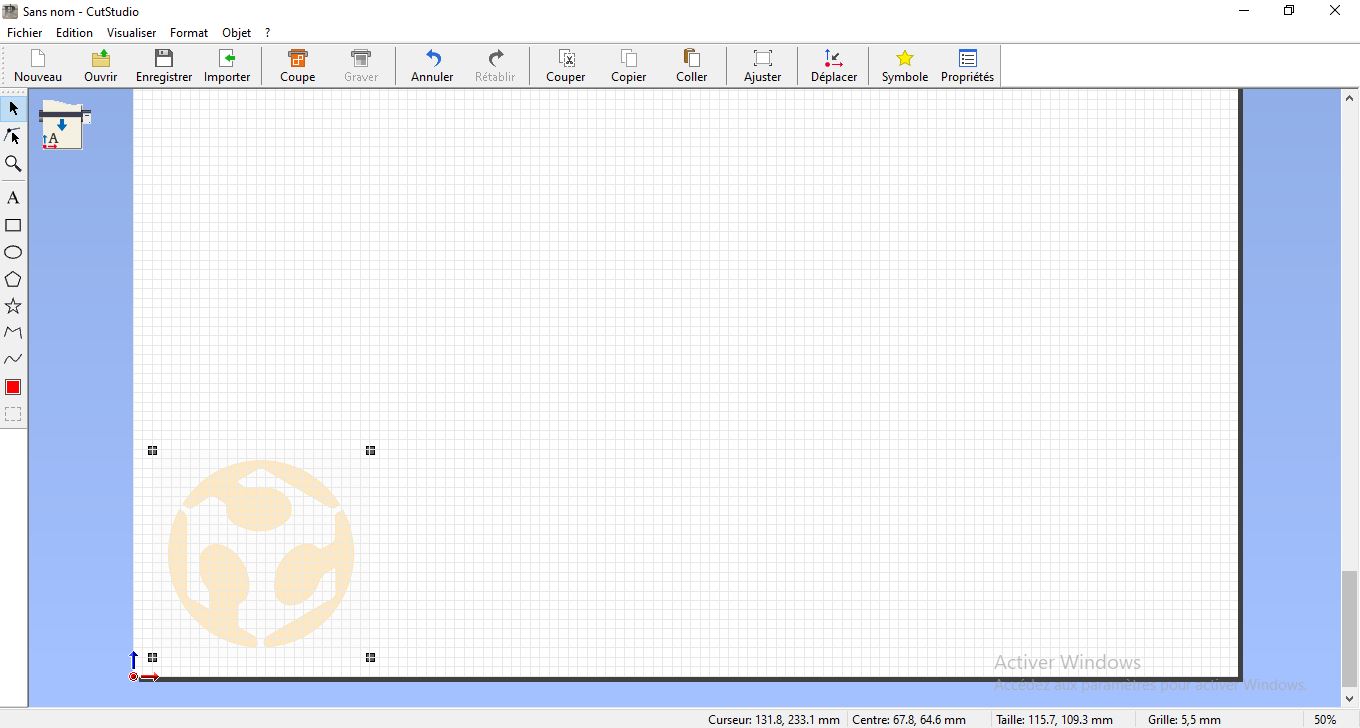
1- Import the jpg image
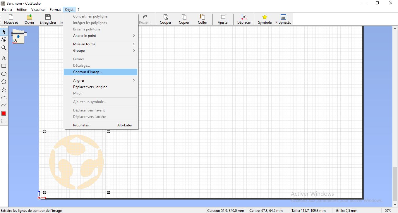
2- Extract lines and vectors using cutstudio tools. Object >> Contour image
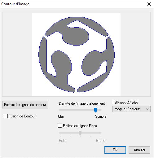
3- Change with the parameters to get better contour and then press OK
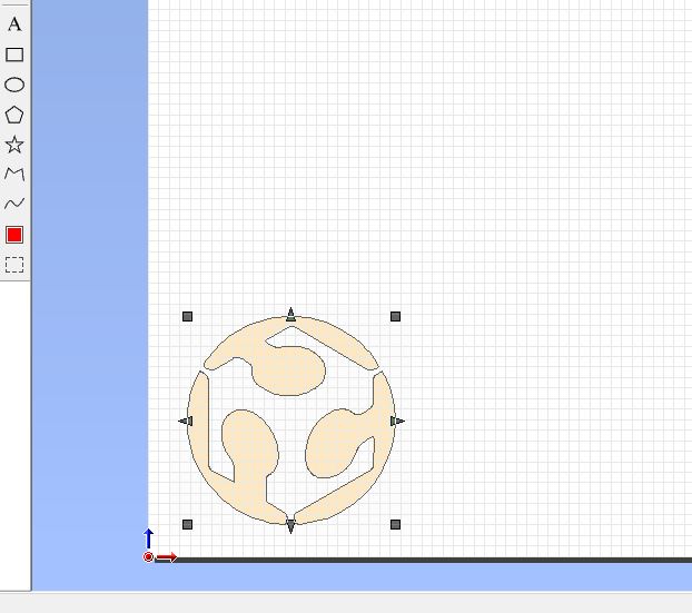
4- Change the color of the trace and add a rectangle to cut it after
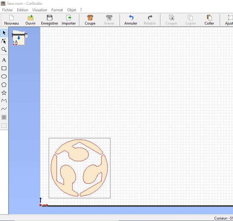
5- go to cut menu and start cutting.
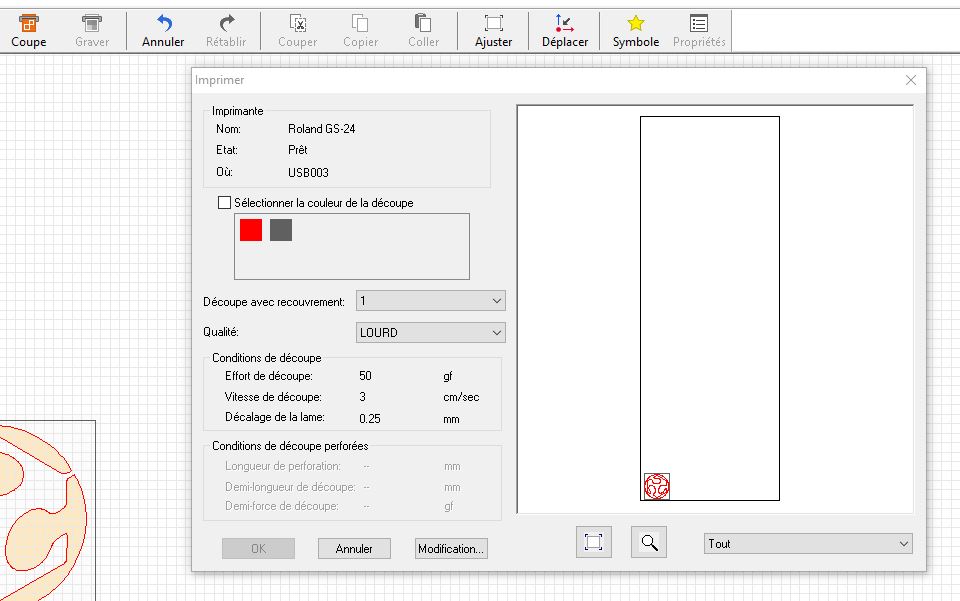
On the ROLAND GS-24 … I’ve set the Force of pen on 50gf and I’ve decrease Speed @ 3cm/s I’ve charge the media inside machine and get from machine the real dimensions.