5. Electronics production
This week I worked on defining my final project idea and started to getting used to the documentation process.
Group Assignment: Characterizing the machine
Here is the link for the groupe assignment page
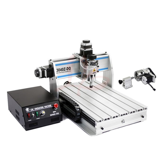
For this week’s group assignment we had to characterize the specifications of our PCB production process on our CNC 3040. The software that we used for milling was Fab Modules, online at Mods and send nc files trough Mach3 software sender.
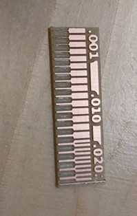
We did a linetest using these two files:
-
linetest.png to milling the traces with 1/64 (0.4mm)bit;
-
linetest.interior.png to cut the outline with 1.4mm bit.
Before attempting to mill we had set the machine as follows:
-
prepare a sacrificial plane;
-
using the double-sided adhesive tape, attach the 20mm MDF plane to the table; then attack the FR1 base on the sacrificial plane;
-
attach the milling bit in the collet and make sure it is 2 or 3 mm from the surface of the FR1;
-
zeroing the Z height, dropping the tip on the plane, making sure that the Z can theoretically get off at least the right amount to be able to mill.
-
zeroing the X and Y axes starting from the left-bottom side of the FR1 board.
Software
The software that we used for milling was Fab Modules, online at FabModulesormods and send nc files trough Mach3 software sender.
Fab Modules is a browser-based CAM system, which allows to generate toolpaths for and control lasercutters, CNC-mills and waterjets commonly found in fablabs. we test the machine
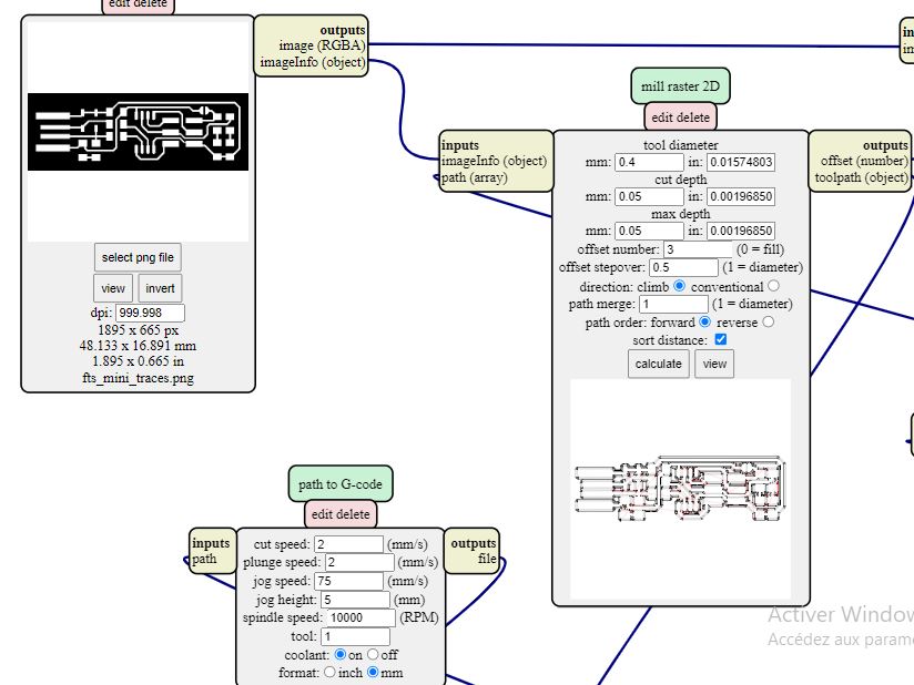
For Trace

open the software click on the mouse’s right button.choose programes , click to open an server programe and choose shobot mill 2D png
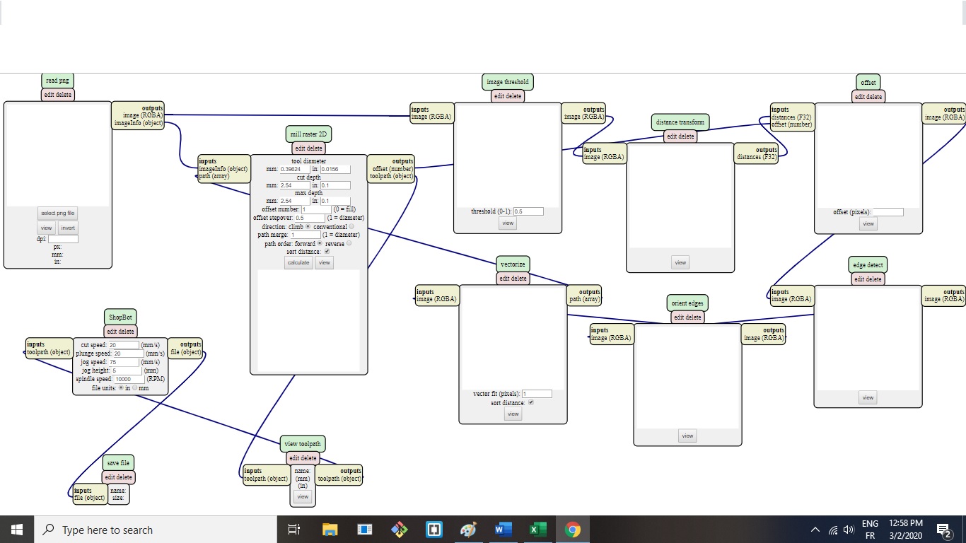
Then import the png file:
-
Configure the tool diameter and the depth of the cut: in our case we have 0.4mm tool and -0.05mm depth to have good result. We also selected the option fill with typing in offset number.
-
For the cut settings, after many tests and researchs we found these settings: 4 mm/s as cut speed, 2 mm/s as plunge speed, 75 mm/s for jog speed and 5 mm for jog height. the spinle speed is 10000 Rpm.
-
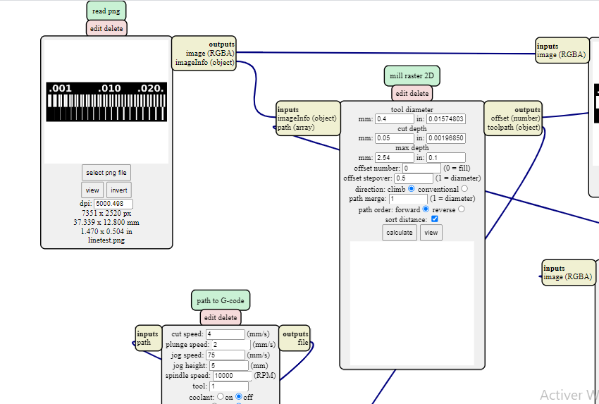
Then press Calculate
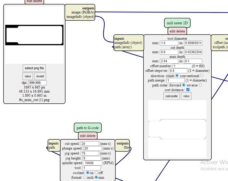
For Outlines
For outlines cut, we just chnage the tool diameter and the same process.

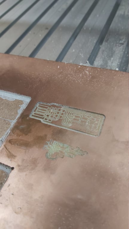
Result LineTest
Individual assignment
FAB ISP - Brain version
1. Milling
Once the hardware has been prepared as described above in Hardware section of the group assignment, I’ve generated NC-code CAM trough Fabmodules again, starting from Brian’s PNG
I’ve used 2 mm/s Cut Speed and decreased Spindle Speed around 10000 rpm
And for cut:
Result:
2. Assembling:
Prepare the following Components to assembly on the PCB:
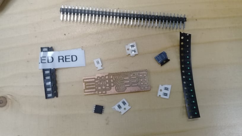
- 1x ATtiny45
- 2x 1kΩ resistors
- 2x 499Ω resistors
- 2x 49Ω resistors
- 2x 3.3v zener diodes
- 2x LEDs
- 1x 100nF capacitor
- 1x 2x3 pin header
Note:
The components that must be installed in the correct orientation:
- 3.3v zener diodes
- LEDs
- ATtiny45
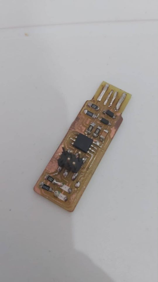
At this point brush all the pads with the flux, and then start soldering.
At the end of the assembly work …
3. Programming:
The first step was to download Zip file ,Zadig-USB and WinAvr
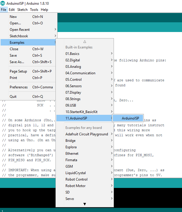
Then open the arduino frameware and run the ArduinoIsp program , to find it you should go to file ->example ->Arduino ISP and it will transfer the arduino into prgrammer.
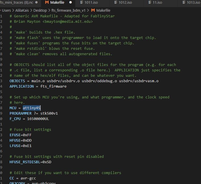
Disconnect your arduino and extract the Zip file that you downloaded previously then open the makefile , we need to make some changes so it becomes able to work with arduino.
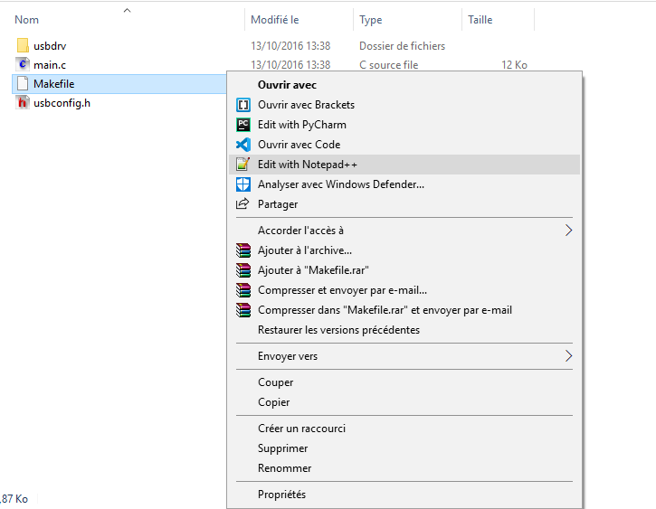
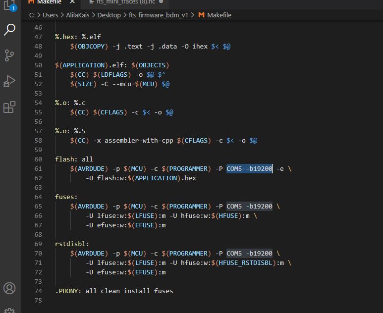
You should chnage te MCU to attiny45 and the programmer and also same parameters in the commands flash , fuses and rstdisbl ( Port and baudrate)
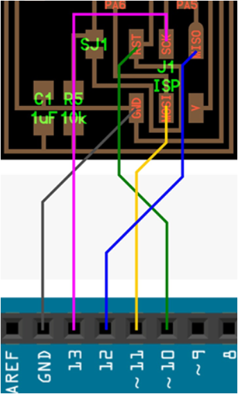
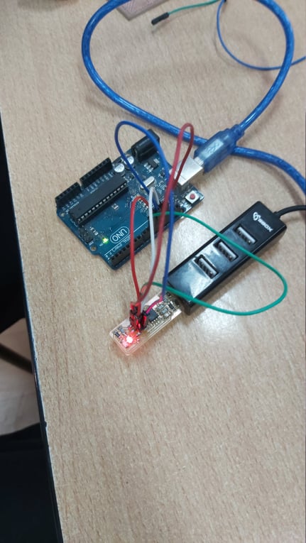
After saving all those changes , I connected the fabisp to the arduino as followed
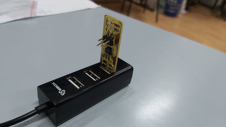
At this point, we should check all the connections, you should use a USB HUB to connect the fabISP and protect your laptop. Connect the arduino first and then plug the usb hub.
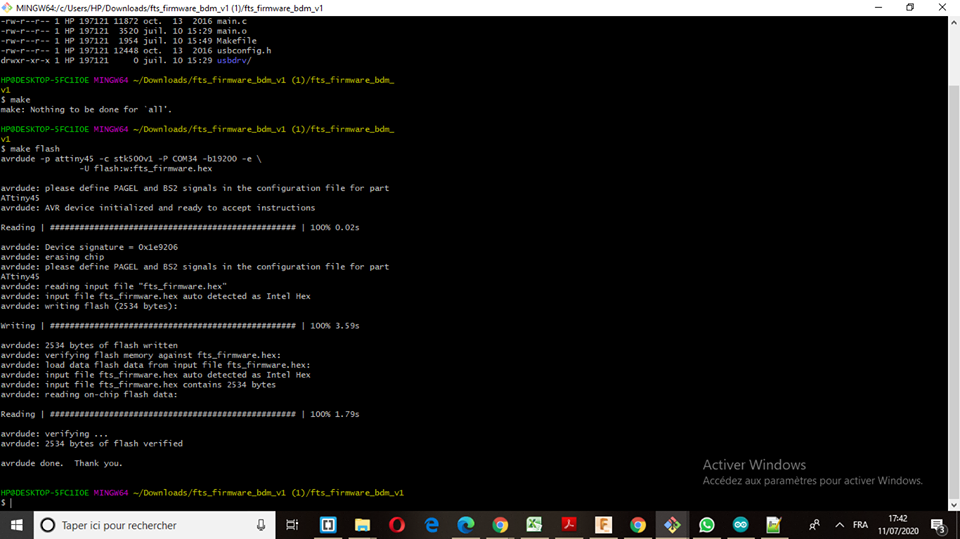
Then open git and write special commands to program the ISP using arduino
- make flash to send the code to program the ISP
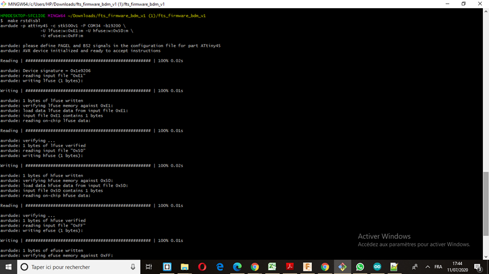
- make fuses to upload settings
- make rstdisbl to disable one of the pins to work as a reset

Now disconnect the arduino and all the jumper cables and keep the fabISP connected.
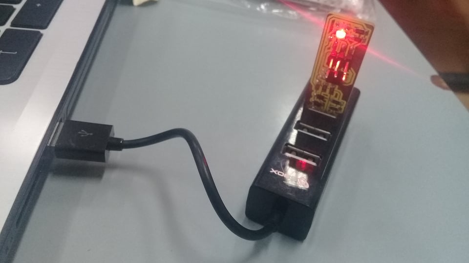
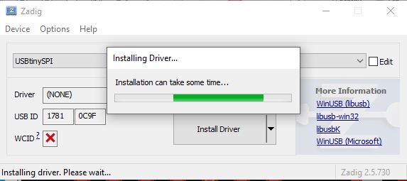
After that you should install the driver for the fabisp to be recognized with the computer using Zadig software. search for USPtinySPI and click on Install Driver.
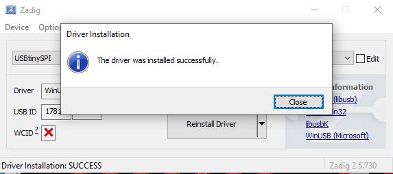
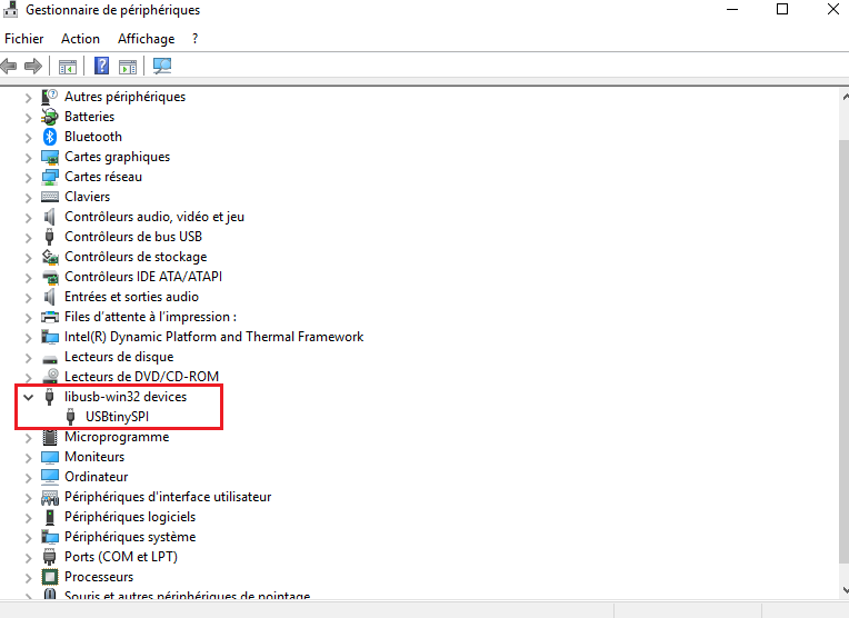
at this point your laptop could recognize your ISP:
Other Software For Electornic Production
In our fablab we usually use FatCAM as post prcessor to generate the G-code. Down bellow all the steps documented for the fablab members in How to use the CNC for PCBs using FlatCAM?
I will use the hello board as an example for FlatCam
- Step 1: FlatCAM Reads only gerber file for the trace and for the outlines, exported from the desing software like EAGLE, ad it also supports drill files like XLN alo exported from EAGLE. EAGLE is a powrfull software that uses a CAM Processor to export all the needed layers and jobs for a complete board.
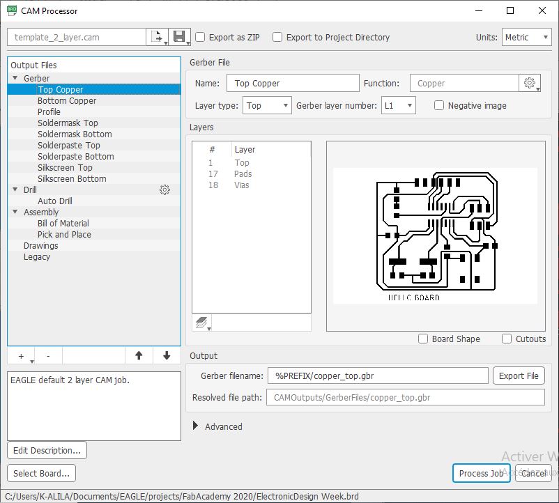
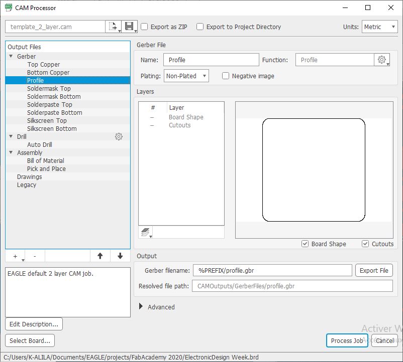
a. After desinging the board you should open CAM Processor tool for EAGLE to export the needed files for FlatCAM.
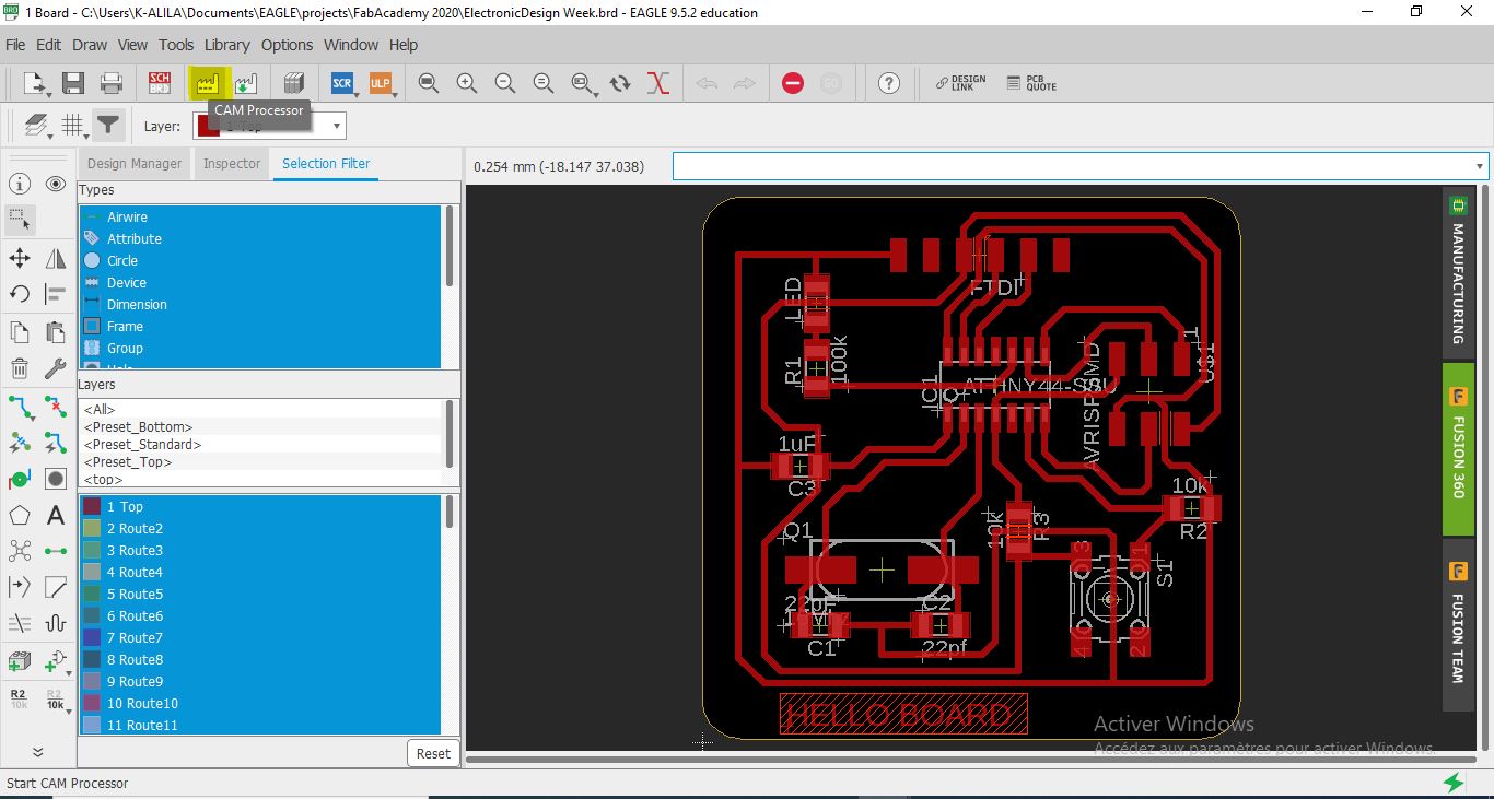
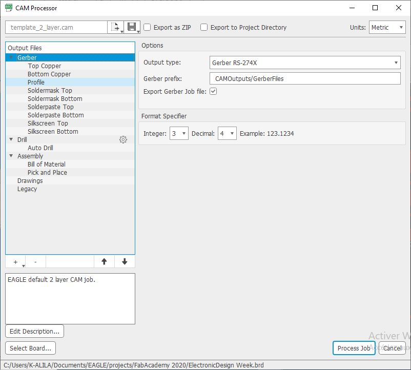
b. With this tool you can choose the layers and the job for your board and the export it gerber For example we usually need the Top Copper layer, the Bottom Copper and the Profile. It depends on your manufacturing process and your board complexity
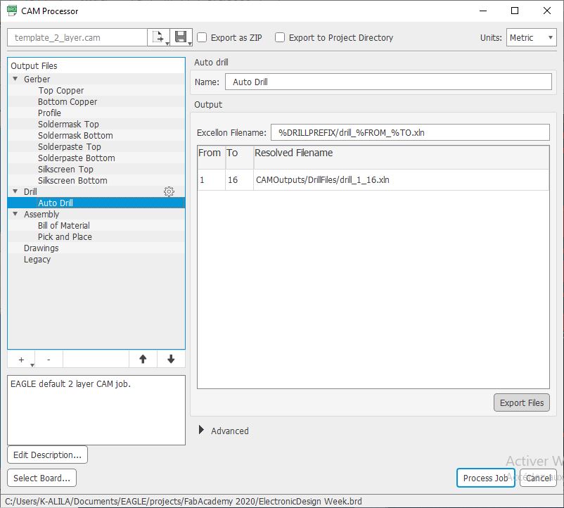
If you have trough all components you can export the drill file XLN file.
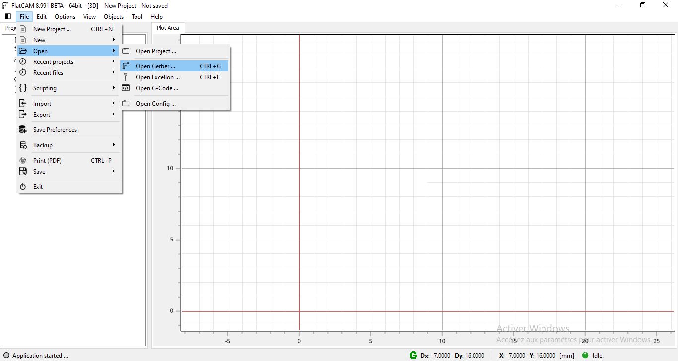
- Step2: FlatCAM lets you take your designs to a CNC router. You can open Gerber, Excellon or G-code, edit it or create from scatch, and output G-Code. Isolation routing is one of many tasks that FlatCAM is perfect for. It’s is open source, written in Python and runs smoothly on most platforms.You can download FlatCAM from this link
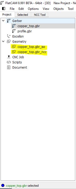
a. Open the gerber file and excellon files into flatcam.
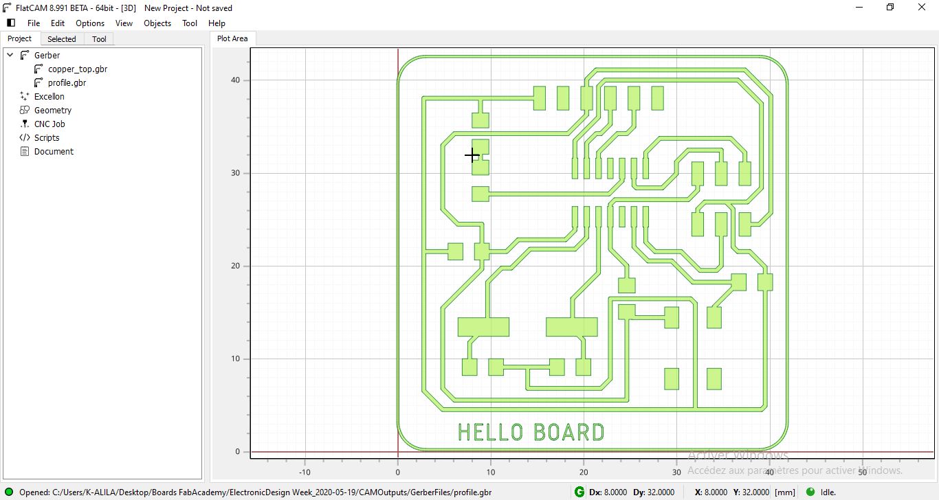
NOTE: To move the trace or the profile, you should select all then move the groupe. Also You should import all the gerber files and the drill file together at the same time before moving because you may lose the correct position of each layer. lat cam postion the layers correctly when you import them all after that you can ove the groupe. If you import the top copper for example and move it then import the drill file you miss the correct position of the drills on the board.
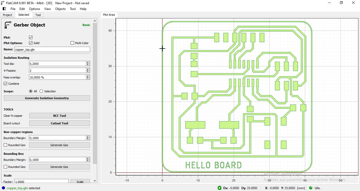
b. Double click on the top copper gerber file of the project manager. here where you will choose te tool diameter and the number of passes for the tracce. You can also use the NCC Tool (Non-Copper Clearing) process to mill the surface where we dont need copper and chose another tool diameter and the milling depth to make the process faster. After all that press Generate Isolation Geometry
c. At this point you generated a geometry based on your design that defines also the tool path.
Previous Settings:
-
Tool diameter for trace: 0.2mm (it depends from the tool you have at the lab)
-
Tool shape for trace: V-shape (Generally used for pcb milling and for easy bord. For complex ones you need circular shape)
-
Tool diameter for NCC & Cutout: 1.5mm (it depends from the tool you have at the lab)
-
Tool shape forNCC & Cutout: Circular shape, Flat EndMill
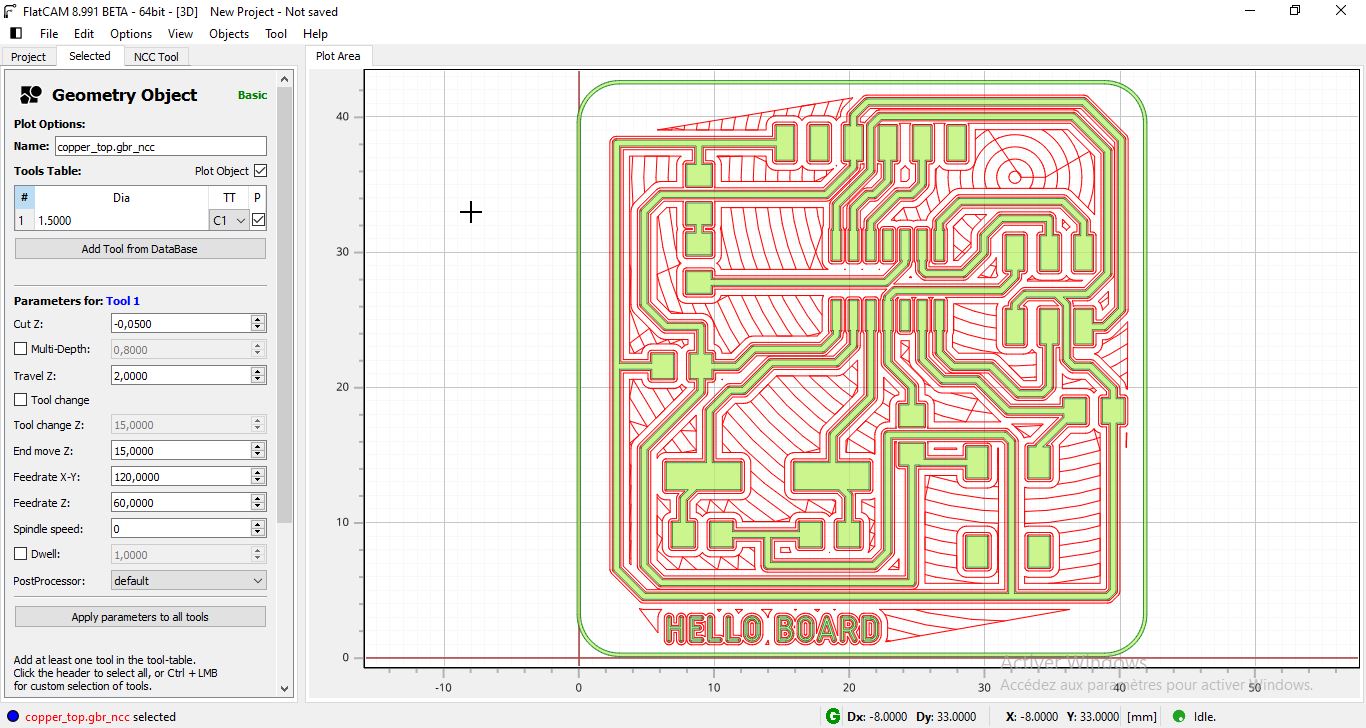
d. The next step is to generate the toool path to have the g-code at the end. Double Click on the Geometry generated on the previous step. and enter the machining settings like the plunge speed, the cut depth , the default speed …
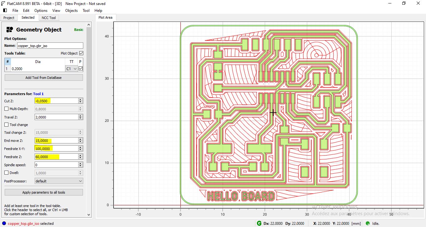
after many tests the best parameters for good quality board :
-
Cut depth: -0.05 mm
-
Tool realese distance: 5mm
-
XY Speed : 100 mm/min
-
Z speed or plunge Speed: 60mm/min
-
Spindle speed: 15000 Rpm (if you have PWM spindle)
e. generate the tool path and finally you will have the g-code by double click on cnc job coammand
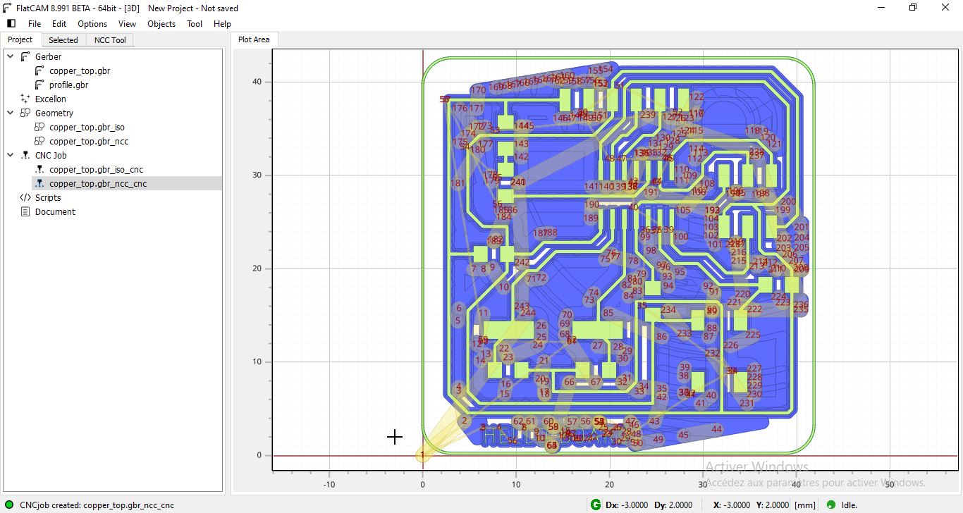
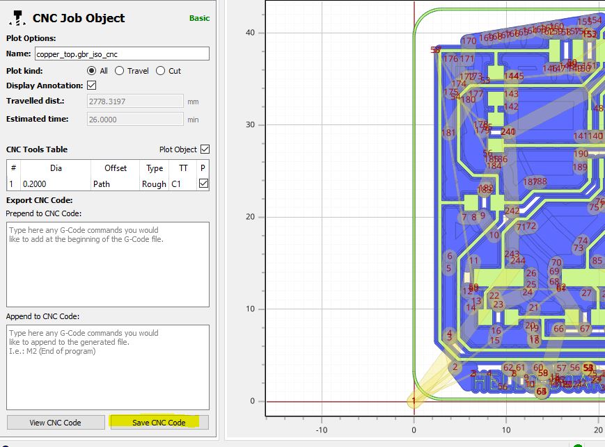
Final step upload the G-code to your cnc and HAPPY MILLING!