8. Computer controlled machining
This week I made something big, designing, modifying & milling my final project machine frame. After testing a small scaled frame with laser cutting in Computer controlled cutting week (Week 3), I did the real size for this week assingnment.
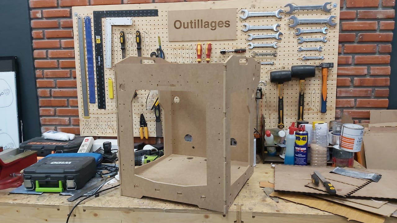
The frame is 752mm height and 466x584mm LxD, I’ve made it in Mdf sheets with a thickness of 8mm and using a flat endmill of 6mm diam.
Group assignment
Here is the link for the group assignment page.
Design
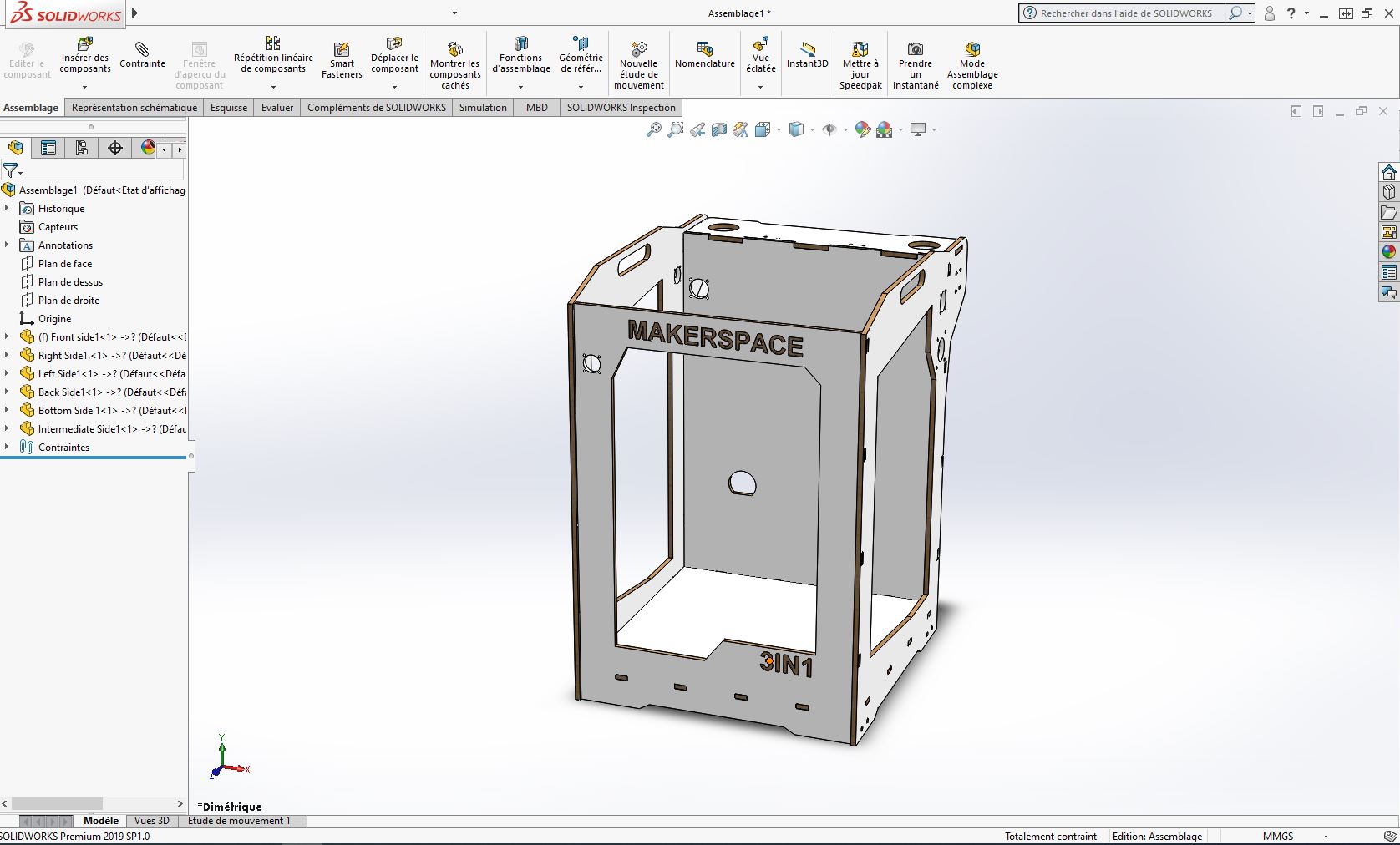
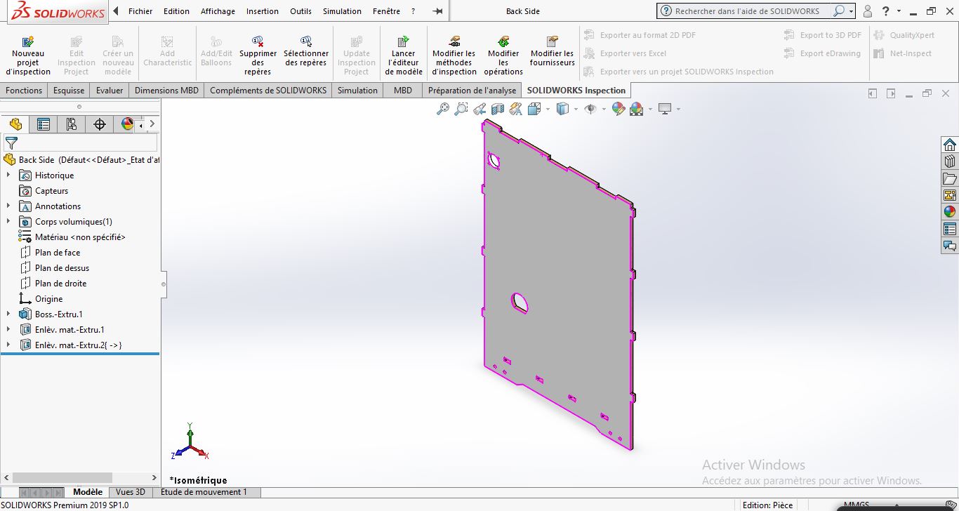
I ‘ve designed it using solidworks during week 2: computer aided design
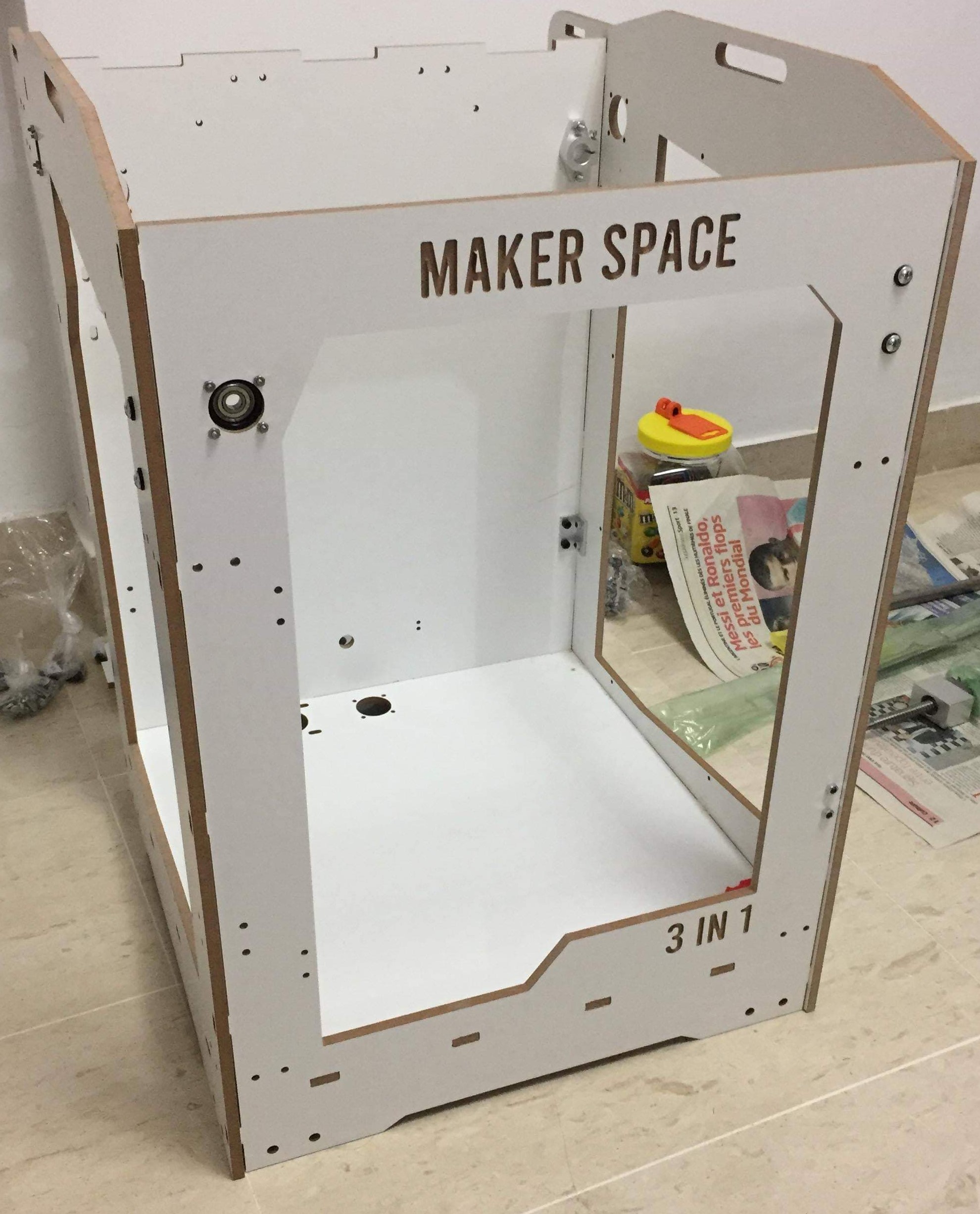
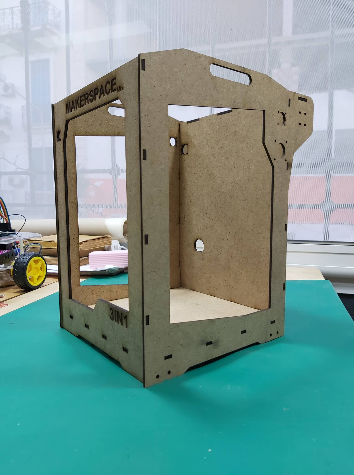
I’ve made some small laser cutter model with 3mm MDF, to test the joints and the assmebly
for cnc cutting, after doing some researchs aboout CNC cutting I found that the machine has some limits like not having 90° angle.
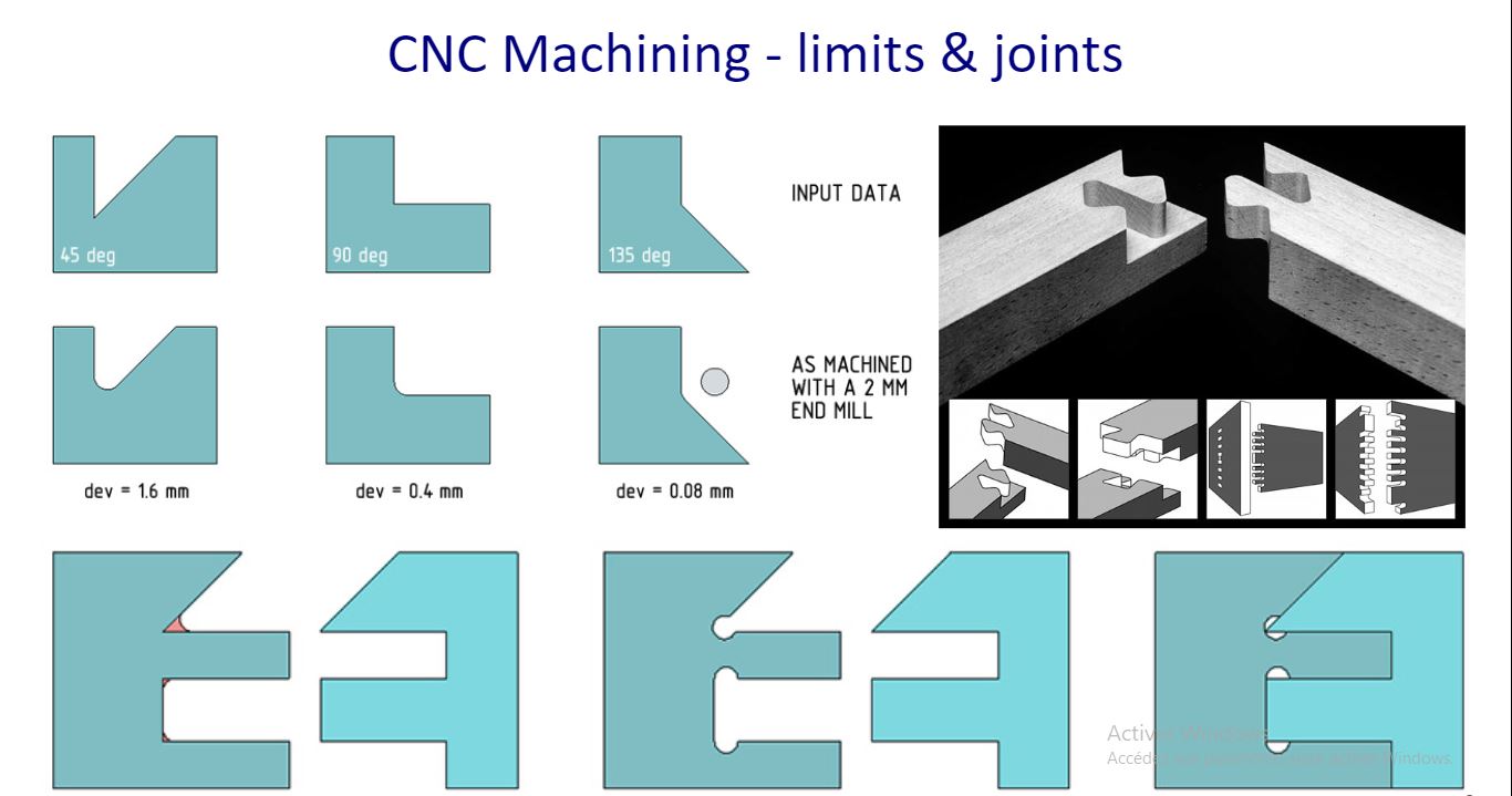
So to solve this problem, we should add DogBones, I added the tool diameter in each 90° angel:
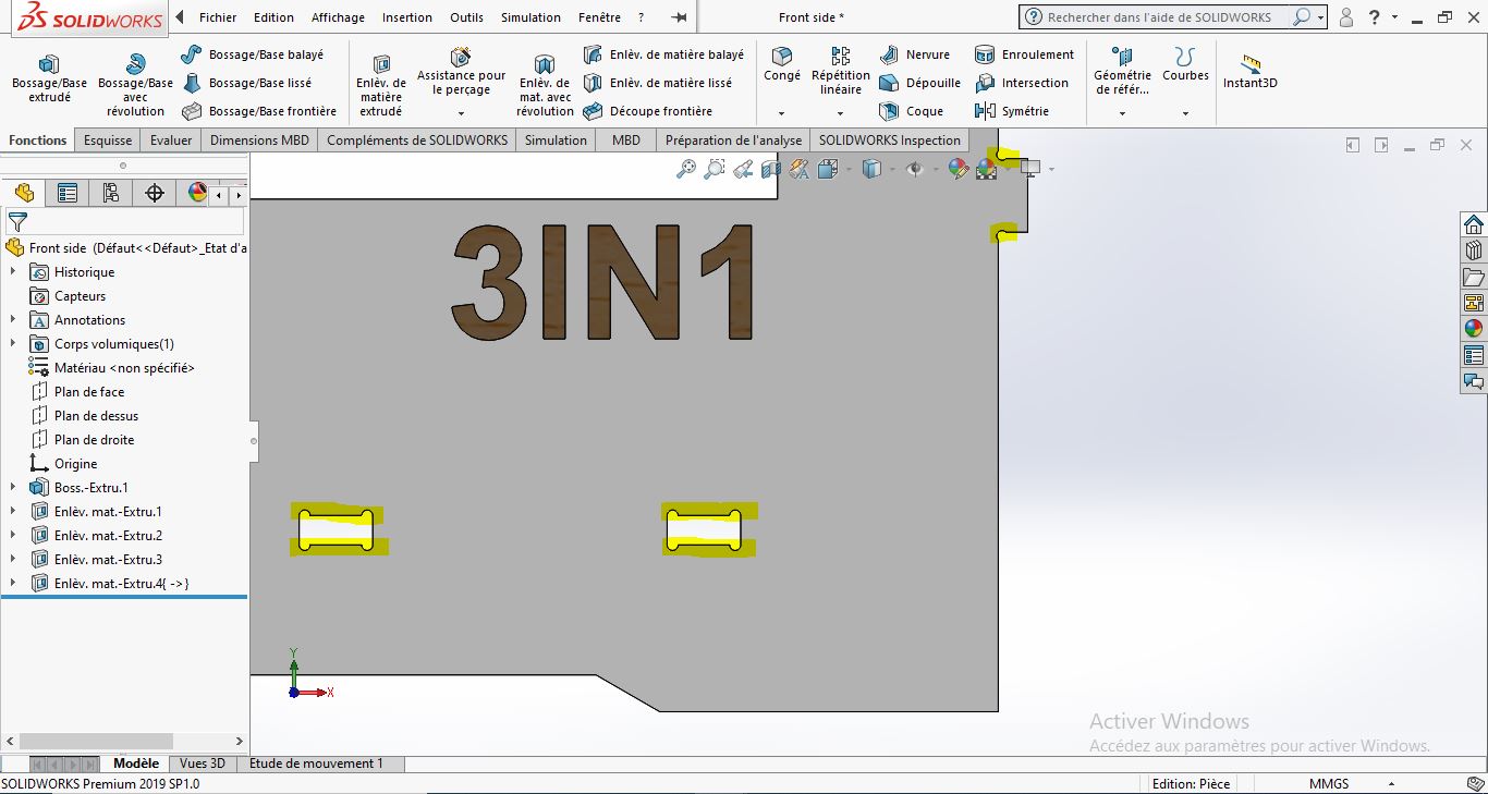
I did the same steps for the rest sides of the machines.
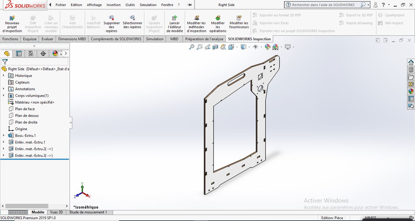
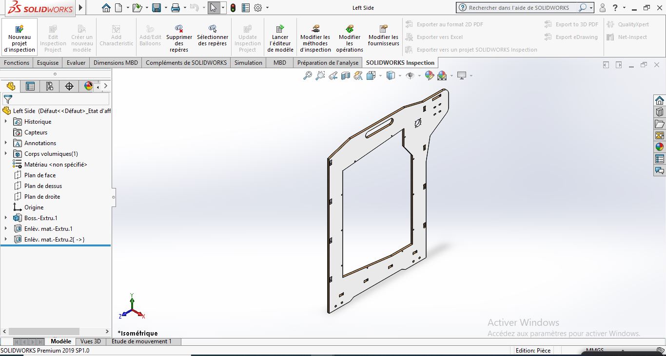
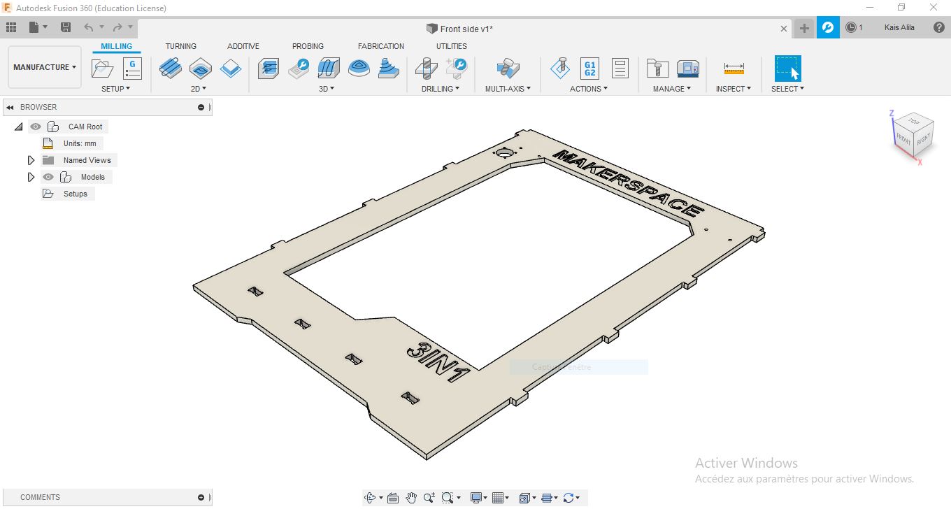
Final model: 
Download Files
Fabrication
To mill all the parts, I’ve produced the GCode through Fusion 360 CAM software.
First, I’ve uploaded the STP file to fusion then open Manufacturing workspace .
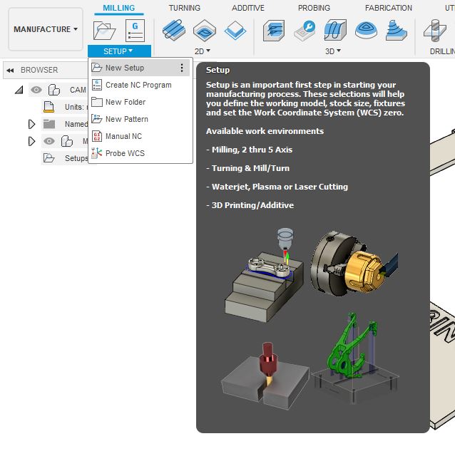
Create new set up to define the stock and set the work coordinate system.
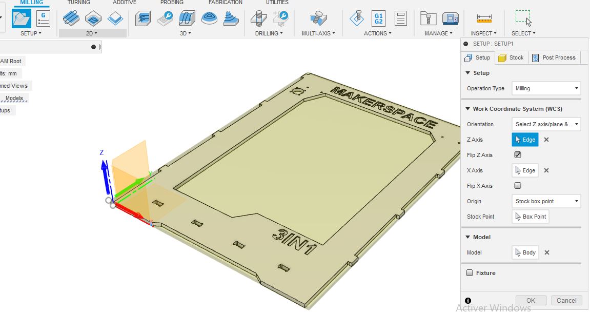
At this point we defined the stock and the coordinates and we should now do the milling operation in order. Note: We should start with inner cutting going to the outer cutting to guarentee a precise result.
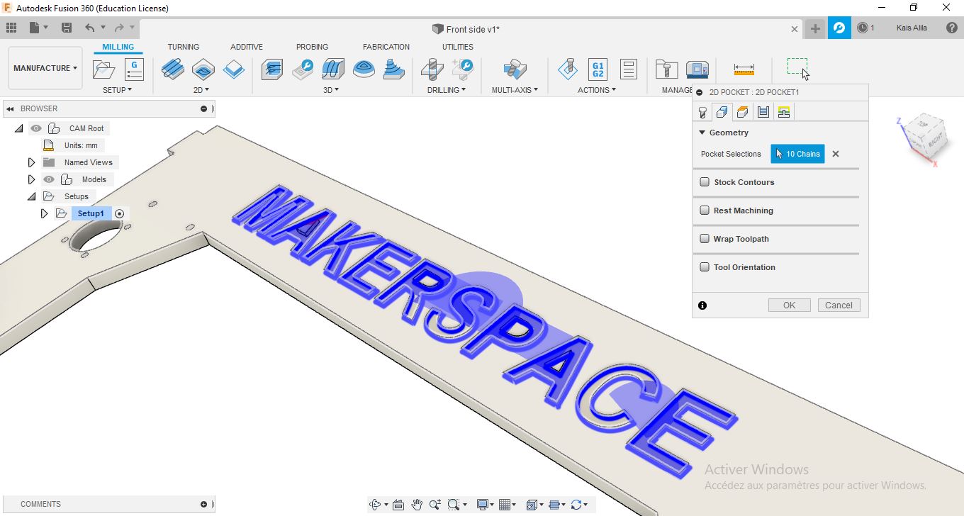
So first, I will start with the pocket operation to mill the leters: 2D >> 2D pocket
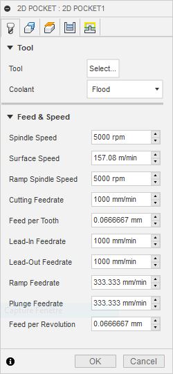
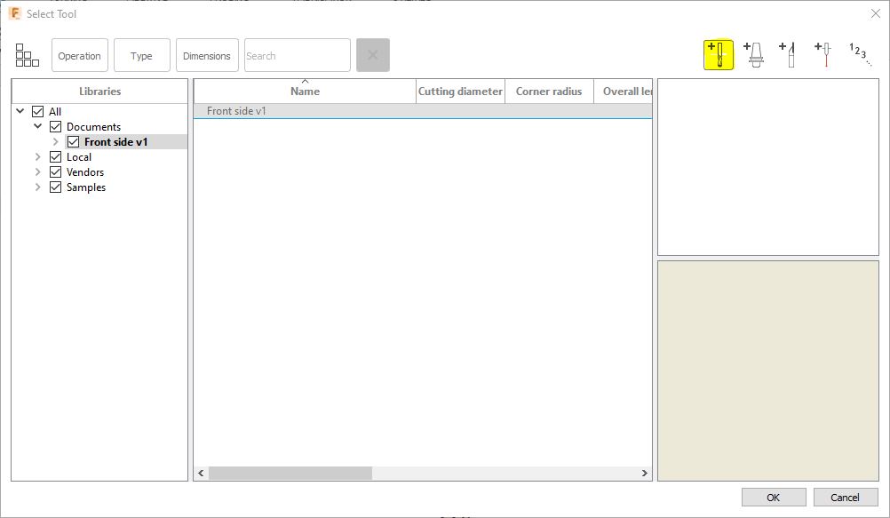
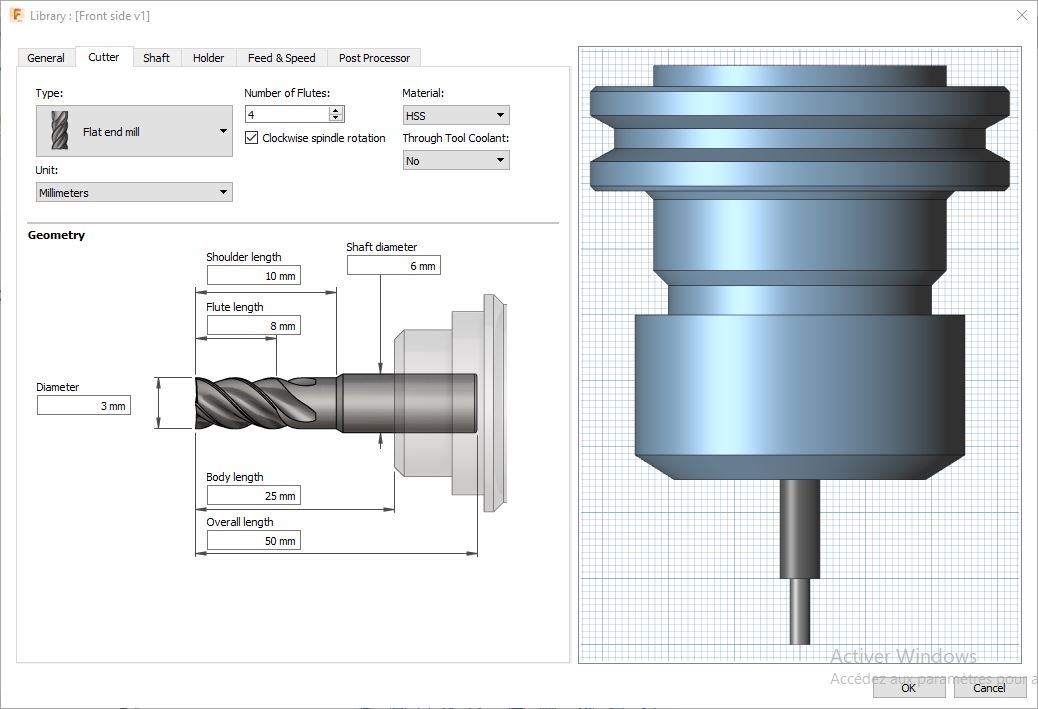
we need to add the tool dimension to the tool library
I am using a 3mm Flat end mill with 4 Flutes for wood cutting.
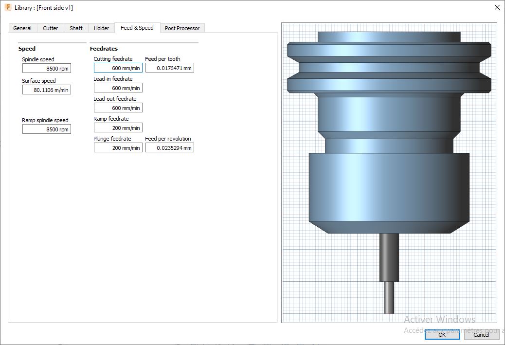
You can set the speed for the tool from the llibrary manager
-
RPM: 8500 Rpm
-
Cutting feedrate: 600 mm/min
-
Lead-in Feedrate: 600 mm/min
-
Lead-out Feedrate: 600 mm/min
-
Plunge & Ramp feedrate: 200 mm/min
Select the geomtry to mill (pocket selection) in our case just select the bottom surface of the leter
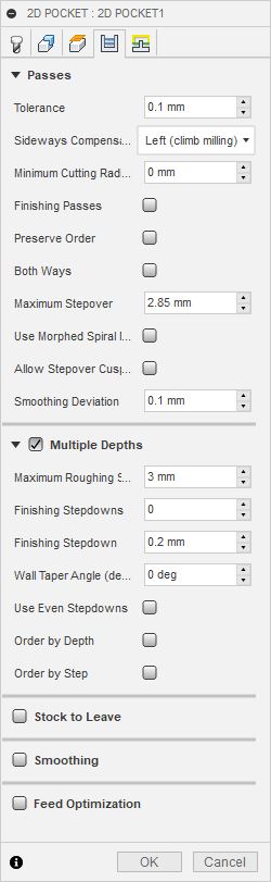
set the passes and multiple depths to make sure that the tool do not cut the wood in one pass
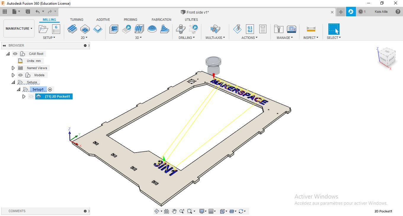
Prss ok and we will get the simulation
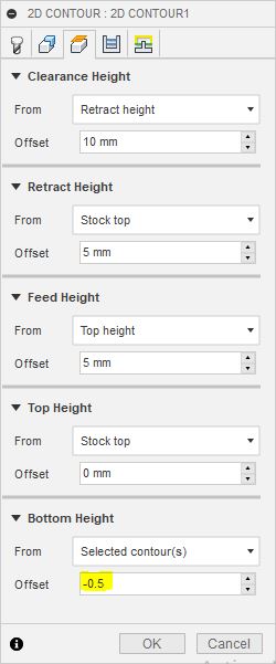
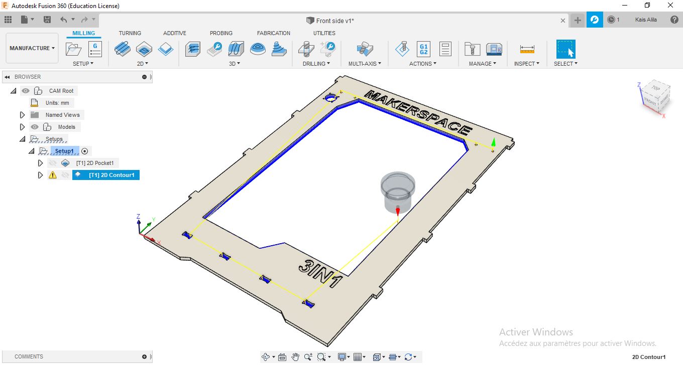
I’ve done after, 2D contor operation. 2D >> 2D contour and select the inner counter like holes and throw all cuts.
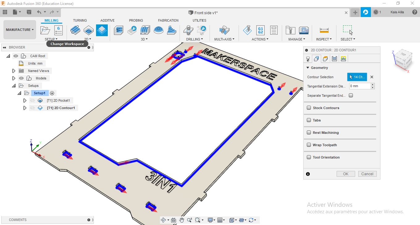
In plans i just set -0.5mm offset for the bottom plan to guarente the throw all cut. and also multiple depths option.
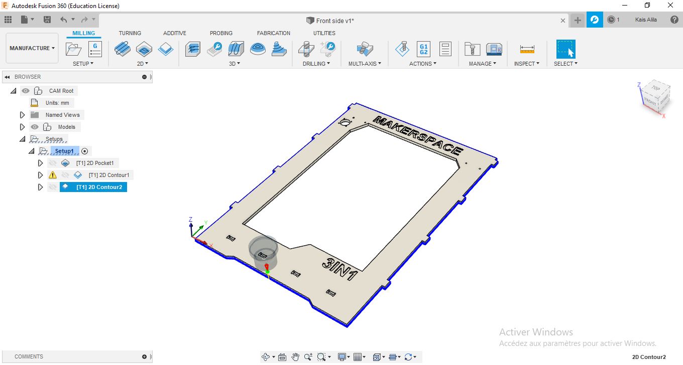
and then another 2D contour operation with the same previous setting for the outter contour
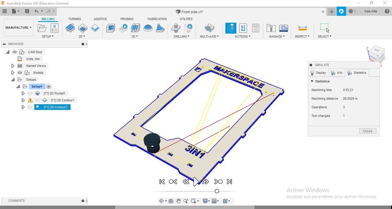
We can simulate the job to check if there is any problem like collisions,.. and we can also have an estimation on the machining time.
To get the G-code, just go to ACTIONS >> Post Process.. Choose the Process Configuration for the machine.
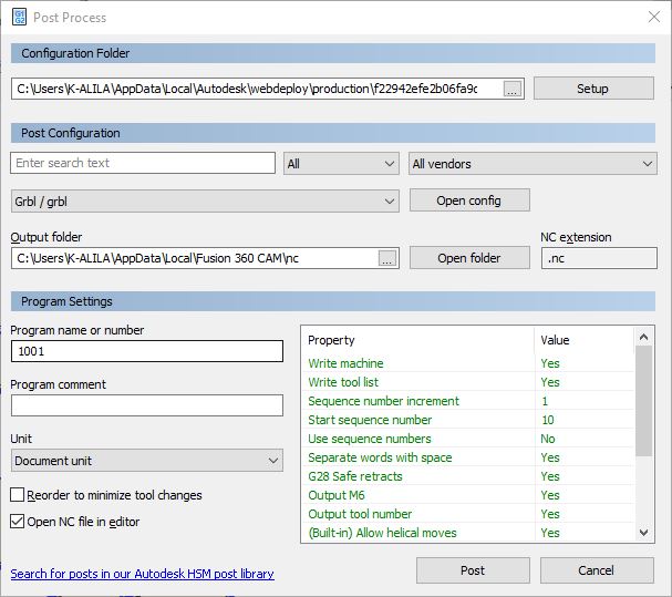
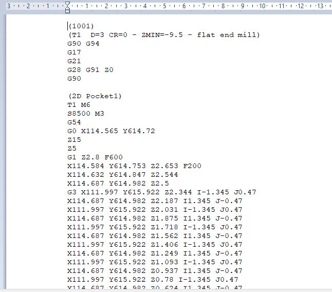
And get the G-Code
Making Process
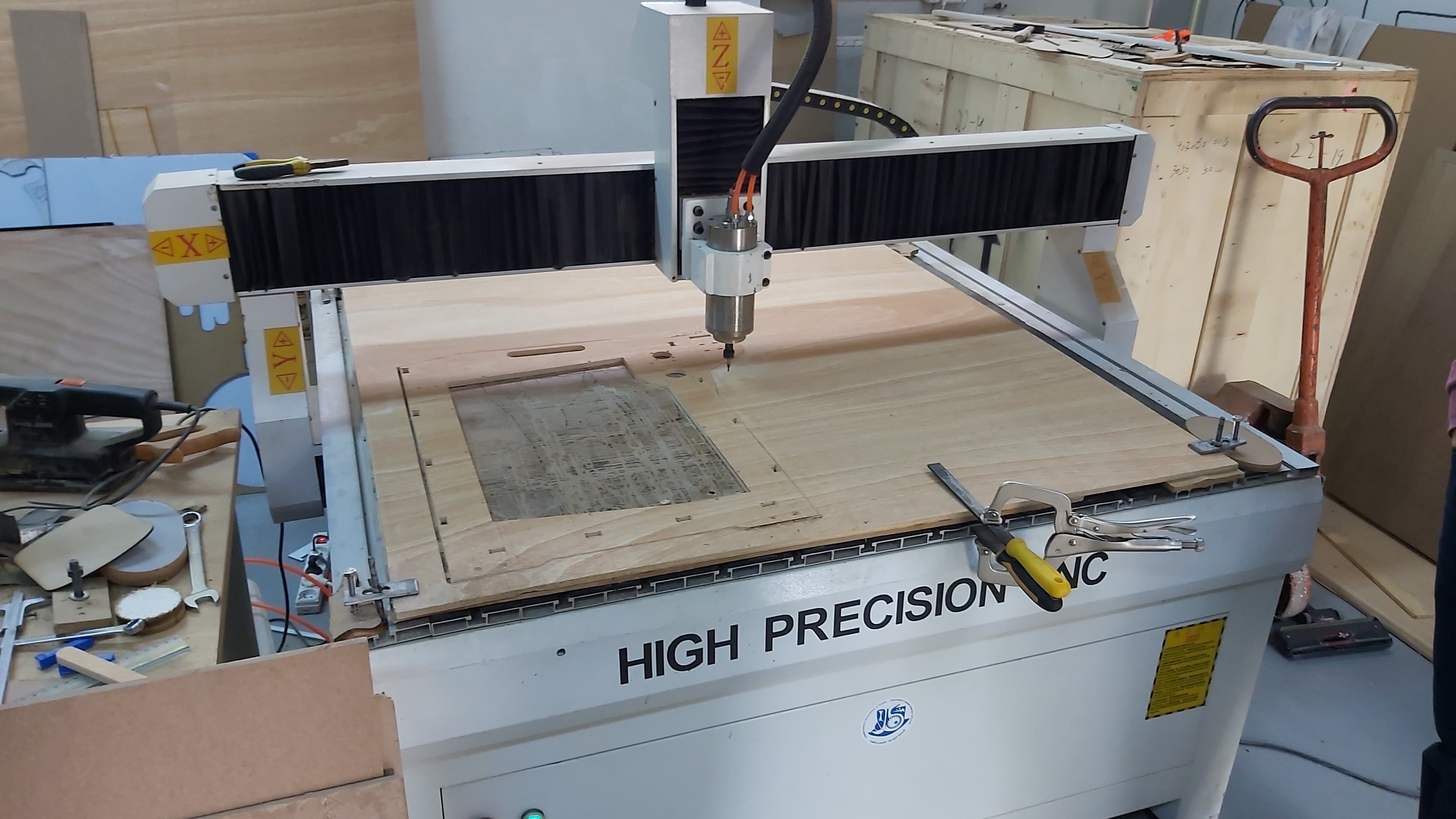
In this assignment, I’ll be using our second cnc machine, Victor VR0907B.
Technical Sheet:
Table dimensions: 900mm x 1000mm
Max working size: 900mm x 700mm
Z-axis travel: 110mm
Table: T-slot
Max. travel speed: 7000mm/min
*Voltage: 220V
Motor: Stepper motor
Spindle speed: 18000rpm/min
Spindle power: 1.5kw
Tool diameter: 3.175 to 6 mm
Accuracy: 0.01 mm
Controller :NcStudio
Software: Type3
Format: HPGL G code
Unidirectional transmission: ball screw
Weight: 300kg
Machine Size: 1000 × 1260 × 1300mm
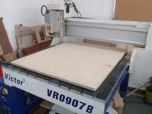
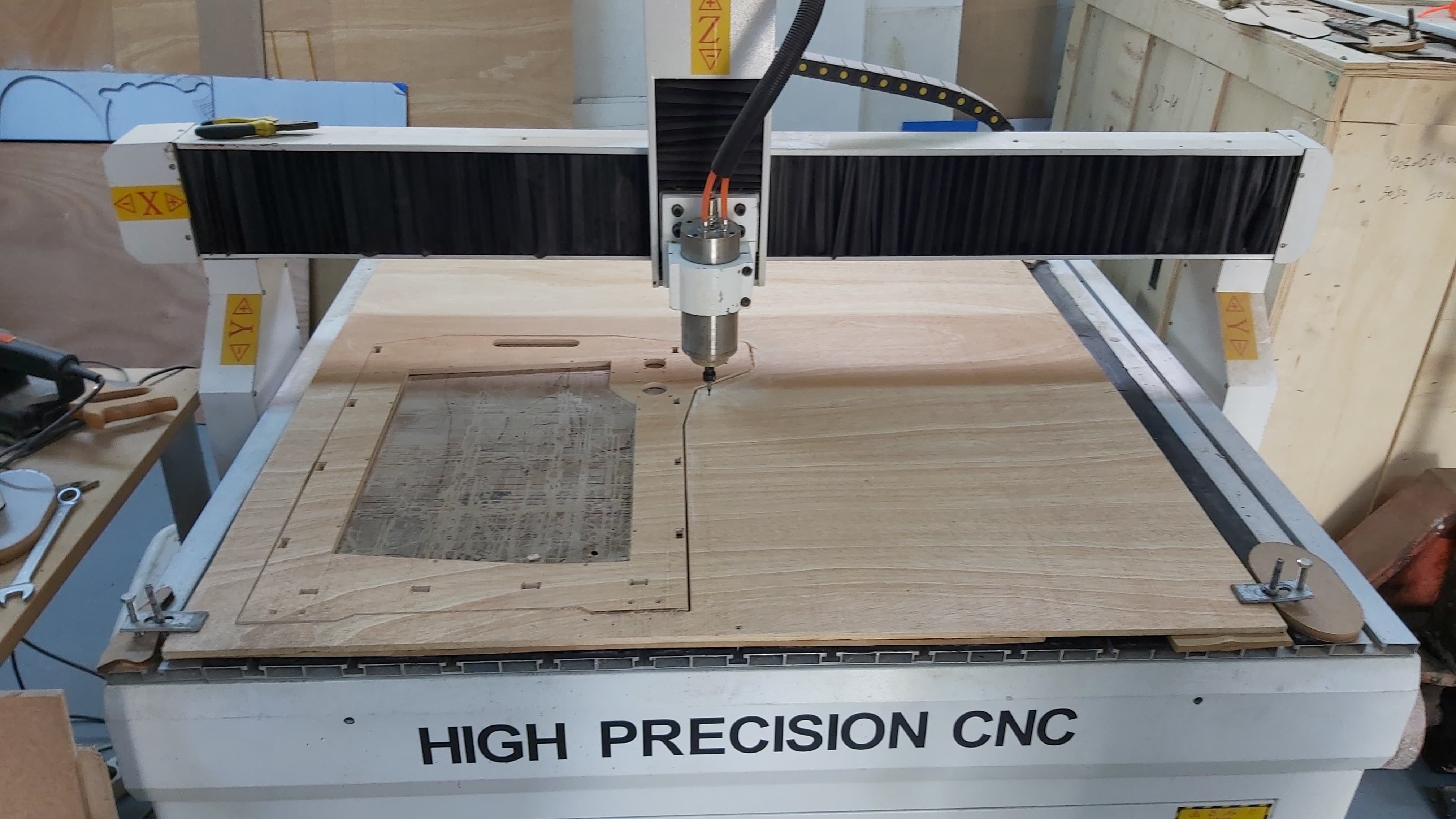
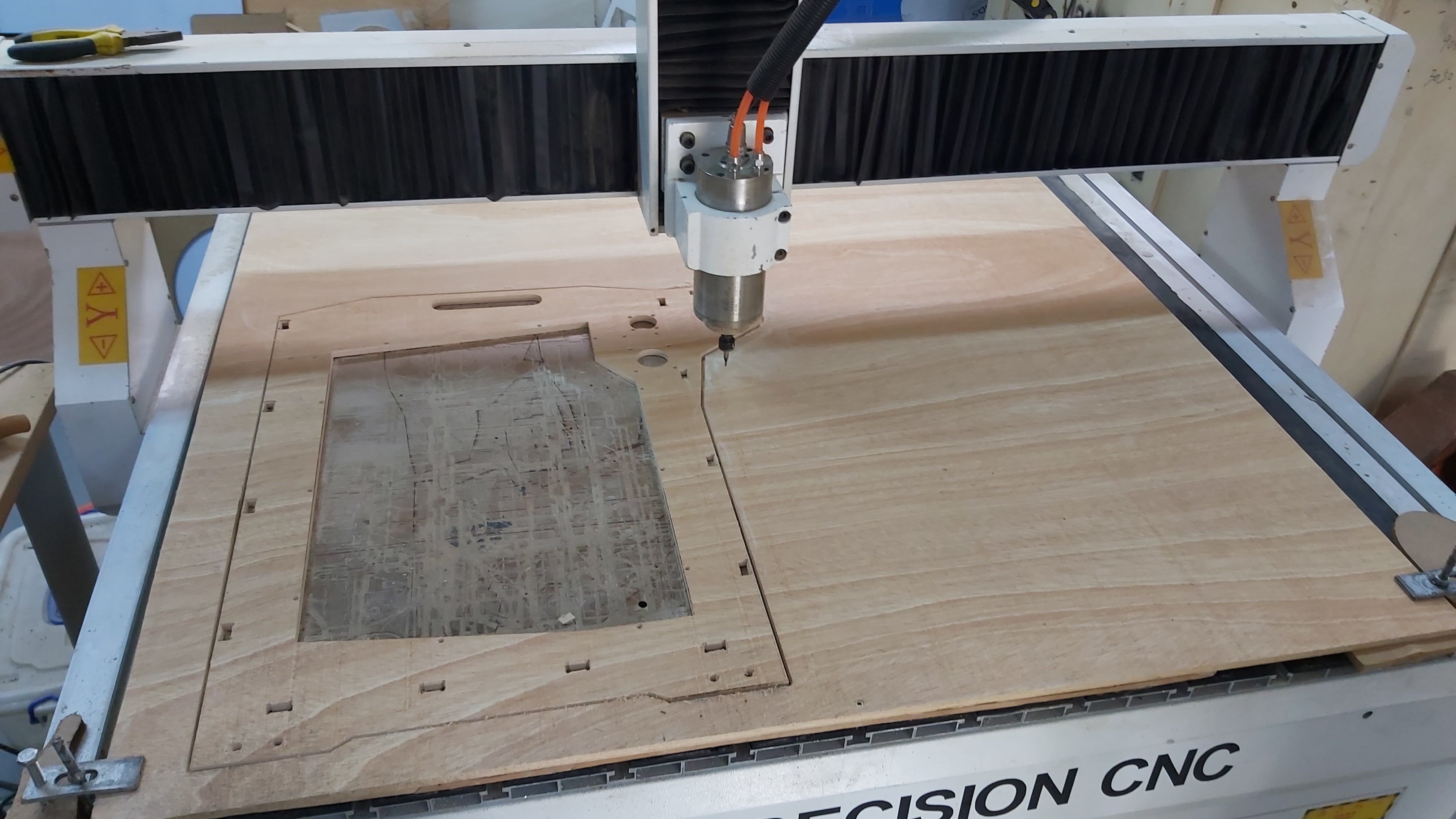
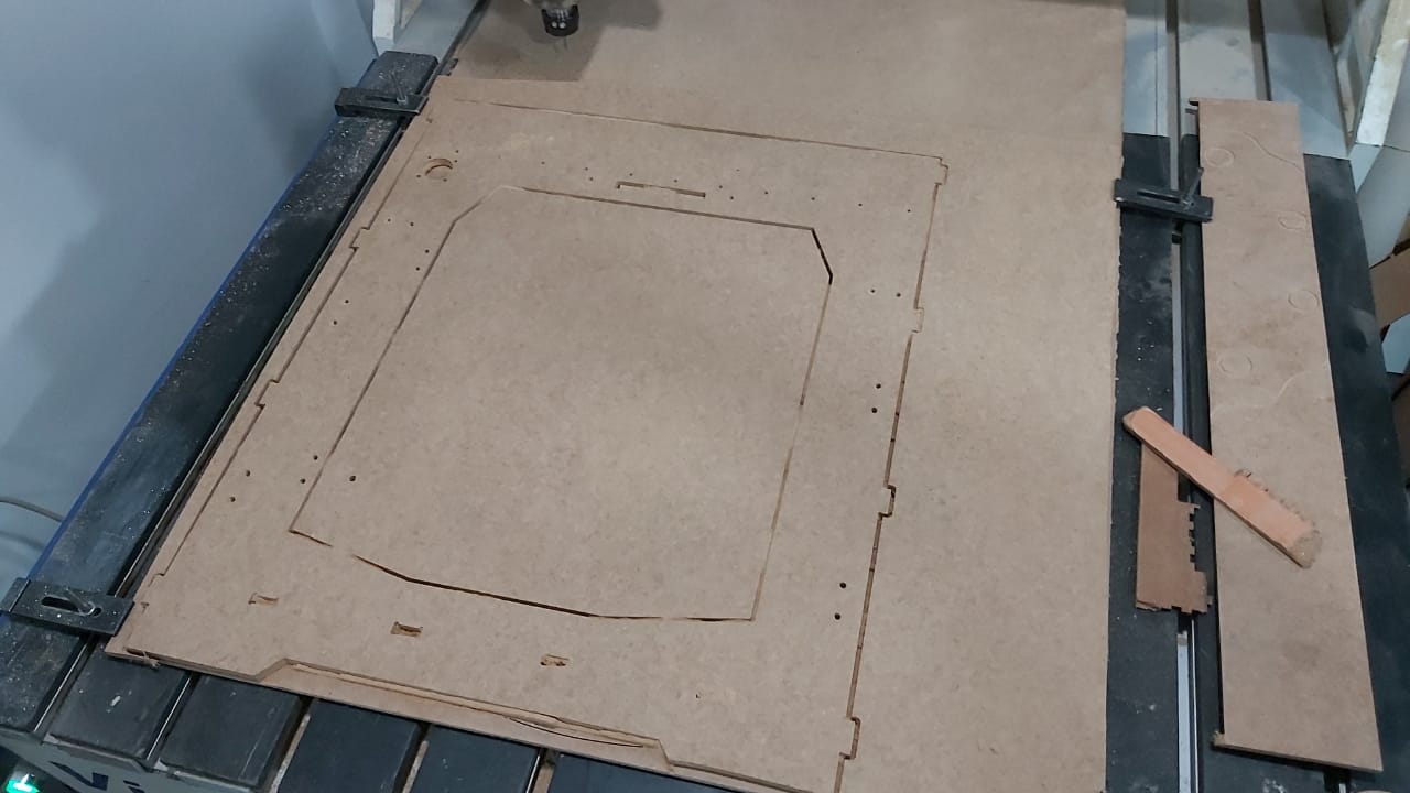
Properly, I placed the wood sheet, on the size of the default cutting plane of the machine and I took the zero Z.
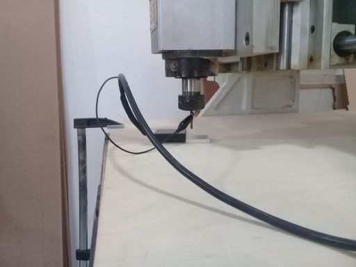
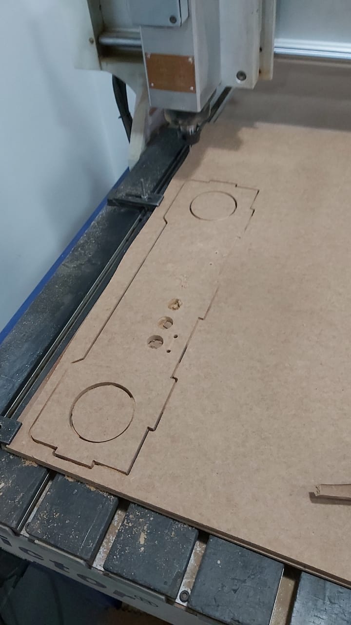
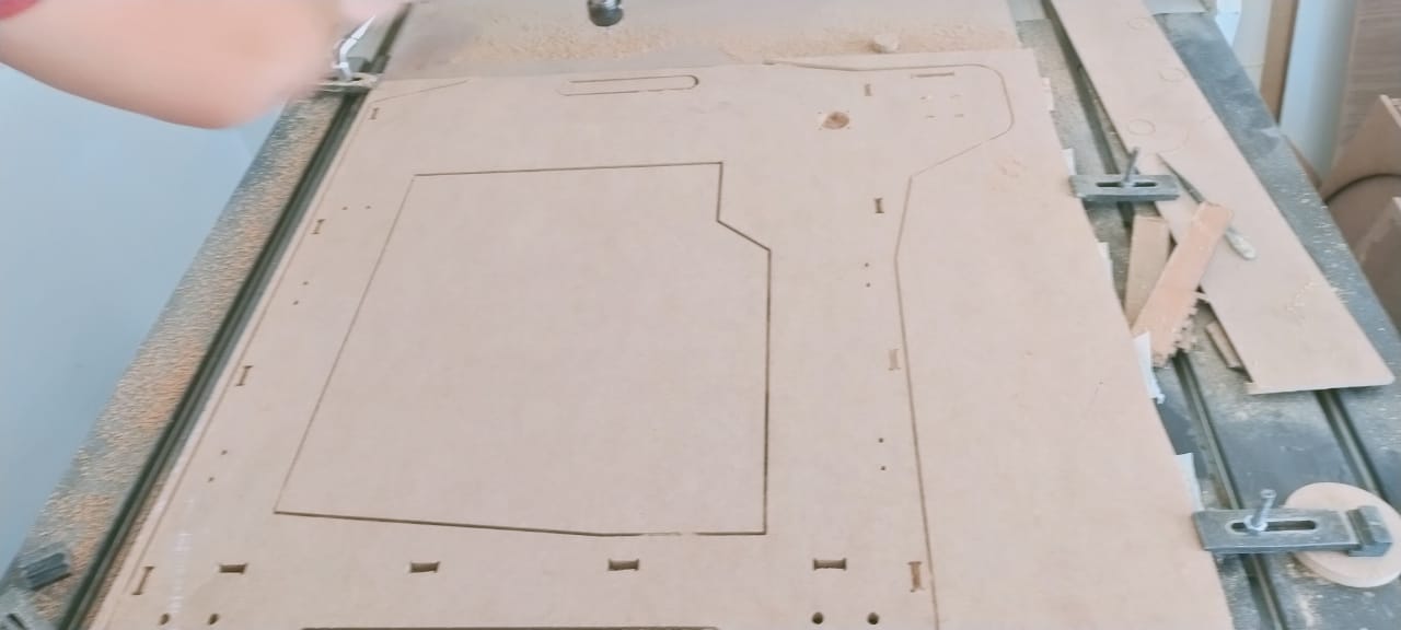
And finally I’ve started the job through by NcStudio user interface.
Result
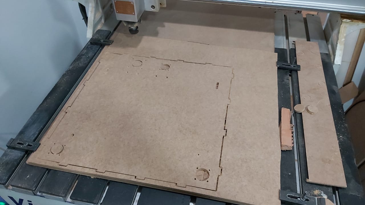
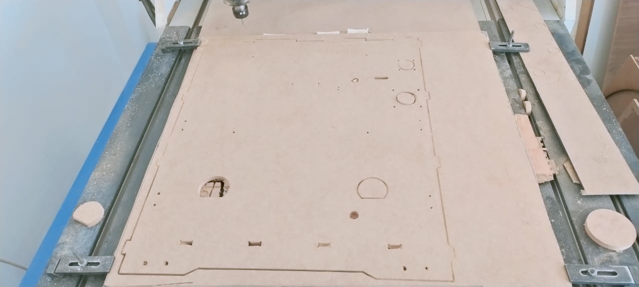
For asssembly should start with bottom assembled with the back part and then the front. After assembling these parts we can go to the sides .