3. Computer Aided design
Final Project
- Solidworks
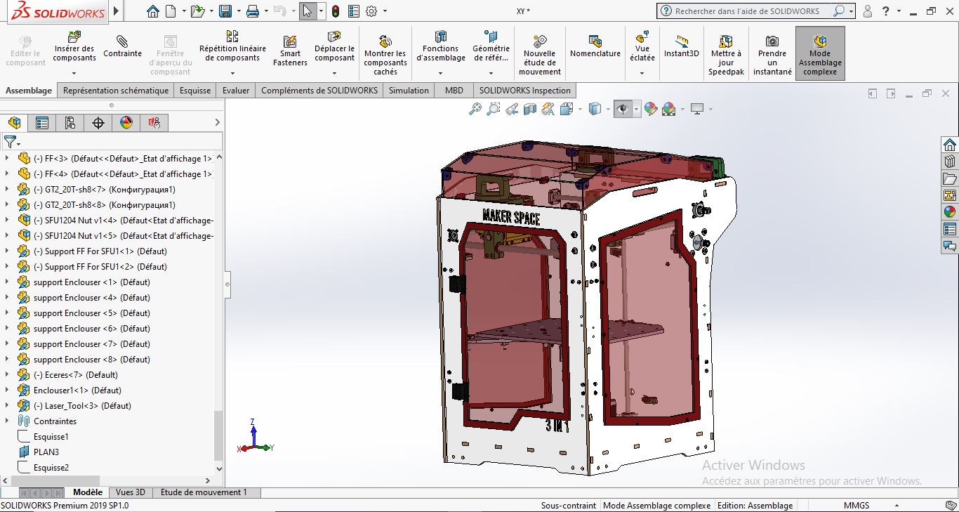
As a mechanical engineering student, I use Solidworks in my 3D Modeling and 2D skeching workflow. I started from a 3D model of a few months ago, made it entirely with solidworks.
Using Solidworks: Basics
- Getting started:
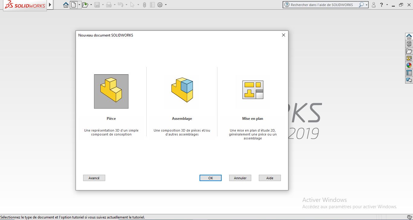
In the previous image, you can notice three diffrent modeling types:
| Type | Function | Data File |
|---|---|---|
| Part | 3D Object | *.SLDPRT |
| Assembly | Many Parts | *.SLDASM |
| Drawing | Multi-views | *.SLDDRW |
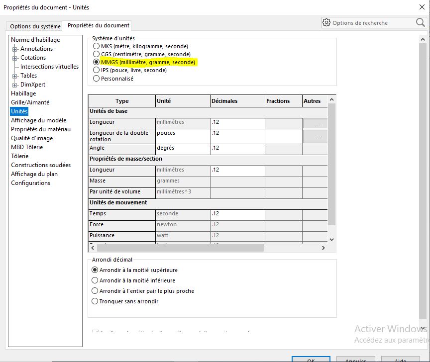
- Setting solidworks: (Only in the first time )
For the first time, you should set the document properties like the unit system and the precision tolerance.
- 3D objecting creating procedures
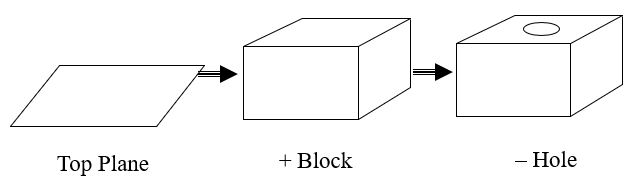
To create any 3D object, you need to create features like shown in the previous image. Each features:
-2D Sketching
-3D Formation
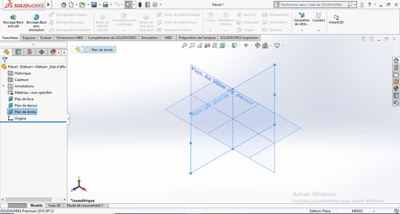
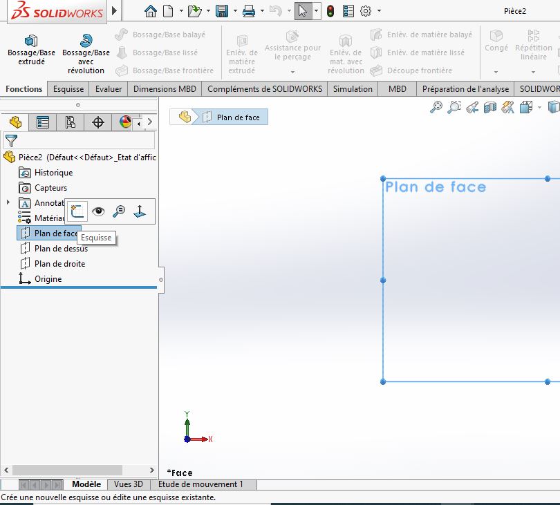
- 2D sketching:
The sketching tool is the base for any 3D model, for solidworks you need first to select a plan to start drawing on it (Front, Right or Top plan). You can also start sketching on any flat surface in an assembly and edit the sketch.
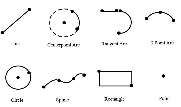
- Sketch ToolBar:

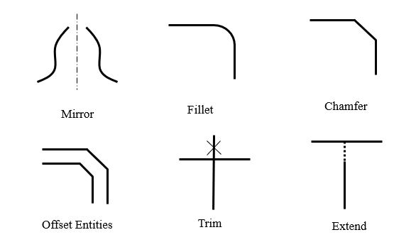
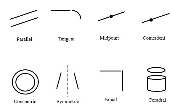
For 2D drawing there is some steps to follow, the first step is to sketch the geometry then dimension it and you will be able to modify all the dimensions, Solidworks 2D sketch works with sevral sketch entities (line, circle,Spline,…) and tools (Mirror, Offset,…). You can add some reations and mates (parallel, Concentric, …) on the sketch to make it simple with less dimensions.
Sketch entities:
Sketch Tools:
Relations & mates:
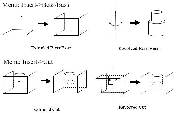
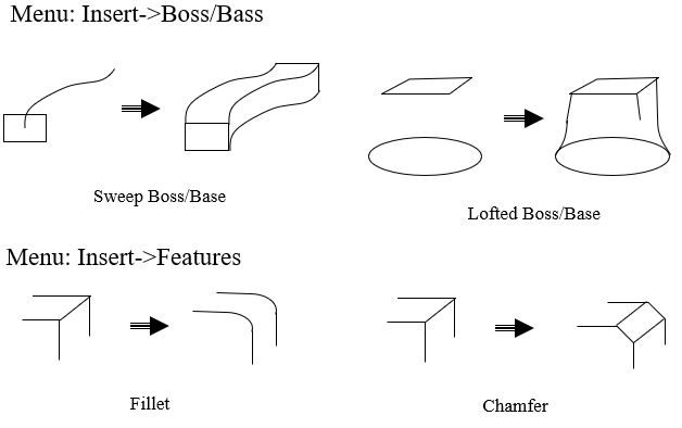
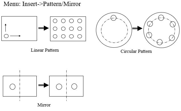
- 3D modeling:(Features)
After finishig the sketch, you just need to exit the sketch or go to functions toolbar.
These are some fuctions you can use after the sketch:
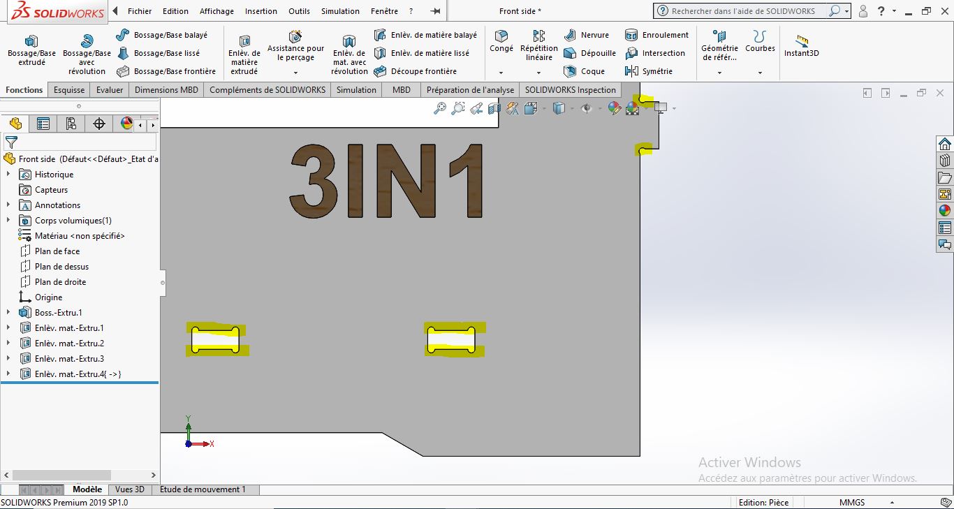
Example
1- Start a sketch on the front plane
2- Make a sketch
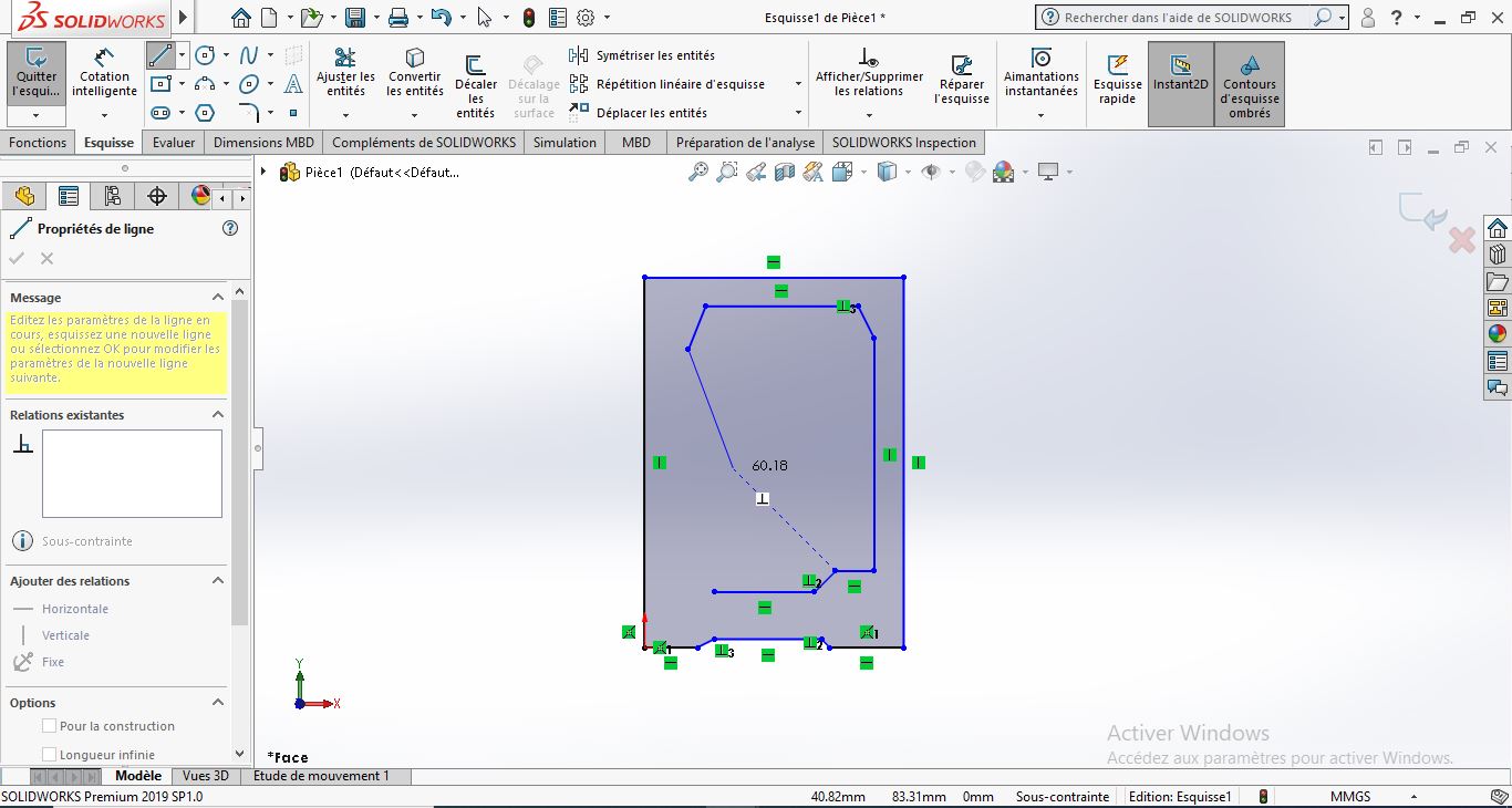
3- Add relations and dimension
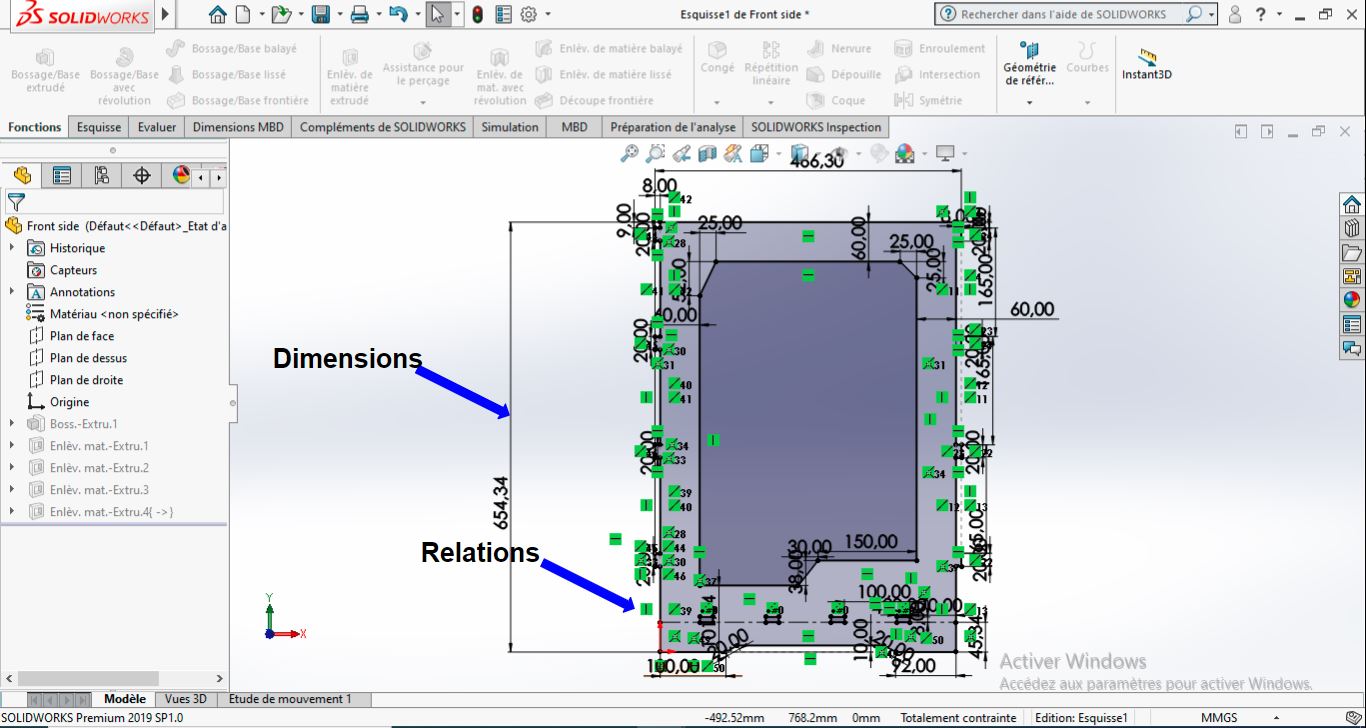
4- After completing the sketch and adding all the relation the sketch color wil be all black and then you can go to extrude function
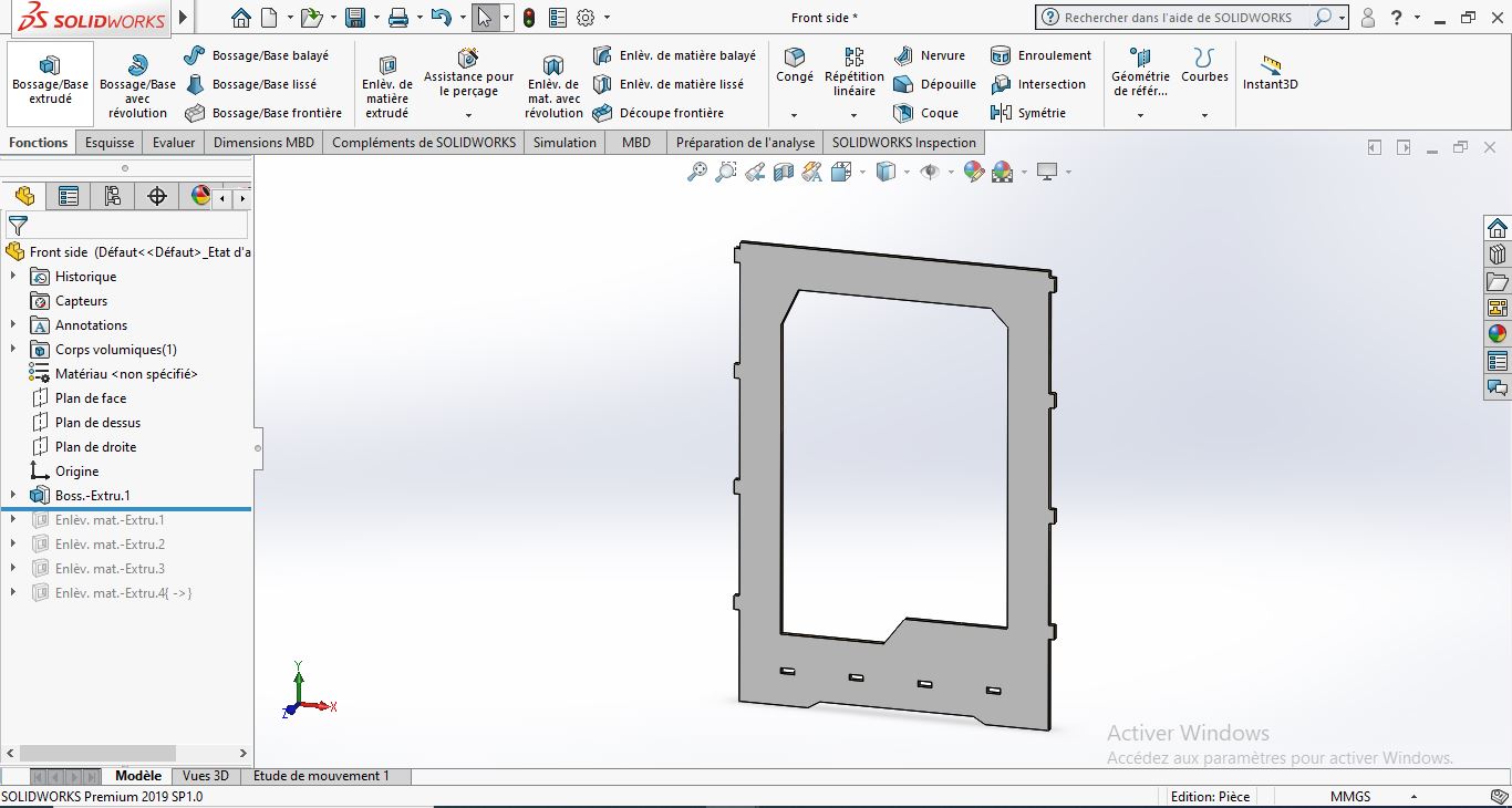
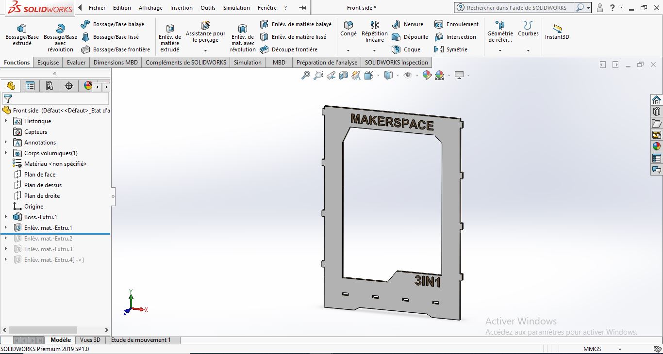
you will have this volume as a result, after that we can add the text by using the same process in sketching and then you shoul use material removal function.
- Sketch Parameter
Sketch parameter is a powerfull tool that give us the possibility to modify dinamically the model without editting the sketch from the beginig. Using Solidworks, I will present how to add parameters
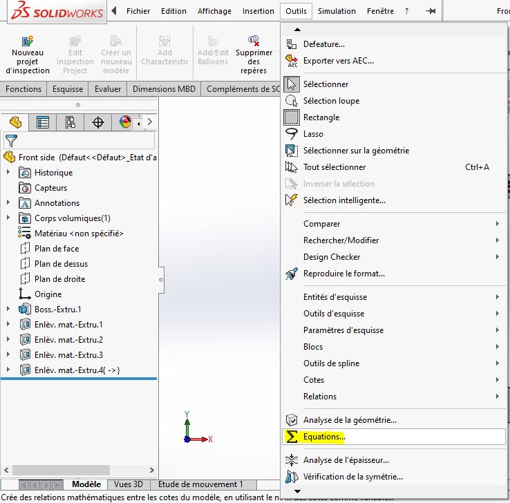
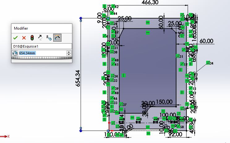
Step 1: Go to tools and choose Equations
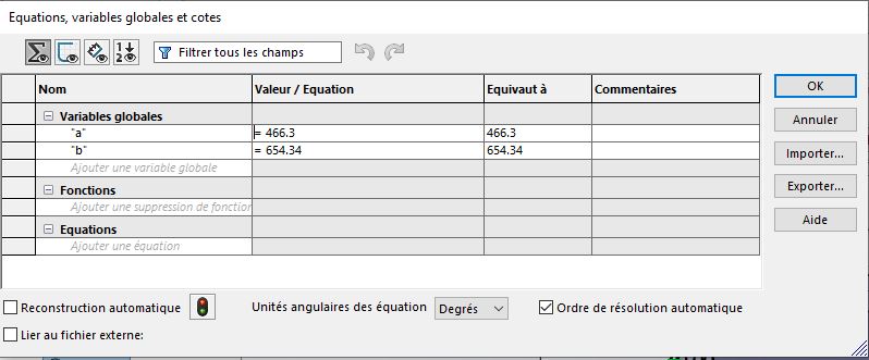
The following window will appear. After that enter the parameters you want, and press ok:
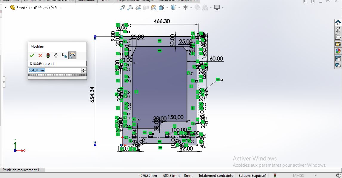
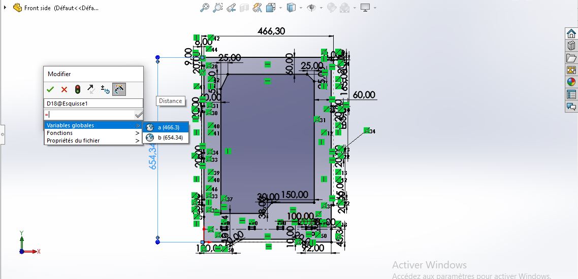
You should use the parameters during the sketching proccess and enter them when you are using the dimensionning tool: just press ‘=’ and then choose the correct parameter.
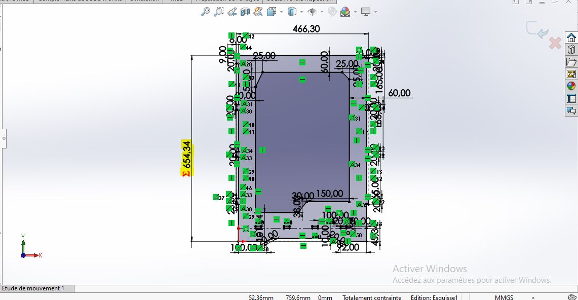
Exit the sketch and you will find your parameters in feater manager under Equations folder:
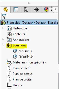
you can now modify the model using directly the parameters in Equations folder. (without editing the sketch)
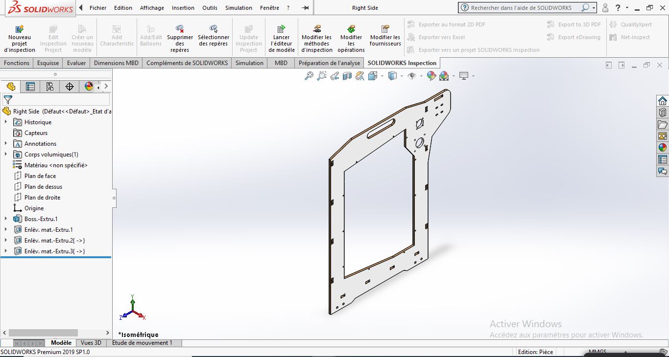
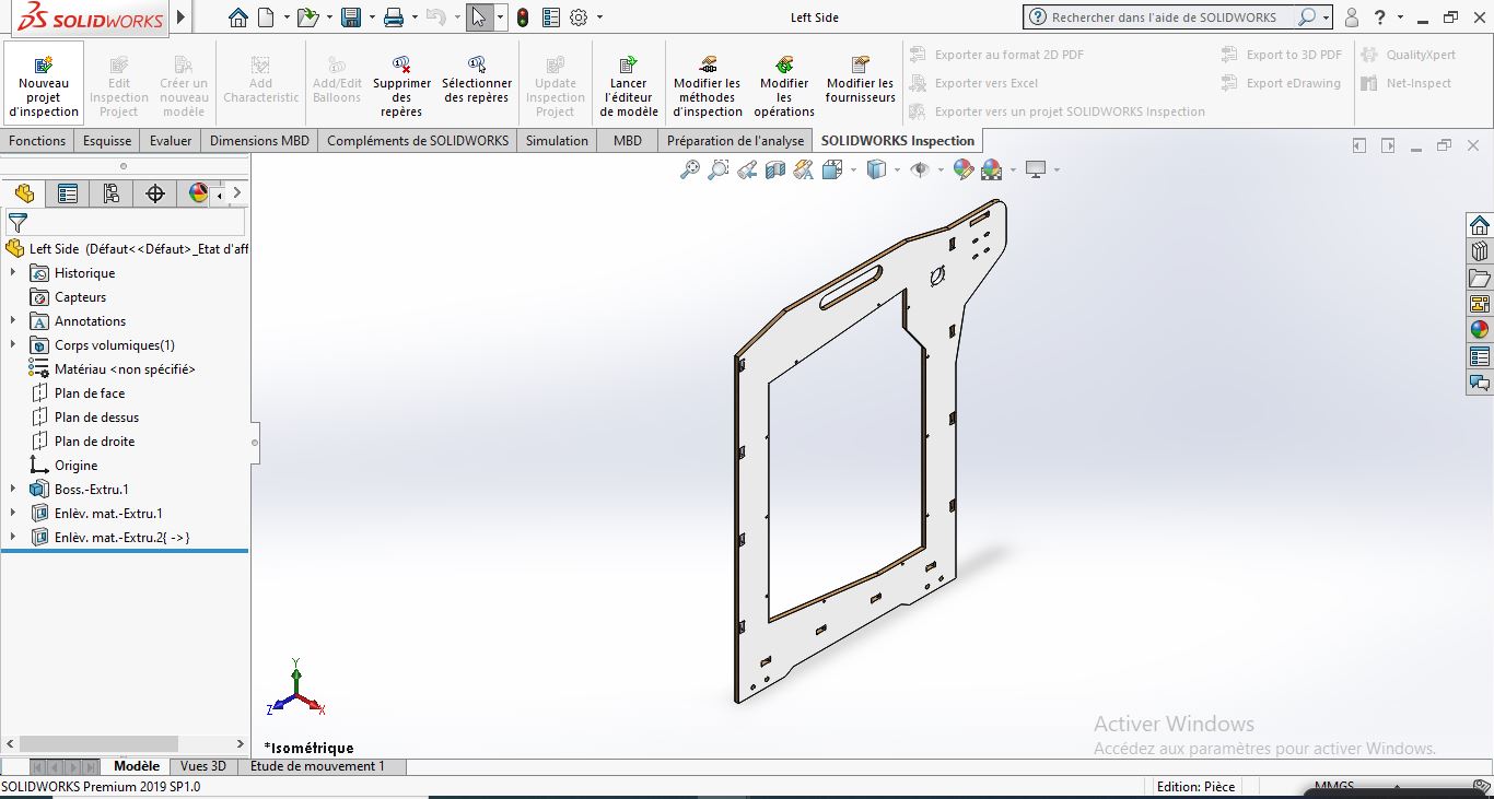
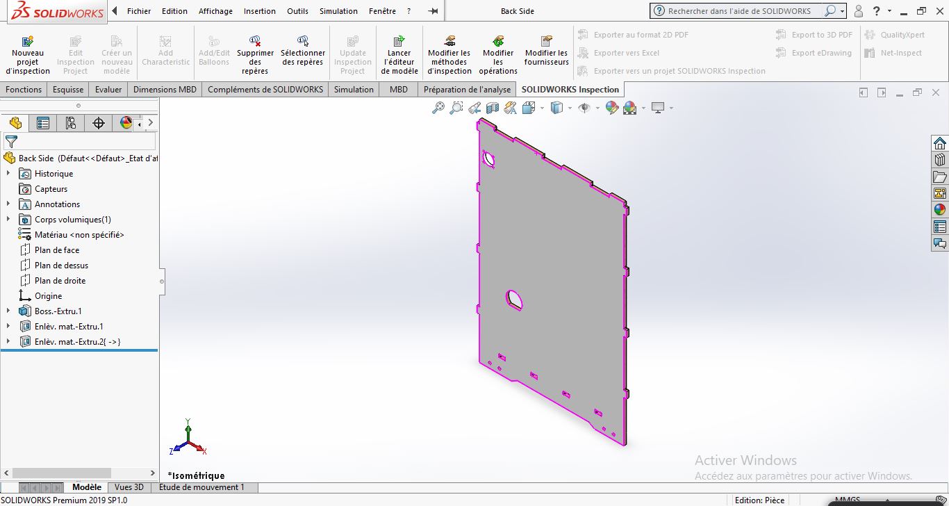
The frame of the machine will be made using a CNC machine, after doing some researchs aboout CNC cutting I found that the machine has some limits like not having 90° angle.
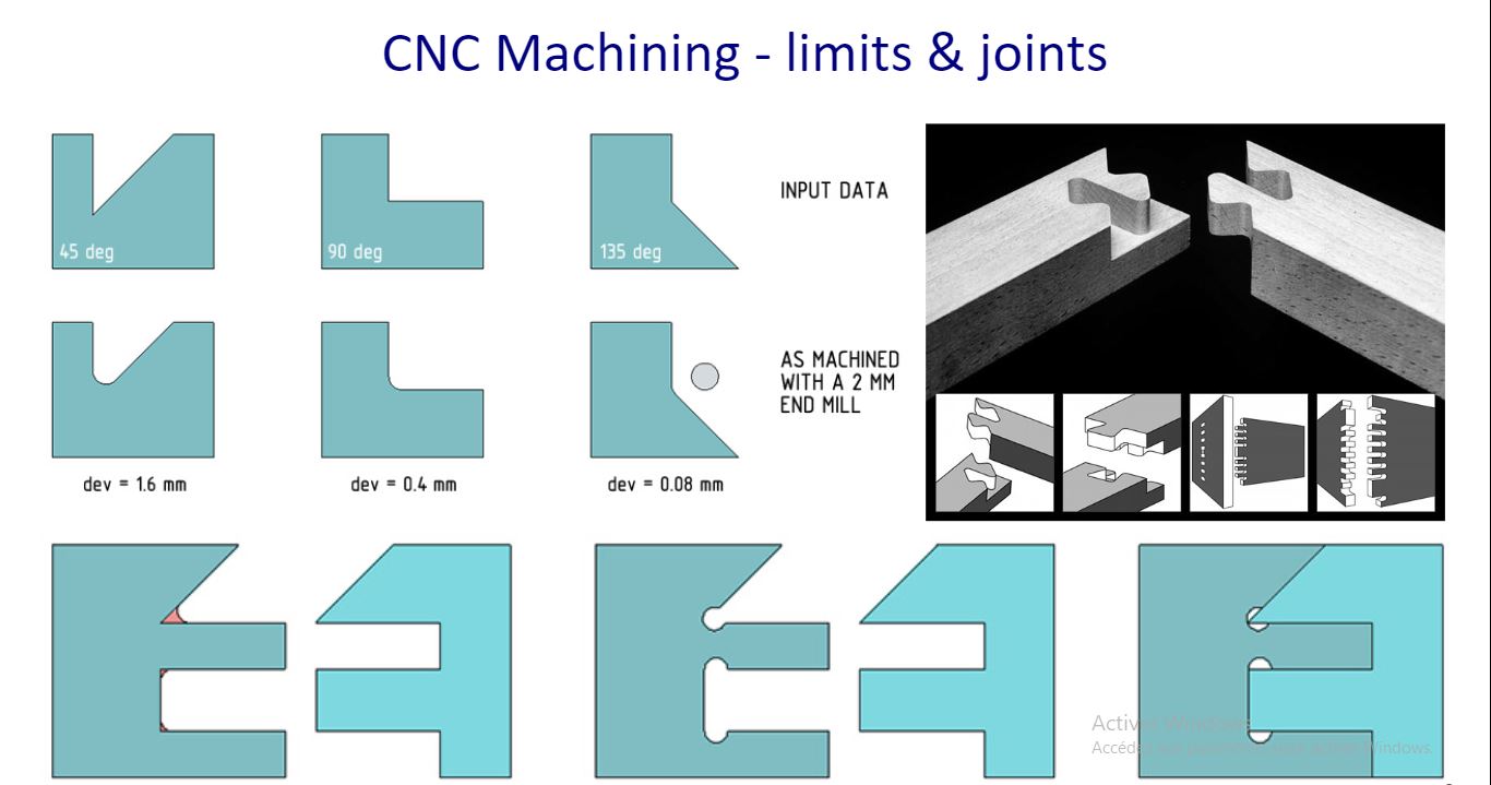
So to solve this problem, I added the tool diameter in each 90° angel:
I did the same steps for the rest sides of the machines.
Solidwork Assembly
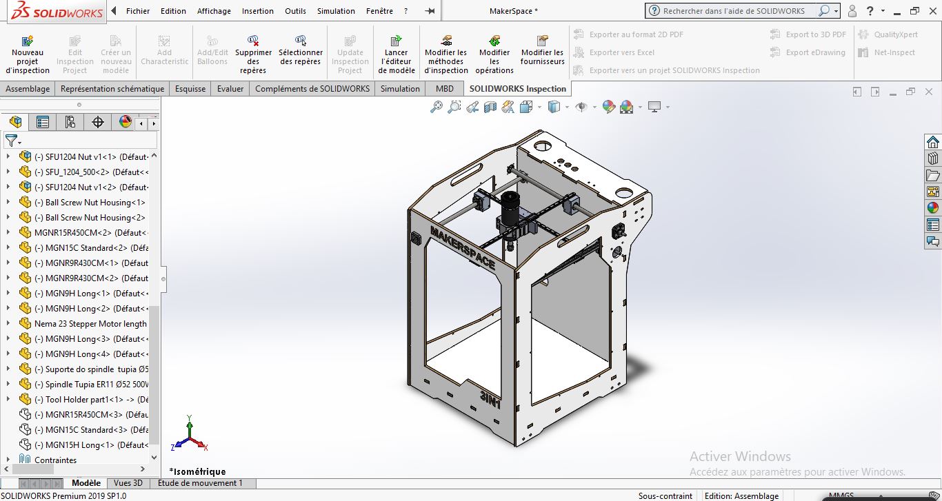
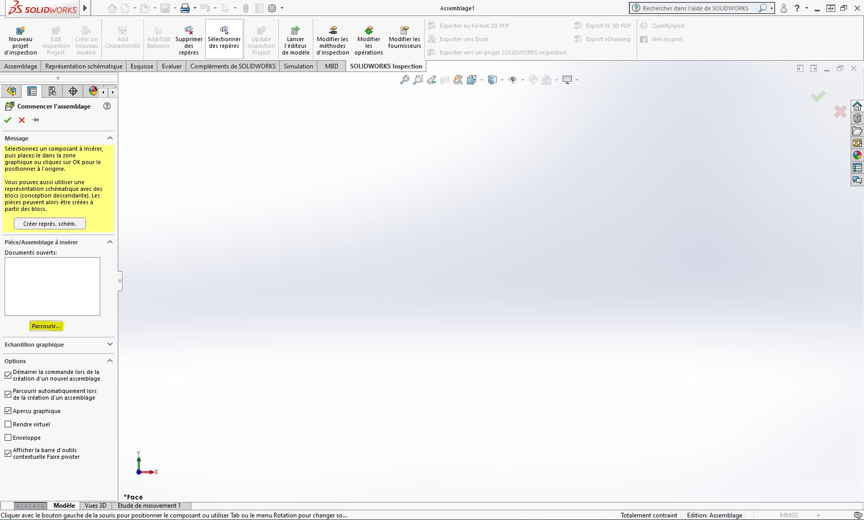
I prefer always using Solidworks for assemblies; specially for machine design. To start the assmebly, you should first start new assembly file, the “insert components” tool will be activated automaticaly in the begining where you should insert the parts you designed.
Note: Solidworks assmebly can support many 3D files format like (STEP, IPT, Catia,…)
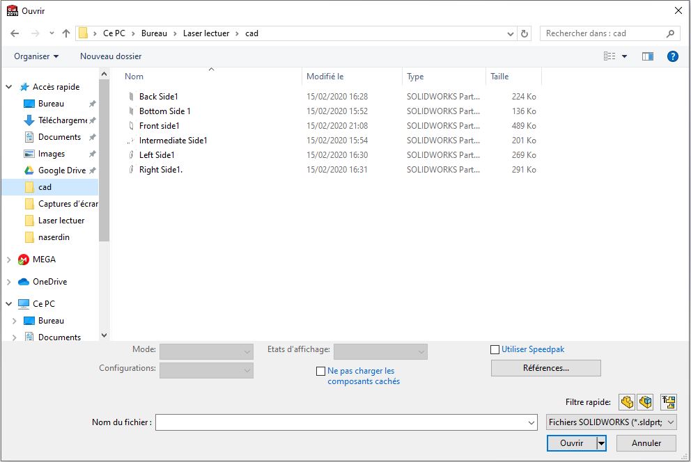
To import a 3D file you can use also the tool bar in solidworks

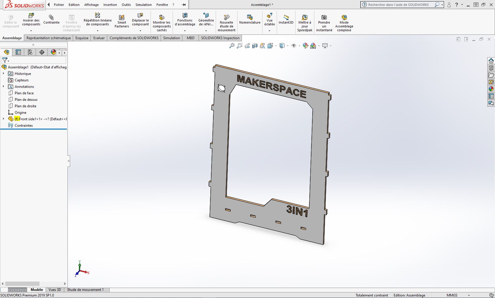
The first file you upload in your assembly will be fixed automatically in the workspace and an “(f)” sign will appear in the Features Manager.
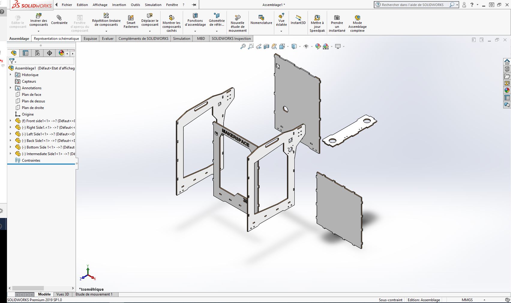
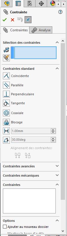
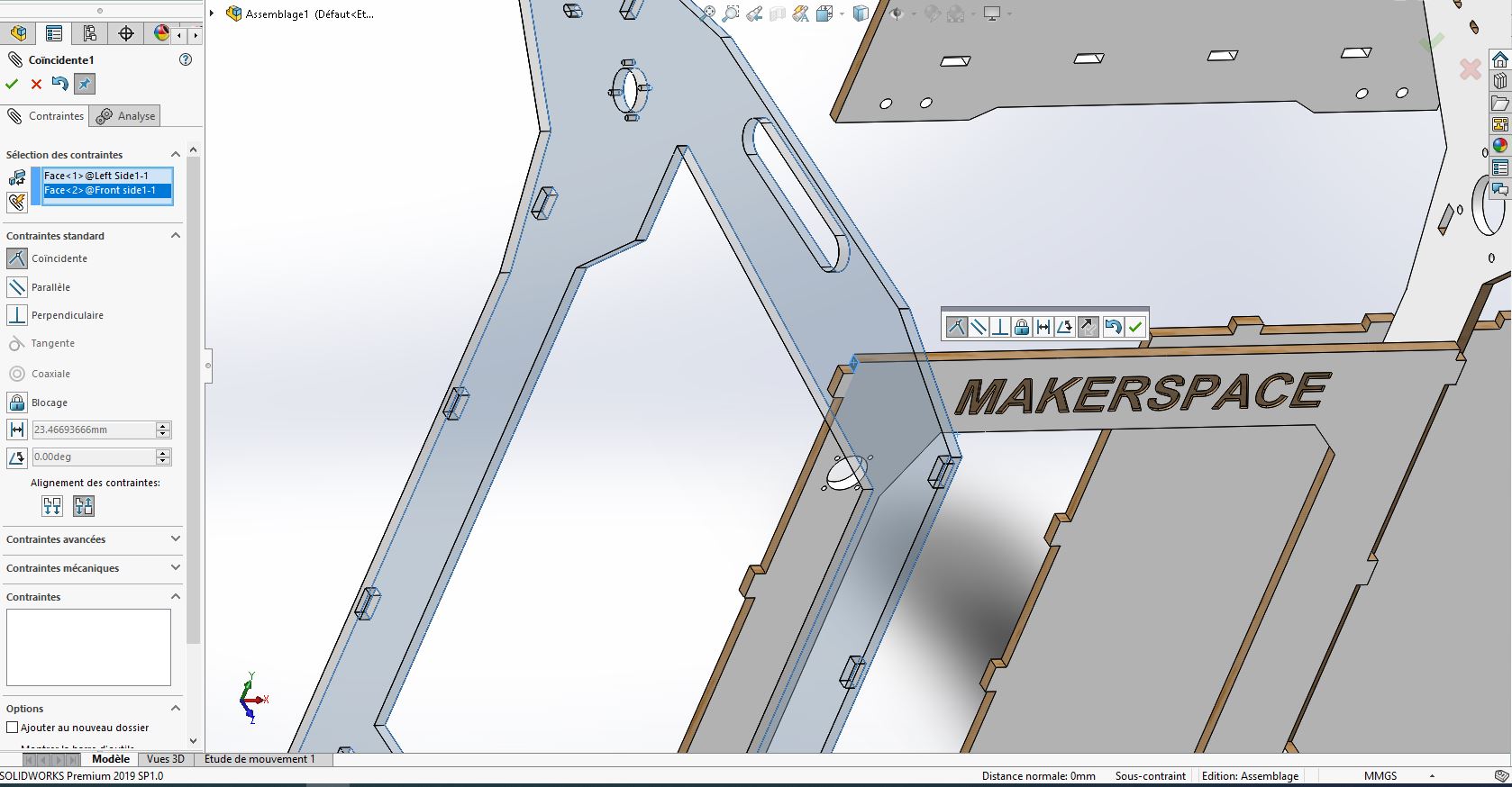
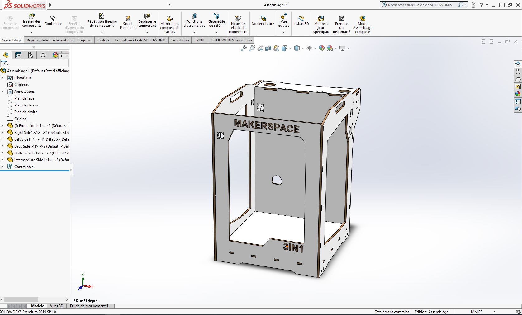
After uploading all the parts in the workspace we can start joining all of them using mates and contraints.
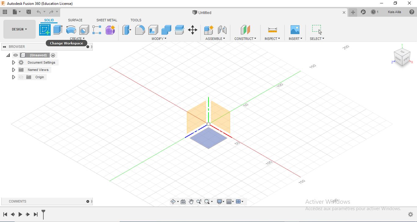
2D Sketch
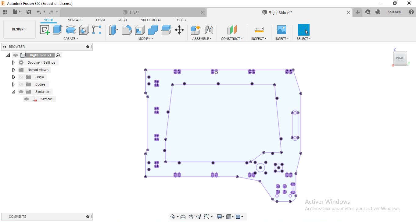
Fusion 360 is a very good tool and easy to use for 2D sketching and 3D modeling after, I will be using it for 2D sketc. The sketch is easily accomplished in the “Sketch” tab, by selecting the necessary tool to work with and then select the plan to sketch
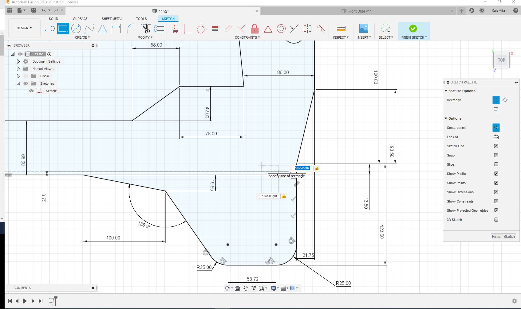
we will create a 2D sketch for the right side of the machine by choosing the right tool and indicating the right sizes and of course adding relations and mates to the sketch
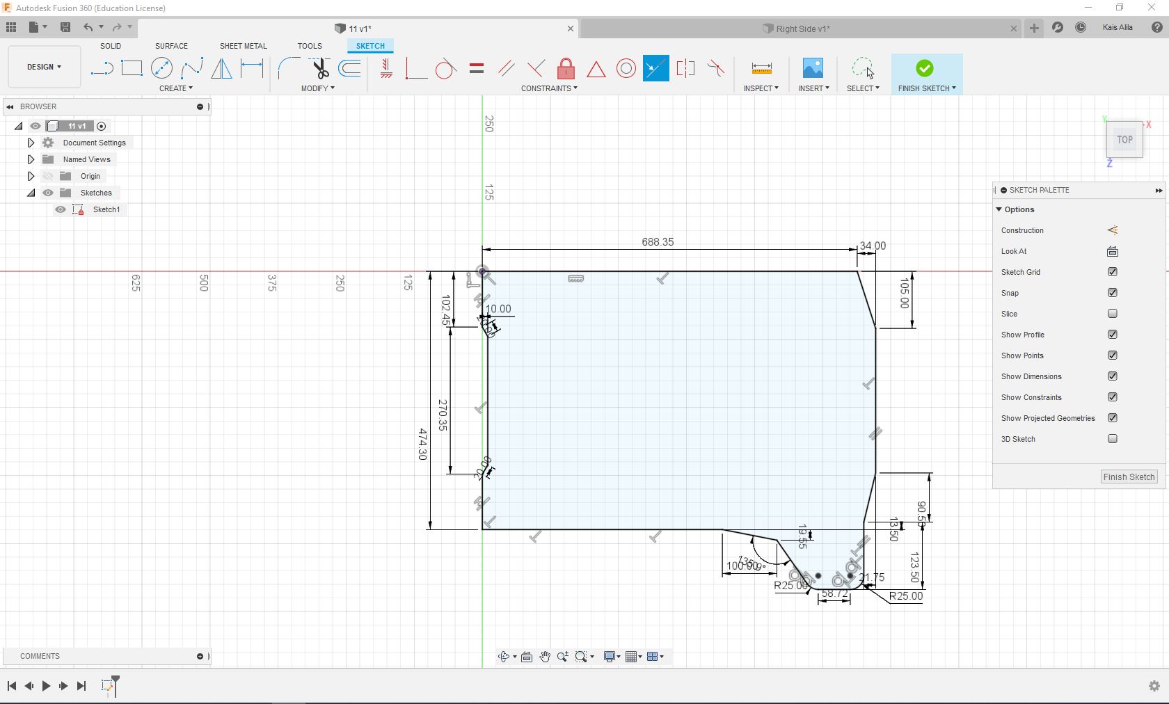
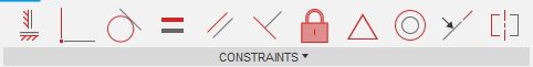
By using the constraints in the Sketch Palette we can easily constraint our design lines to have a behaviour. This comes handy in designing crytical measurements, adjacent, parallel, perpendicular lines and so on.
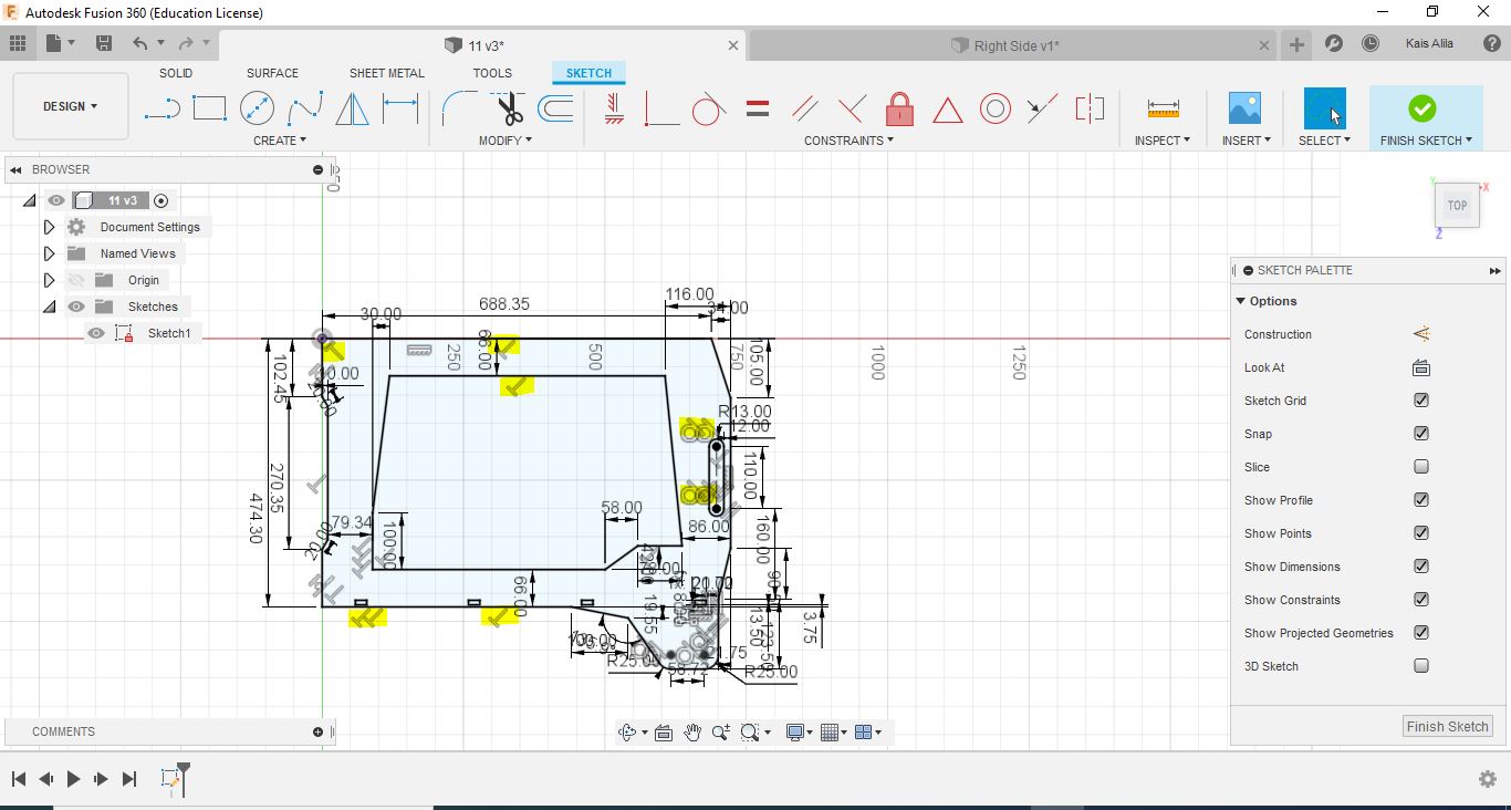
We can also use fusion in parametric design, the frame was designed to be assembled like puzzle so I added some parameters on the frame. The first step was to add parameters:
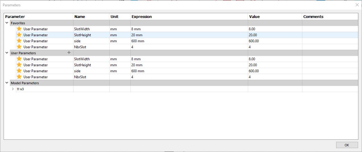
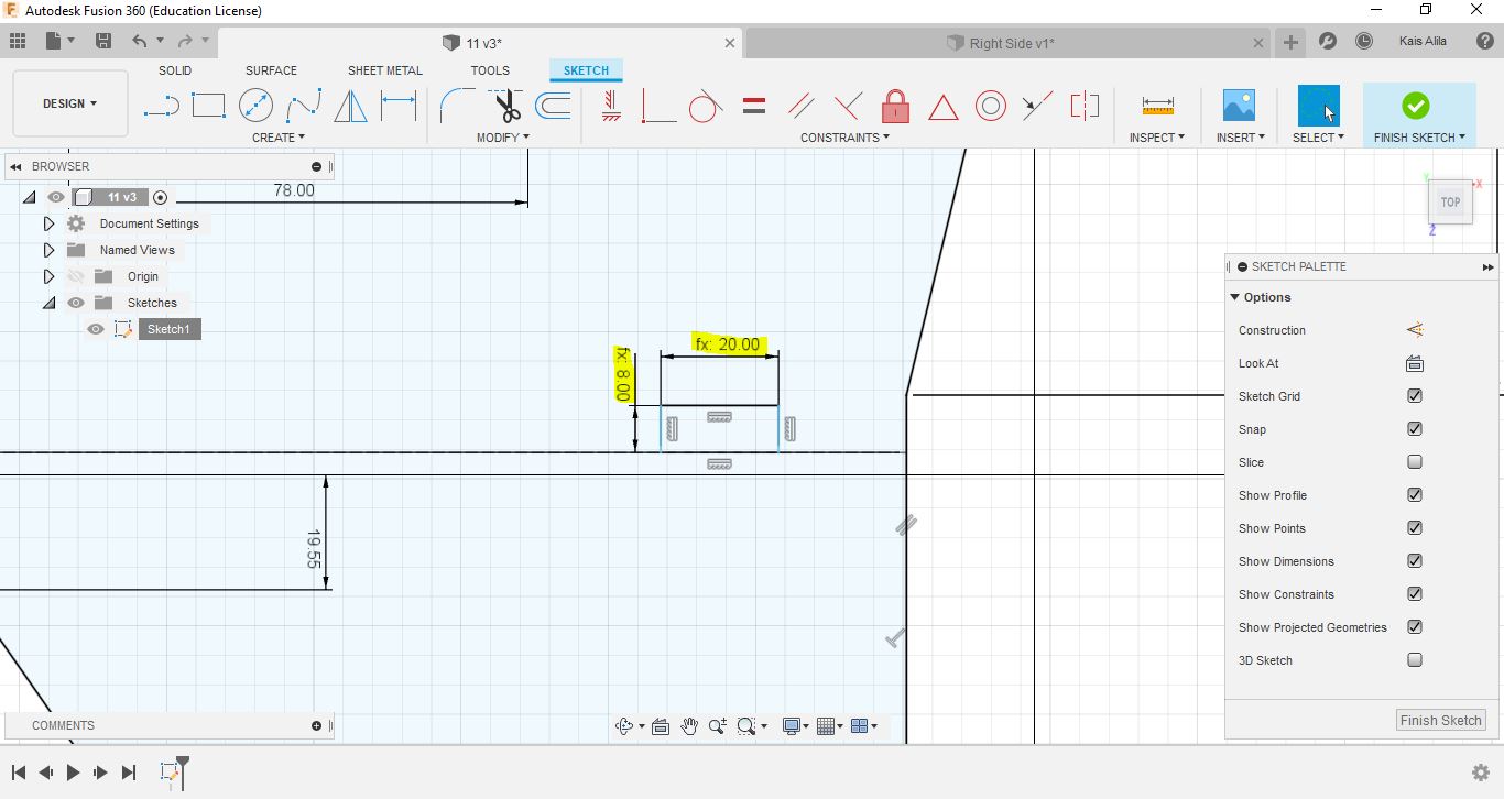
The sign “(fx:)” will appear, this means that you can modify the model after without editing the sketch.
To make the slots faster I used Rectangular pattern tool
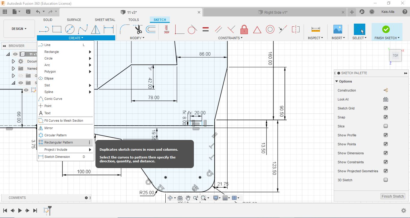
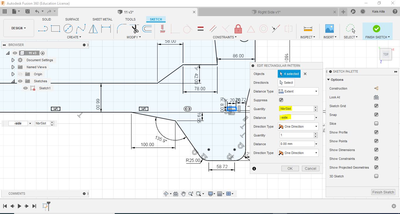
and thats the final result.
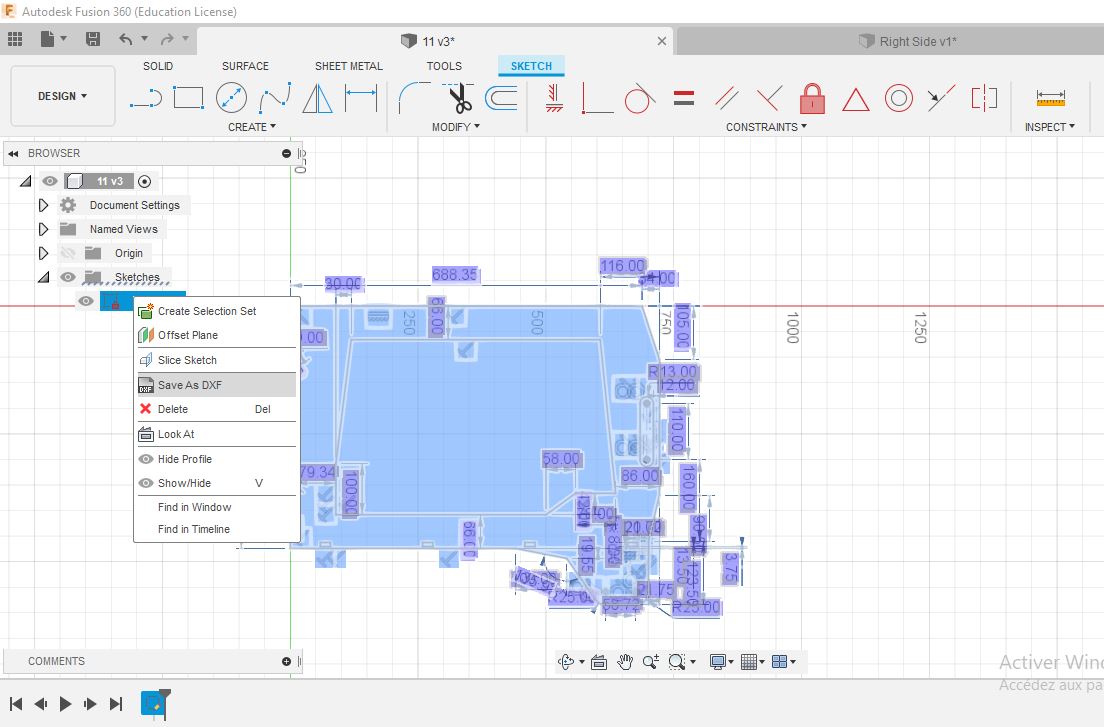
We can use this sketch for laser cutting or cnc after exporting to DXF format.
Simulation
For my machine, I used Solidworks simulation to study the displacment of the rails in order to choose the best rail dimension for the system. In the following images, I applied a 500N force on the both rails and the software solved the problem of the displacment and give an approximative result of the deforming . I chose MGN15 for the machine based on these results.
Render Keyshot v9
Thanks KeyShotVR I’ve made a photorealistic, touch-enabled, 3D rendered image, wich can be displayed in every web browser supporting HTML5.
Note: The content below can be viewed by using mouse or finger on touch-enabled devices and does not require a browser plugin to work. Furthermore, KeyShotVR is not WebGL based and is therefore able to deliver the highest quality possible across the widest range of devices.