7. Electronics design
This week I worked on defining my final project idea and started to getting used to the documentation process.
Here is the link for the groupe assignment page
Hello Board
For this assaingnment, I should redraw the echo hello-world board adding a button switch and a LED based on Neil’s echo hello-world board so I will need these components to start with:
| Qty | Value | Device | Package | Parts |
| 1 | 6MM_SWITCH6MM_SWITCH | 6MM_SWITCH | S1 | |
| 1 | LED1206 | 1206 | LED | |
| 1 | 100k | RESISTOR1206 | 1206 | R1 |
| 2 | 10k | RESISTOR1206 | 1206 | R2, R3 |
| 1 | 16Mhz | CSM-7X-DU | CSM-7X-DU | Q1 |
| 1 | 1uF | UNPOLARIZED_CAPACITOR1206 | 1206 | C3 |
| 1 | 22pF | UNPOLARIZED_CAPACITOR1206 | 1206 | C1 |
| 1 | 22pf | UNPOLARIZED_CAPACITOR1206 | 1206 | C2 |
| 1 | ATTINY44-SSU | ATTINY44-SSU | SOIC14 | IC1 |
| 1 | AVRISPSMD | AVRISPSMD | 2X03SMD | U$1 |
| 1 | FTDI-SMD-HEADER | FTDI-SMD-HEADER | 1X06SMD | FTDI |
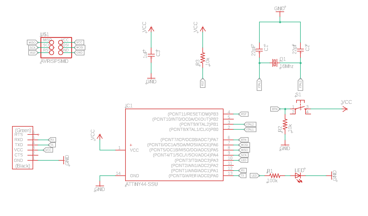
Schematic
I am used to work with ISIS software to do the schematic of the electronic board and then use the extension ARES to design the board. Now after the lecture with my instructor I chose Eagle as Electronics design software tool to write my Scheme and design my Board.*
Based on ATtiny44-84 datasheet I’ve choose to use PIN7 Analog Input for Button as and PIN3 as PWM for LED.

These are the steps to design:
-
Open new project & then Create new .SCH (schema) file
-
Add the necessary library to find the components
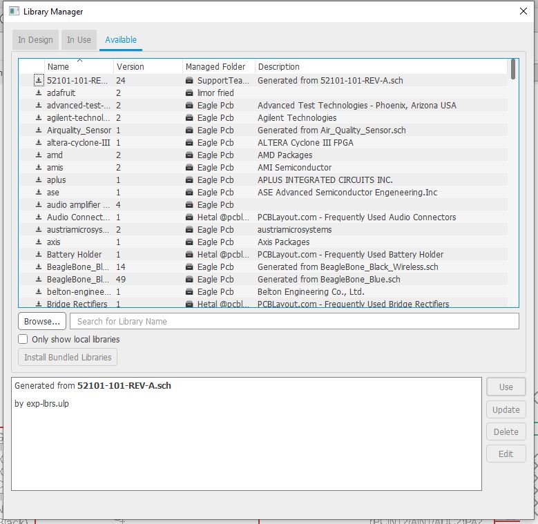
- from Edit/Add… add all the components I need in the scheme canvas and remember to give they a $VALUE use $NAME to create connections
Work :
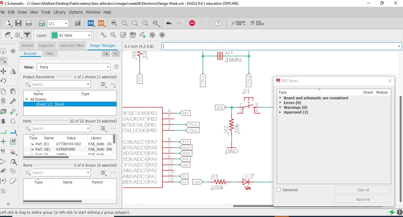
To check my schematics I use eagle feature ERC. This is a handy little tool that you’ll always want to keep in your engineering toolbox, as it helps to point out common errors in your schematic. An ERC will check for the following issues:
-
Are all of your nets properly connected and labeled on your schematic?
-
Do you have any conflicting outputs/inputs on your schematic?
-
Are there any open or overlapping pins and ports on your schematic?
You can think of an ERC as a second pair of eyes; it will always be there to help you find the missing details that you may have overlooked! Of course, an ERC is not meant to be a replacement for reviewing your schematic manually, so don’t rely on it as your first level of defense.
Types of ERC Errors:
Consistency Errors: consistency-error This error means that something isn’t right between your schematic and PCB layout, and your changes likely aren’t in sync between both files. If you get one of these errors, consider it a major red flag to compare both versions of your design before moving ahead.
Errors: error Errors are the red stoplights. You need to step on the breaks and check these out before proceeding. Errors can be pretty significant, like having an unconnected pin that will throw your whole circuit out of whack.
Warnings: warning Warnings are the yellow stoplights. While these types of errors might not mess up your design if you move forward without fixing them, it’s good practice to slow down and review them one by one. These guys are minor compared to Errors, and n include many non-design breaking issues like missing net values.
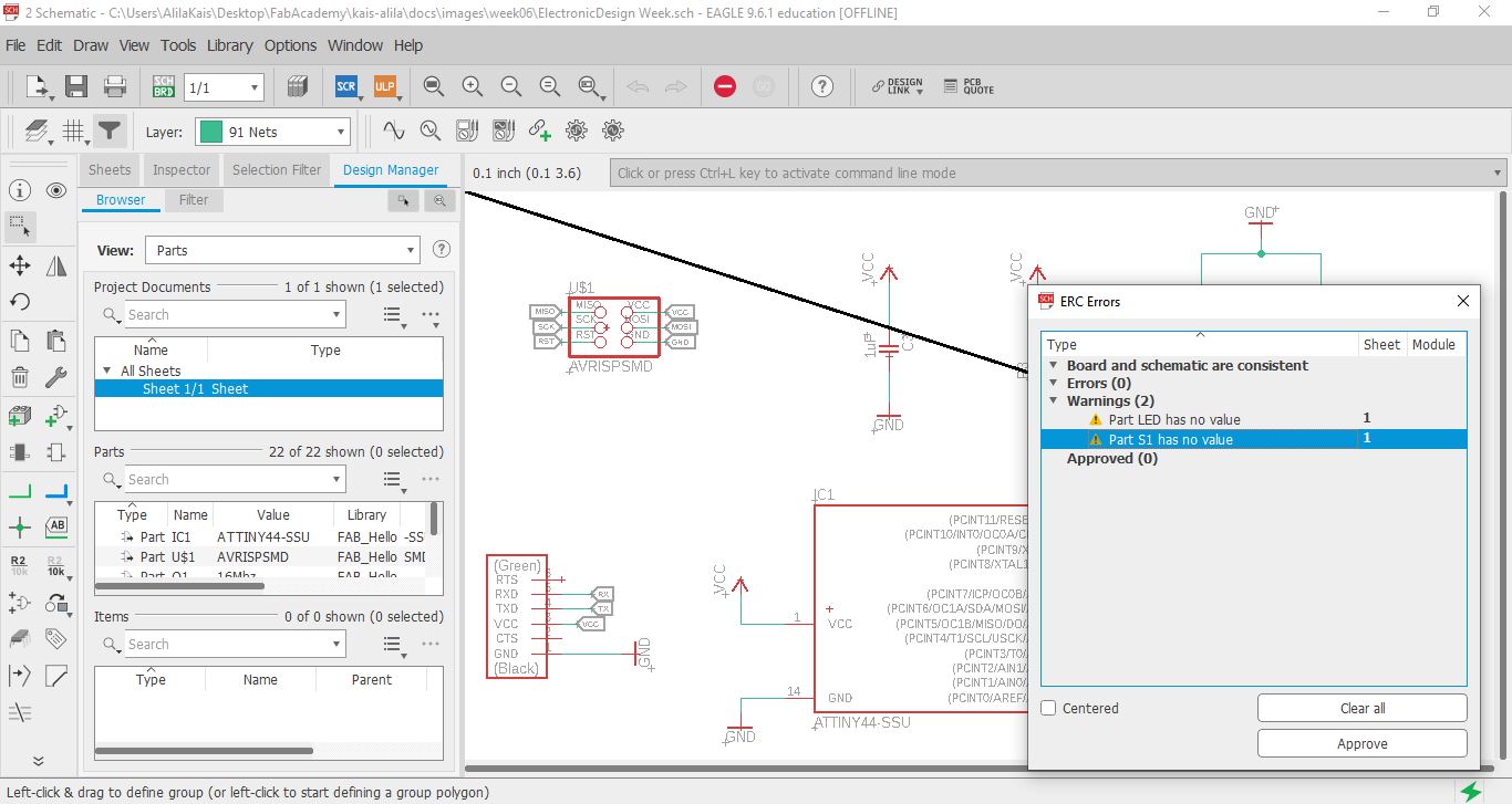
The image shows us that we have some warnings and some wwires has no name or no value for some components then we can approve it after fixing it.
## Board
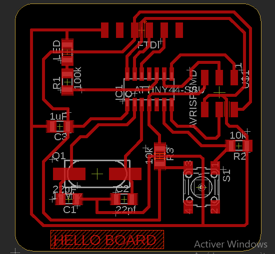
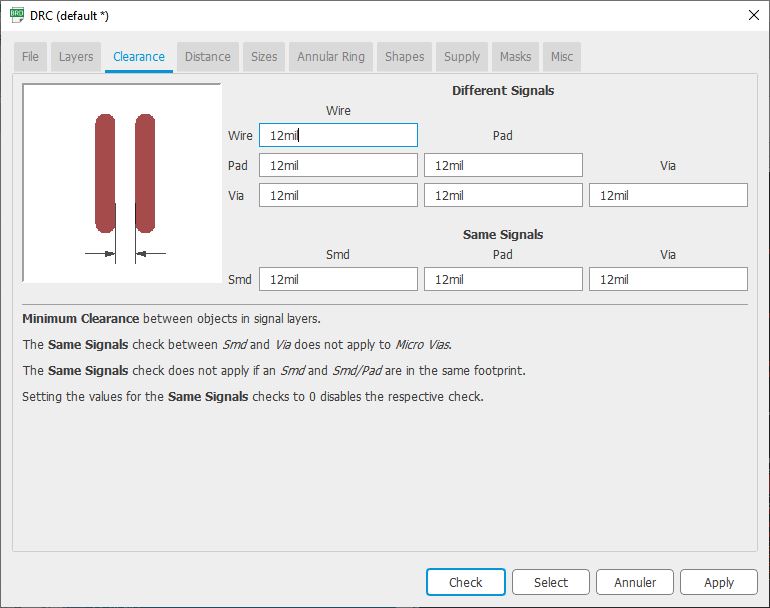
To check my board and make it machinable using the cnc of our fablab, I checked the clearance and every detail of my borad using Eagle design rules: DRC . Using our CNC and the tools availble for now in our fablab, we are able to make 12mil as clearce to have a good quality board as shown in this image.
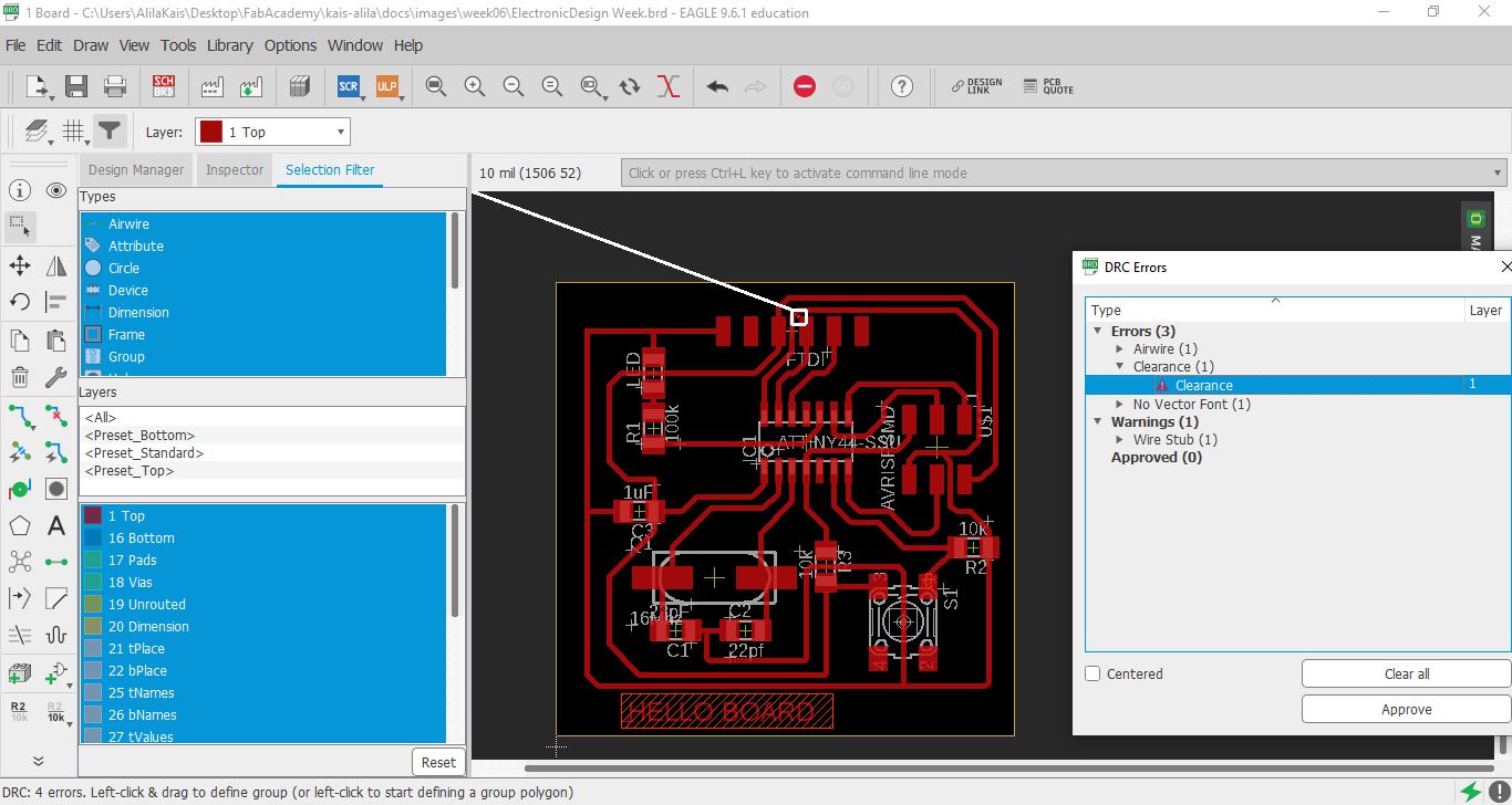
As shown here, the DRC here shows us that we have one airwire to fix and one clearance
Download Files: Hello Board: Schematics, Hello Board: Board
## Milling
Same setting and steps shown in week 5 i did the same process to generate the gcode to the machine
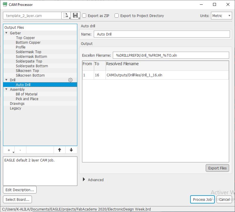
- Step 1: FlatCAM Reads only gerber file for the trace and for the outlines, exported from the desing software like EAGLE, ad it also supports drill files like XLN alo exported from EAGLE. EAGLE is a powrfull software that uses a CAM Processor to export all the needed layers and jobs for a complete board.
a. After desinging the board you should open CAM Processor tool for EAGLE to export the needed files for FlatCAM.
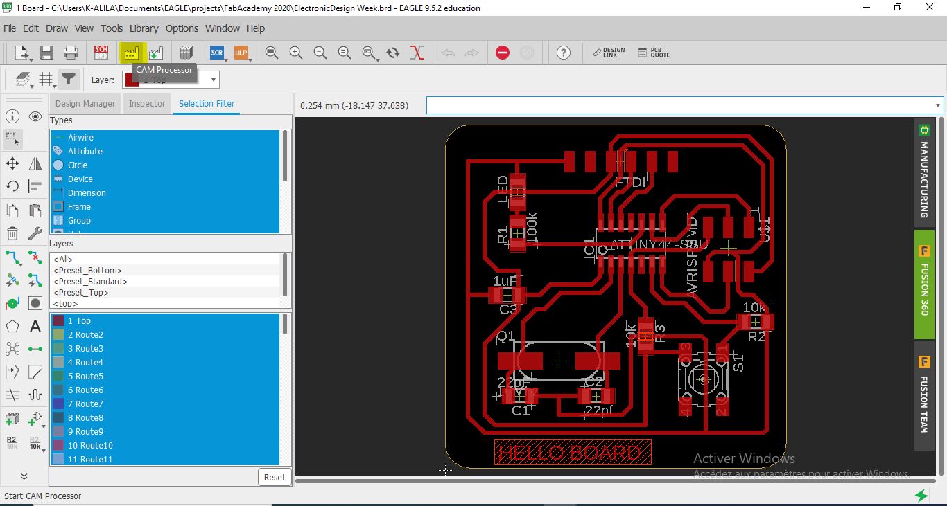
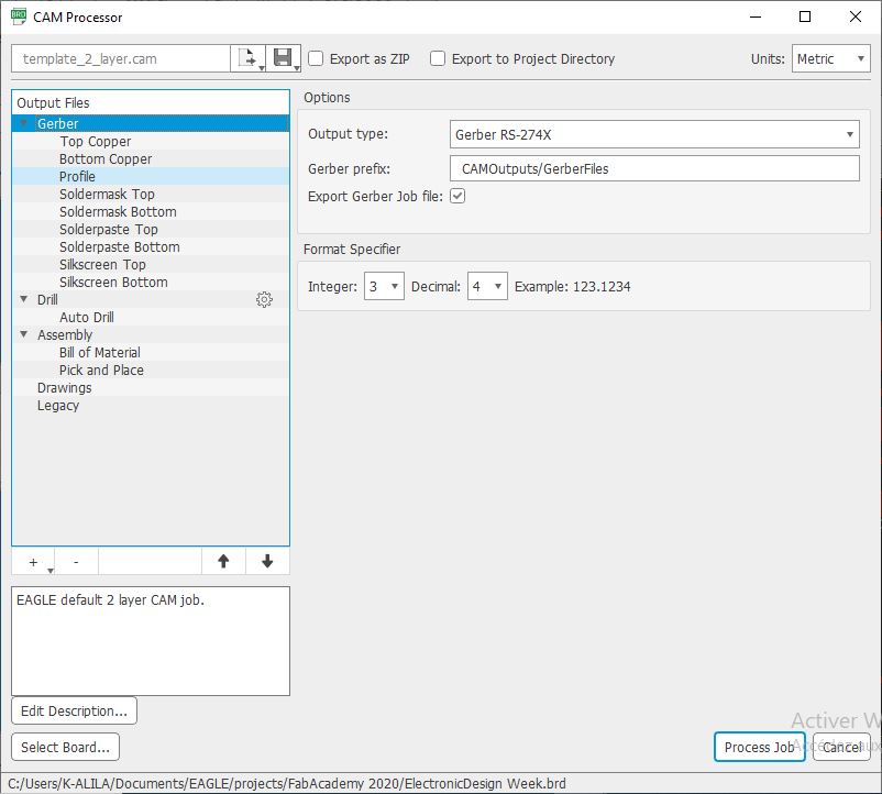
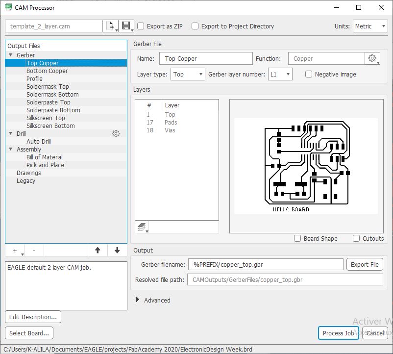
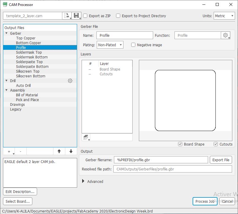
b. With this tool you can choose the layers and the job for your board and the export it gerber For example we usually need the Top Copper layer, the Bottom Copper and the Profile. It depends on your manufacturing process and your board complexity
If you have trough all components you can export the drill file XLN file.
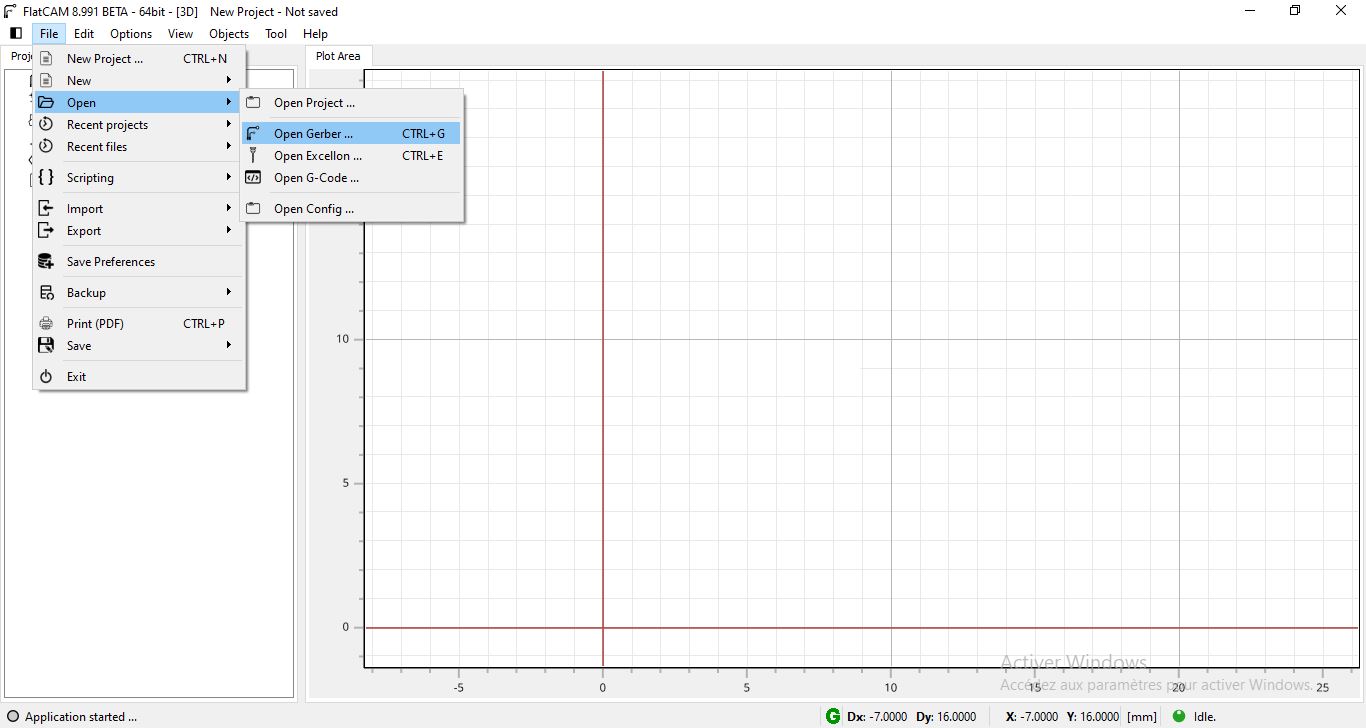
- Step2: FlatCAM lets you take your designs to a CNC router. You can open Gerber, Excellon or G-code, edit it or create from scatch, and output G-Code. Isolation routing is one of many tasks that FlatCAM is perfect for. It’s is open source, written in Python and runs smoothly on most platforms.You can download FlatCAM from this link
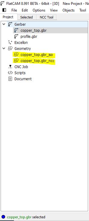
a. Open the gerber file and excellon files into flatcam.
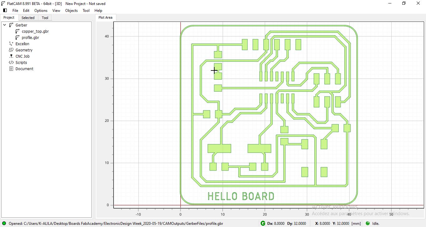
NOTE: To move the trace or the profile, you should select all then move the groupe. Also You should import all the gerber files and the drill file together at the same time before moving because you may lose the correct position of each layer. lat cam postion the layers correctly when you import them all after that you can ove the groupe. If you import the top copper for example and move it then import the drill file you miss the correct position of the drills on the board.
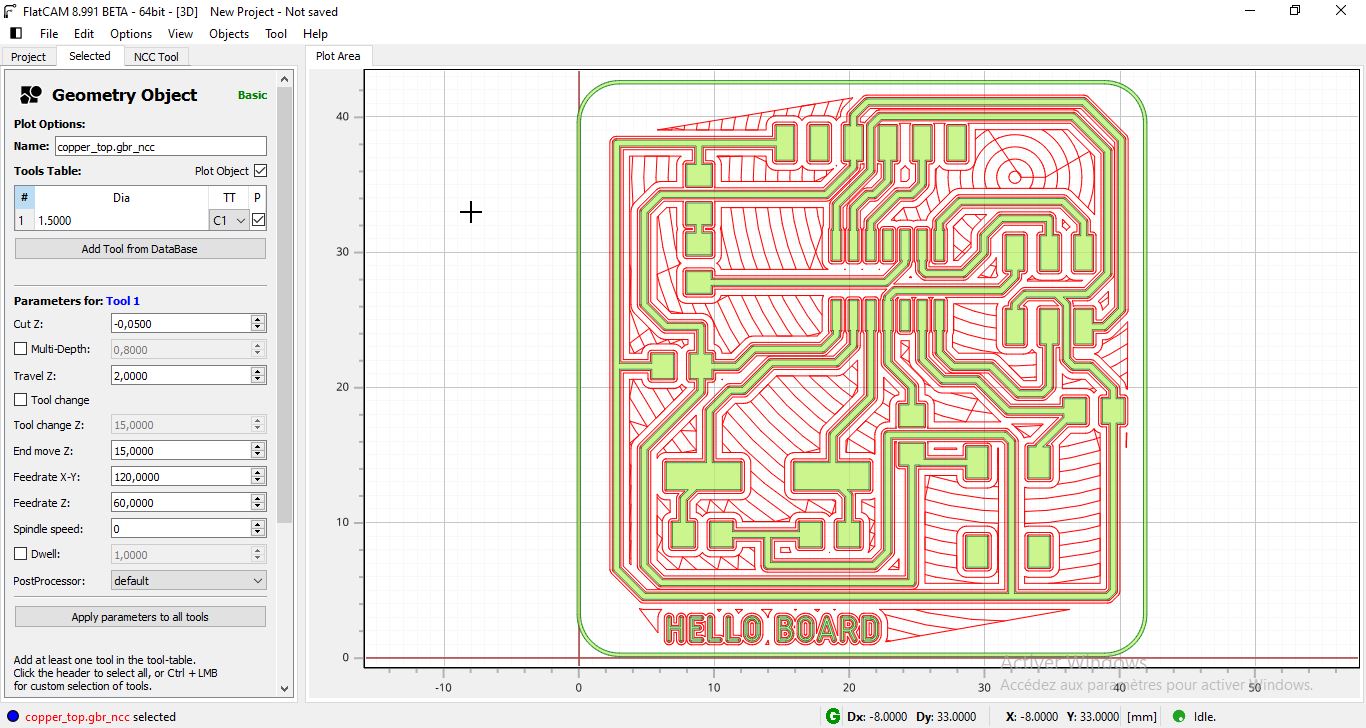
b. Double click on the top copper gerber file of the project manager. here where you will choose te tool diameter and the number of passes for the tracce. You can also use the NCC Tool (Non-Copper Clearing) process to mill the surface where we dont need copper and chose another tool diameter and the milling depth to make the process faster. After all that press Generate Isolation Geometry
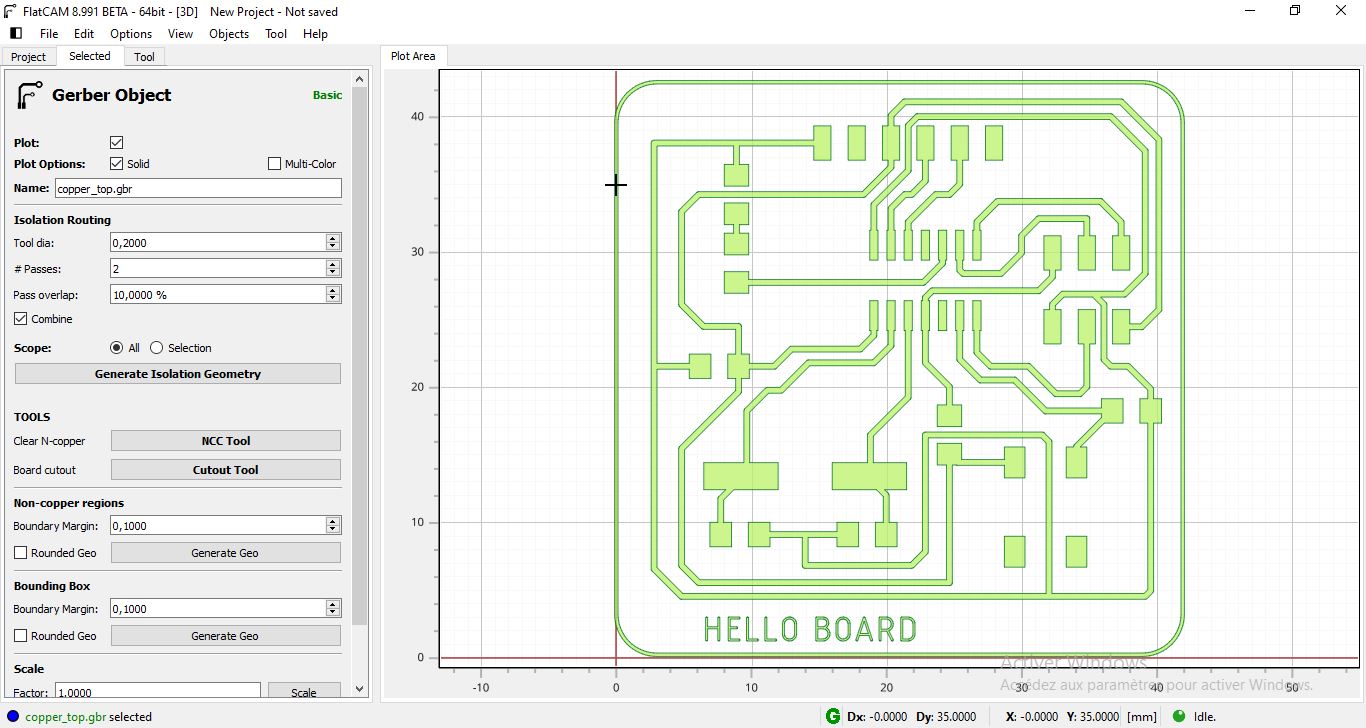
c. At this point you generated a geometry based on your design that defines also the tool path.
Previous Settings:
-
Tool diameter for trace: 0.2mm (it depends from the tool you have at the lab)
-
Tool shape for trace: V-shape (Generally used for pcb milling and for easy bord. For complex ones you need circular shape)
-
Tool diameter for NCC & Cutout: 1.5mm (it depends from the tool you have at the lab)
-
Tool shape forNCC & Cutout: Circular shape, Flat EndMill
d. The next step is to generate the toool path to have the g-code at the end. Double Click on the Geometry generated on the previous step. and enter the machining settings like the plunge speed, the cut depth , the default speed …
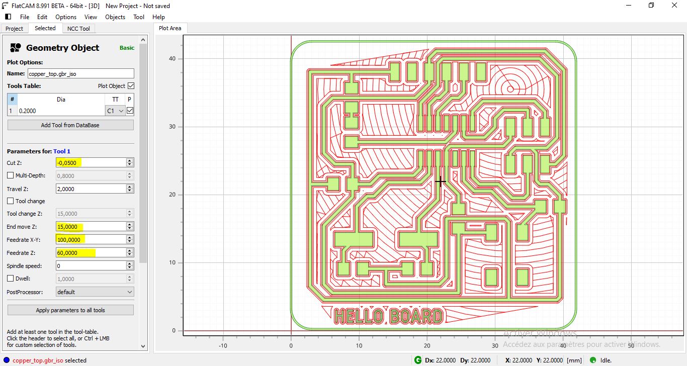
after many tests the best parameters for good quality board :
-
Cut depth: -0.05 mm
-
Tool realese distance: 5mm
-
XY Speed : 100 mm/min
-
Z speed or plunge Speed: 60mm/min
-
Spindle speed: 15000 Rpm (if you have PWM spindle)
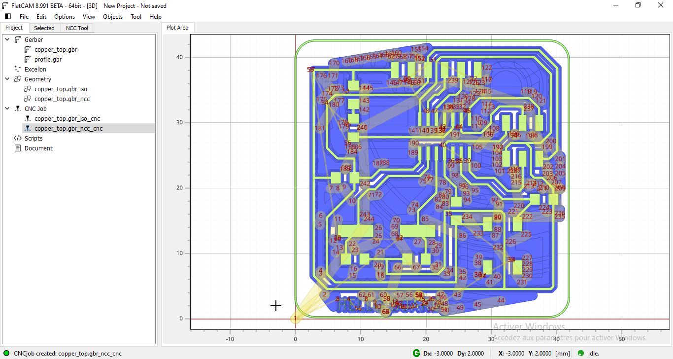
e. generate the tool path and finally you will have the g-code by double click on cnc job coammand
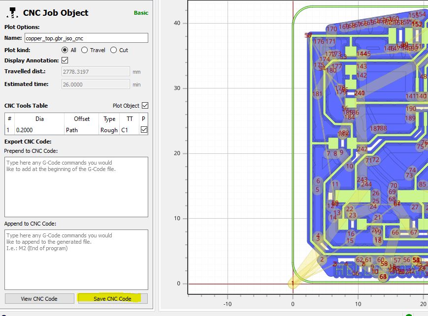
For this assingmnet, I wanted to test our old cnc machine Charly2u CNC machine. We used this machine only to mill wood, aluminium and POM. this will be my first test for milling PCB.

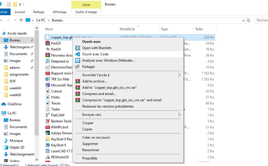
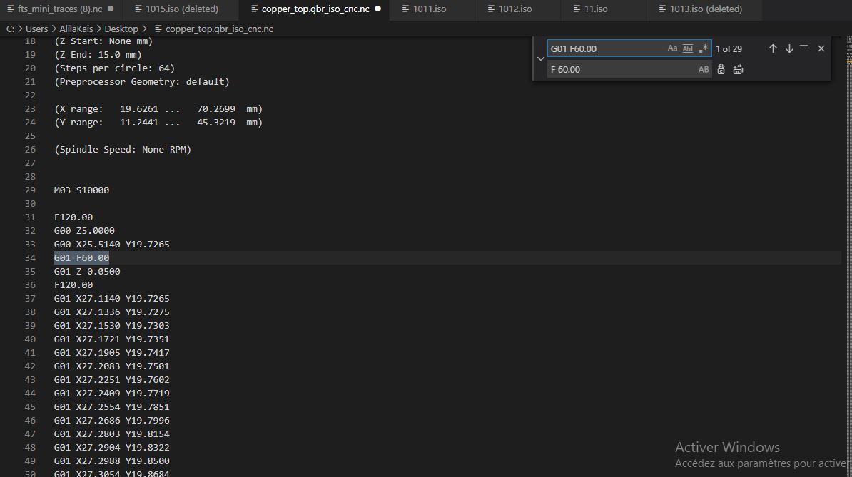
The machine command software was too old and do not accept many Gcode commands. So When we export from Flatcam an NC file we do some modifications.
-
Open the code generated with notepad or brackets …
-
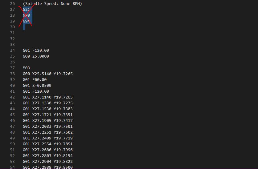
Delete the first three lines of the code G21 G90 G91 the machine do not understand these commands
-
Add the spindle speed to the code M03 S10000 or S10000 M03
 -
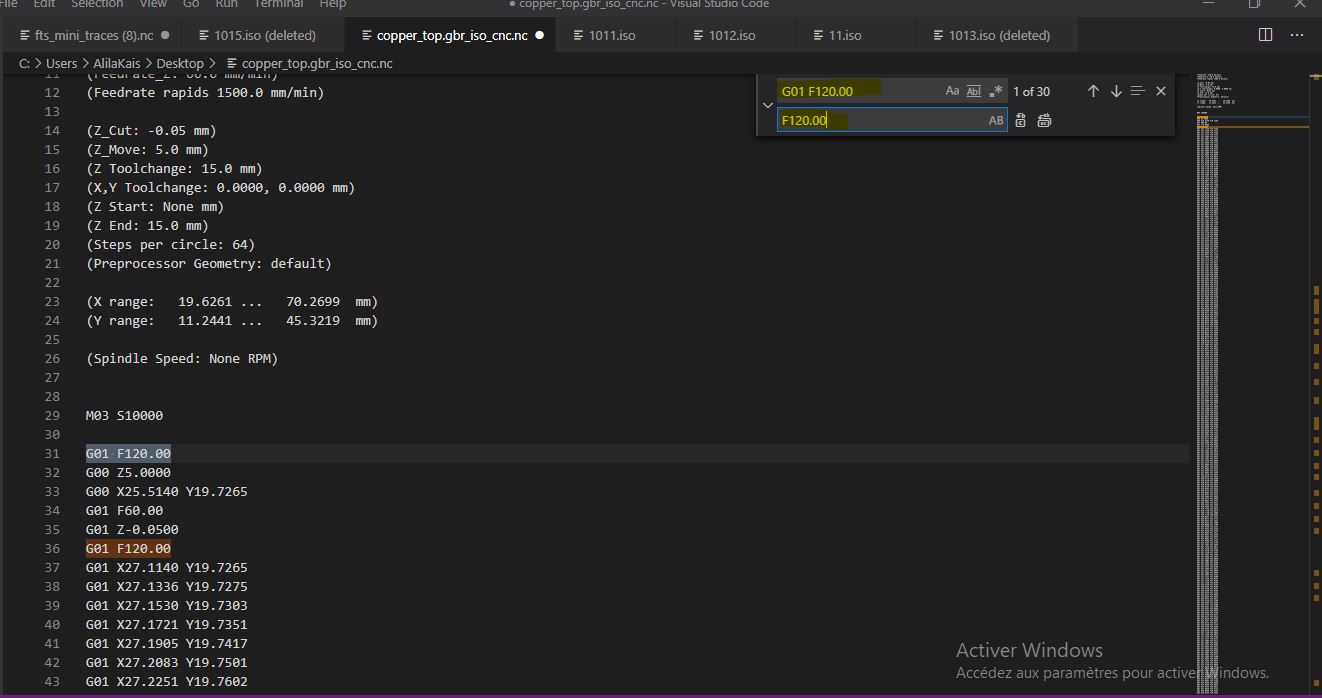
Replace all G01 F120.00 & G01 F60.00 with F120.00 & F60.00 (The machine software accept only the F: Feedrate command in a single line with no G01 or G00 before it )
-
Upload the g code to the machine and start milling
-
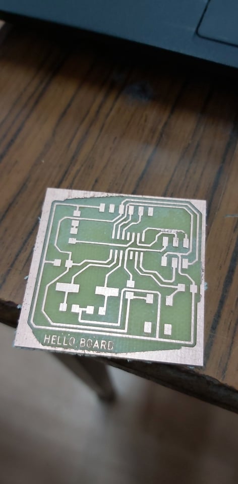
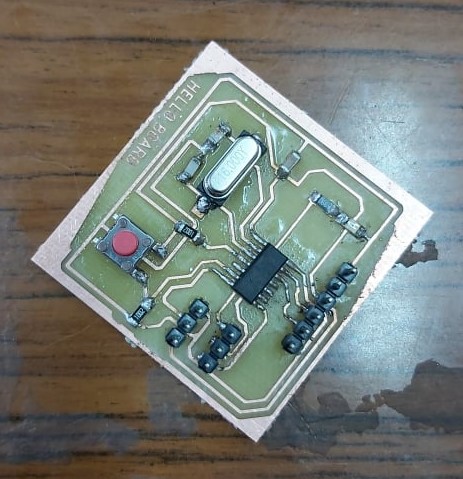
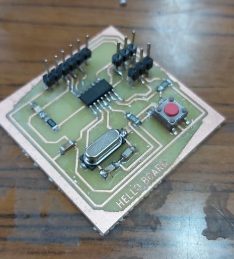
Result:
Assembling and programming
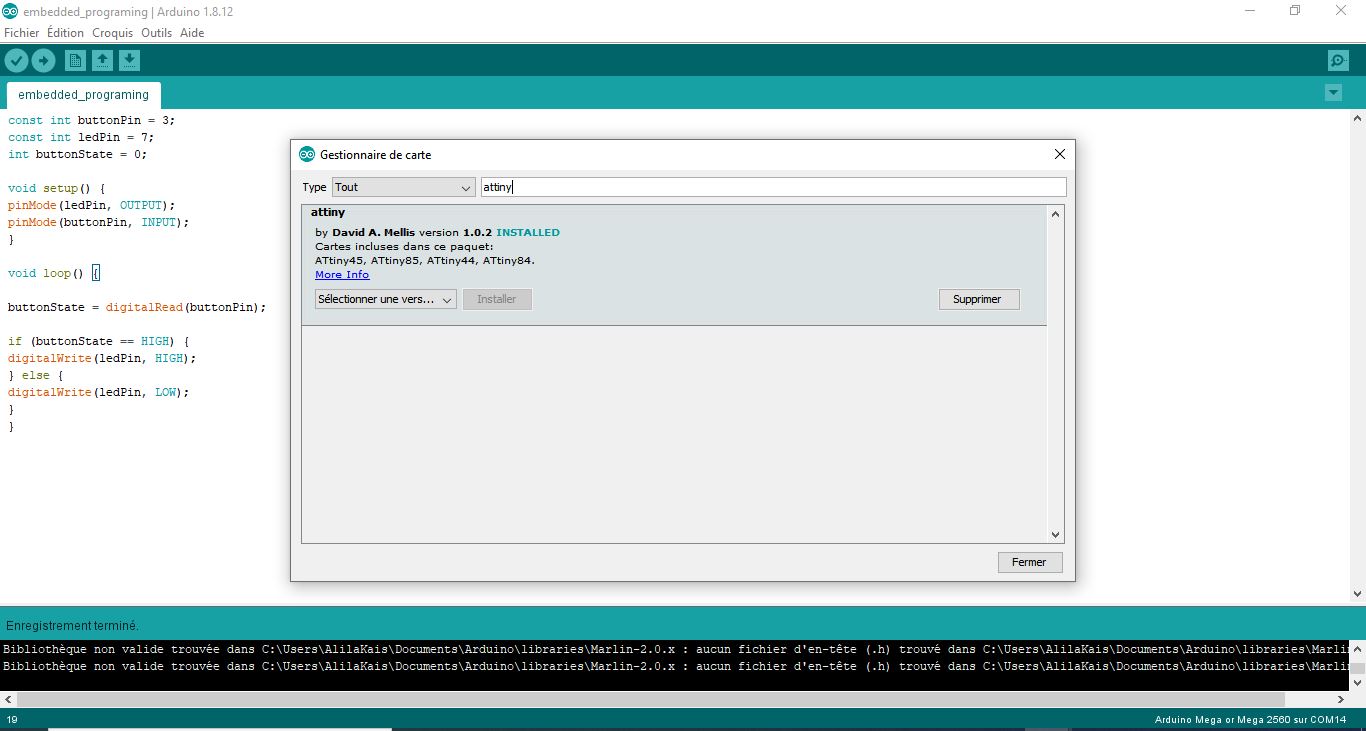
Before start programming The arduino IDE doesn’t recognize the attiny44 in your hello board by default so to fix that I uploaded the one from arduino library attiny by Davis A. Mellis version 1.0.2 from board managment features and intall it. like shown in the image below:
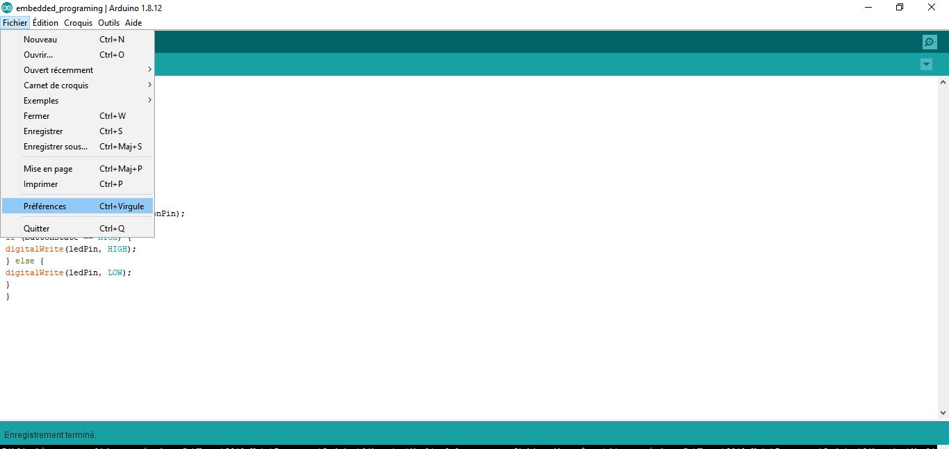
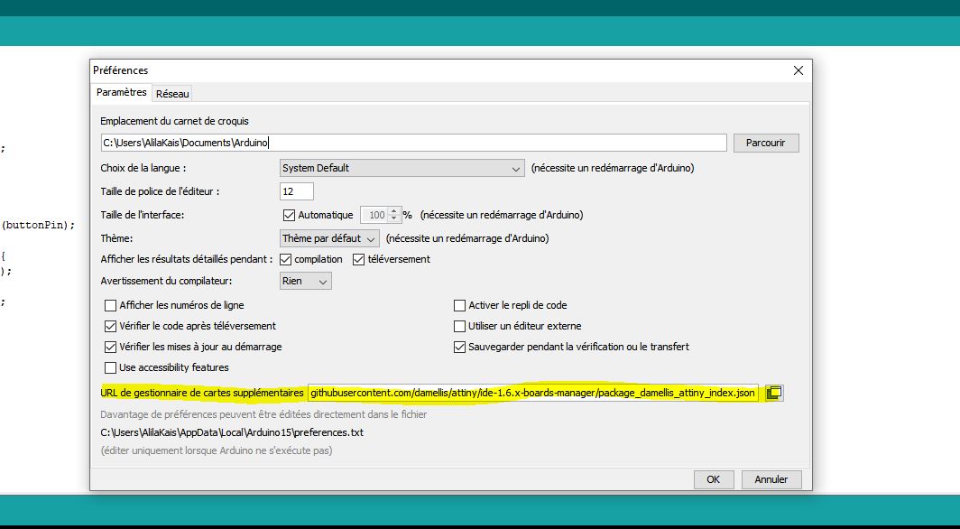
I also added the URL link for additional MCU in file>Preferences>additional board management url
URL Link: https://raw.githubusercontent.com/damellis/attiny/ide-1.6.x-boards-manager/package_damellis_attiny_index.json
After finishing the assembly phase move now to the programming phase.
- Connect the hello board to the arduino like shown in Electronic production week. pay attention to the right addressing of the MISO
on the Arduino IDE set parameters as follow
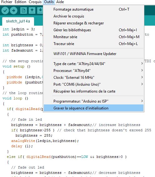
-
Burn Bootloader
-
open an example from arduino sketches.
-
now upload the program trough by your programmer
I programmed my board as follow:
int ledpin = 3;         // the PWM pin the LED is attached to
int pushbutton = 7;     // the Analog pin the Button is attached to

int brightness = 0;     // how bright the LED is
int fadeamount = 1;     // how many points to fade the LED by

// the setup routine runs once when you supply the board trough FTDI cable
void setup ()
{
  pinMode (ledpin,OUTPUT);    // declare pin 7 to be an output
  pinMode (pushbutton,INPUT); // declare pin 3 to be an input
}
// the loop routine runs over and over again forever
void loop ()
{
  if( digitalRead(pushbutton)==HIGH && brightness<255 )
  {
    // fade in led
    brightness = brightness + fadeamount;// increase brightness
    if( brightness>255 ) // check that brightness doesn't exceed 255
      brightness = 255;
    analogWrite(ledpin,brightness);
    delay (1);
  }
  else if( digitalRead(pushbutton)==LOW && brightness>0 )
  {
    // fade out led
    brightness = brightness - fadeamount;// decrease brightness
    if( brightness<0 )// check that brightness doesn't go below 0
      brightness = 0;
    analogWrite(ledpin,brightness);
    delay (1);
  }

}
Gorup Assignment
Here is the link for the group assignment page
Operation of a Microcontroller circuit board
CONTINUITY TEST
One of the commom and useful thing you want to do when building a circuit is to check the CONTINUITY of your components. The continuity test serves to check the presence of a current flow between points.
To test it set the multimeter to “continuity”, looks like an icon as follows:
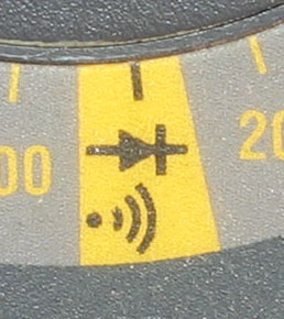
Test the probes by touching them together, they should emmit a bip! Using the probes touch different separate pins. If you hear a tone it means they are connected.
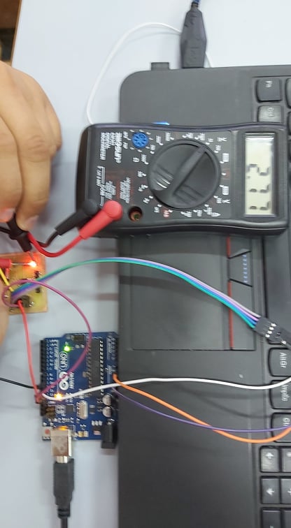
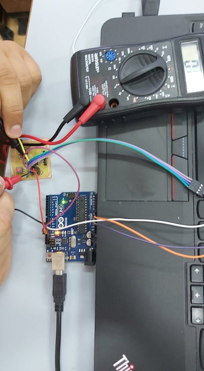
VOLTAGE TEST
Find the correct Voltage you are using to supply your LED or your board using the probes touch respectively the Vin and GND, but remember to set the right scale and set the multimeter to read DC current. In my case I’ve set the scale on 20V to read the 5V or 3.3V I need: