9. Embedded programming
Group assignment
Here is the link for the group assignment page.
Individual assignment
Data Sheet
A datasheet is a document, printed or electronic that provides details about a product, like a computer, computer component, or software program. The datasheet includes information that can help in making a buying decision about a product by providing technical specifications about the product.With a computer system, a datasheet could list what a computer includes such as how many USB ports, CD or DVD drive, hard drive, processor, memory (RAM), and video card. It may also list the specific features of the motherboard in the computer. With software, a datasheet could list a program’s features and the system requirements, like operating system, processor, memory, video card, and any other system requirements.
Microcontroller Data Sheet
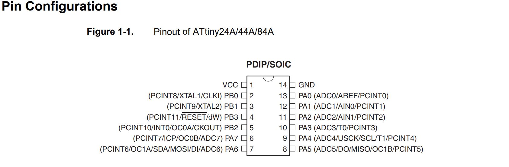
PINx - PORTx - DDRx
The ports are bi-directional I/O ports with optional internal pull-ups. Each port pin consists of three register bits: DDxn, PORTxn, and PINxn.
According to 10.3 Register Description / ATtiny24A/44A/84A / 8183F–AVR–06/12, I choose ports that I used for my project:
-
PA3 as OUTPUT;
-
PA7 as INPUT for button switch;
Note:
DDRB or DDRA = DATA DIRECTION REGISTER: it means the direction of this line of data it will be OUTPUT or INPUT
PORTB or PORTA = this is the line of the output data
PINB or PINA = this is the line of the input data
and Letters A / B that associate with the DDR or Port or Pin are just as name.
#include <avr/io.h>
#include <util/delay.h>


int main (void)
{
    // with OR-operation set bit number 3 in DDR register, make it output (LED)
    DDRB |= (1 << PB3);
     // clear bit number 7 in DDRB register,  make it input (BUTTON)
    DDRB &= ~(1 << PB7);

    while (1)
    {  // with AND-operation check if bit 1 is set
        if (PINB & (1 << PINB7)){
          PORTB &= ~(1 << PB3);


    } else  {

         PORTB |= (1 << PA3);

    }
}
}
in this video I’ve test the same code . the process is the same in the Electronic design assignment
Programing My Hello Board
As done in the previous assignment, I programed the board using an arduino and SPI comunication.
Like the Electronic production week, I uploaded the arduinoISP code in my arduino uno then I connected the two board together MISO with pin 12, MOSI with pin 11 , SCK with pin 13, RST with pin 10 and the 5v and GND with the appropriet pin.
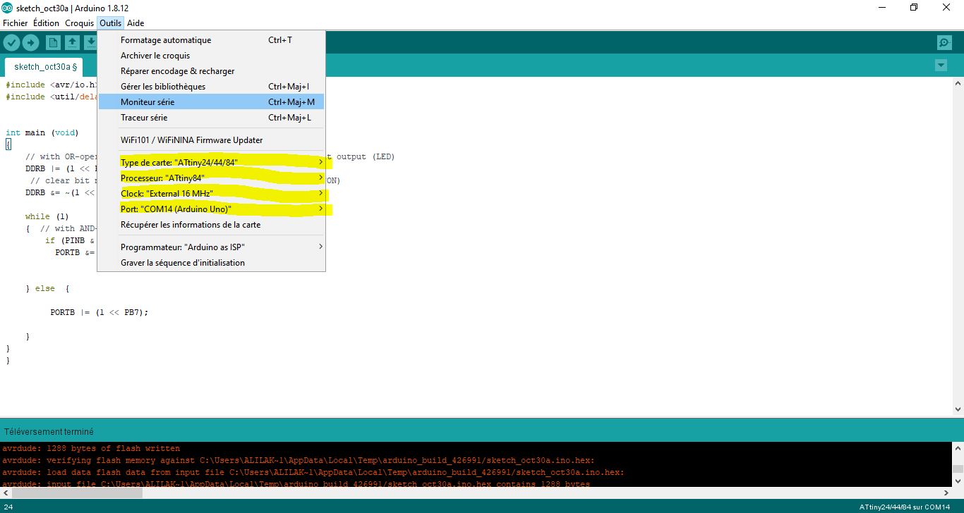
After that I burned the bootloader and then upload the code with chosing the correct settings.
My “Arduino” Code
I’ve made the same example above, but I wrote it in Arduino IDE.
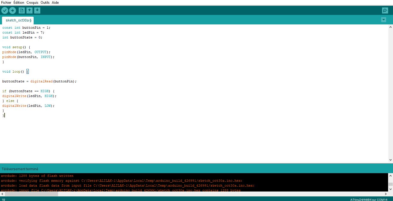
This is my code:
const int buttonPin = 3;
const int ledPin = 7;
int buttonState = 0;

void setup() {
pinMode(ledPin, OUTPUT);
pinMode(buttonPin, INPUT);
}

void loop() {

buttonState = digitalRead(buttonPin);

if (buttonState == HIGH) {
digitalWrite(ledPin, HIGH);
} else {
digitalWrite(ledPin, LOW);
}
}
Note:
Using two different kind of code I can verify that, with same functions:
1- Compiled in C code is 148 bytes of flash written;
2- Compiled Arduino code is 892 bytes of flash written.