6. 3D Scanning and printing
Group Assignment
Here is the link for the groupe assignment page
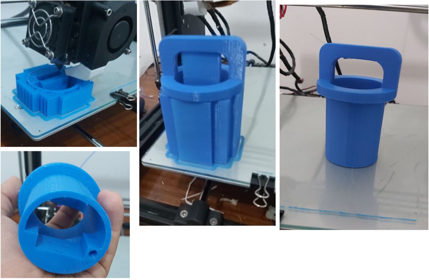
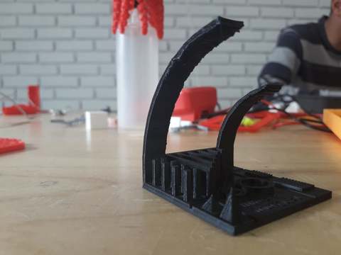
For the group assignment,we want to test the 3d prints to learn how to use this technology and also to test the machine performance. So first we use Raise 3D N1 printer and ultimaker 2.
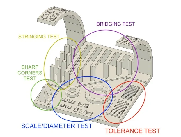
For the first test with Raise 3D N1, we used a design from thingiverse and printed it to understand the different prenting parameters. This is the Test file.
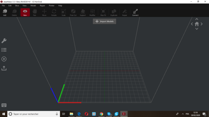
We also use the ideaMaker as a software to set the parameters, in the following pictures I will detail what we did:
1- Import file from your computer, click on the import button.
2- Choose your file.
3- Modify the layer parameters : set the height of the layers to 0.1mm and the first layer height to 0.15mm
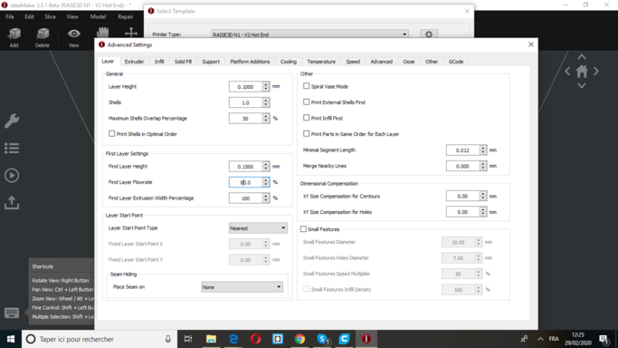
4- Since Nozzle diameter is 0.4 mm the extrusion width has to be changed to 0.4mm too. Modify Infill density to 10% and infill pattern type to Grid
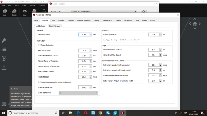
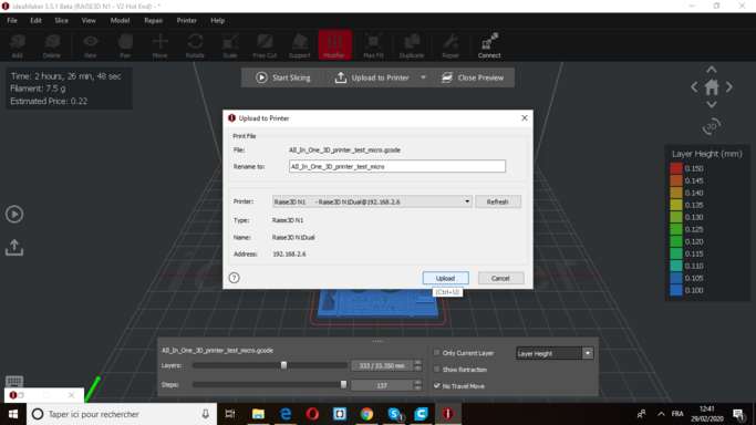
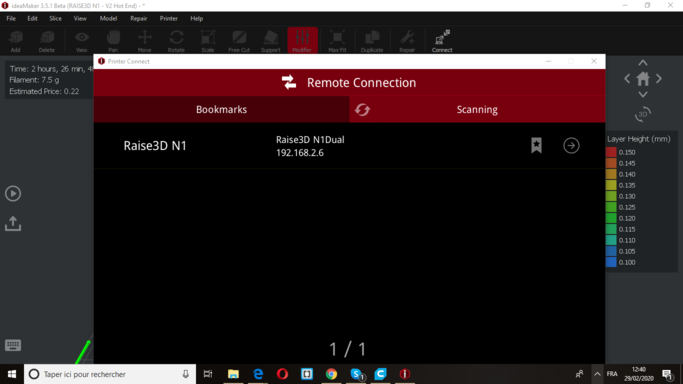
Several other optional parameters have been modified during this assignment group. After we were done, we connected my computer to the printer (it was really cool, just open your printer and control it from your desk).
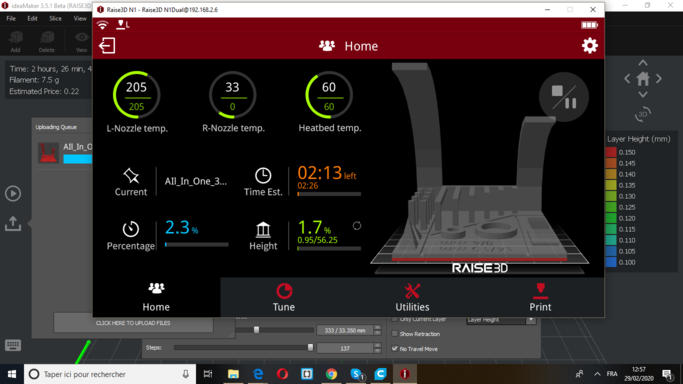
When the download is finished you can see your part and its information indicating the printing time, the current printing level, and the temperature of your printer …
This was our first test , you can see that there are defaults so it is necessary to choose the parameters well.
3D Scanning
Photogrametry
What is Photogrametry ?
Photogrammetry is the science of making measurements from photographs.
The input to photogrammetry is photographs, and the output is typically a map, a drawing, a measurement, or a 3D model of some real-world object or scene. Many of the maps we use today are created with photogrammetry and photographs taken from aircraft.
For this week assignment I am using this technique to scan objects, then I will Recap photo from autodesk to create the 3D model.
Step 1: Image acquisition
The shooting quality is the most important and challenging part of the process. It has dramatic impacts on the quality of the final mesh.
The shooting is always a compromise to accomodate to the project’s goals and constraints: scene size, material properties, quality of the textures, shooting time, amount of light, varying light or objects, camera device’s quality and settings.
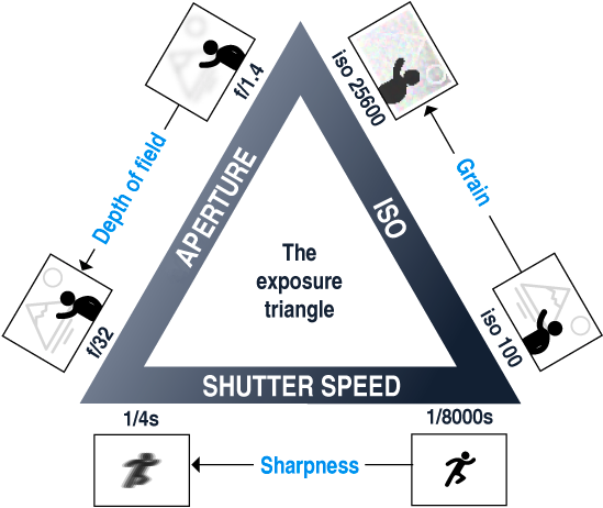
The main goal is to have sharp images without motion blur and without depth blur. So you should use tripods or fast shutter speed to avoid motion blur, reduce the aperture (high f-number) to have a large depth of field, and reduce the ISO to minimize the noise.
To provide all the required conditions for image acquisition i used my small shooting studio I use it usually for product shooting.
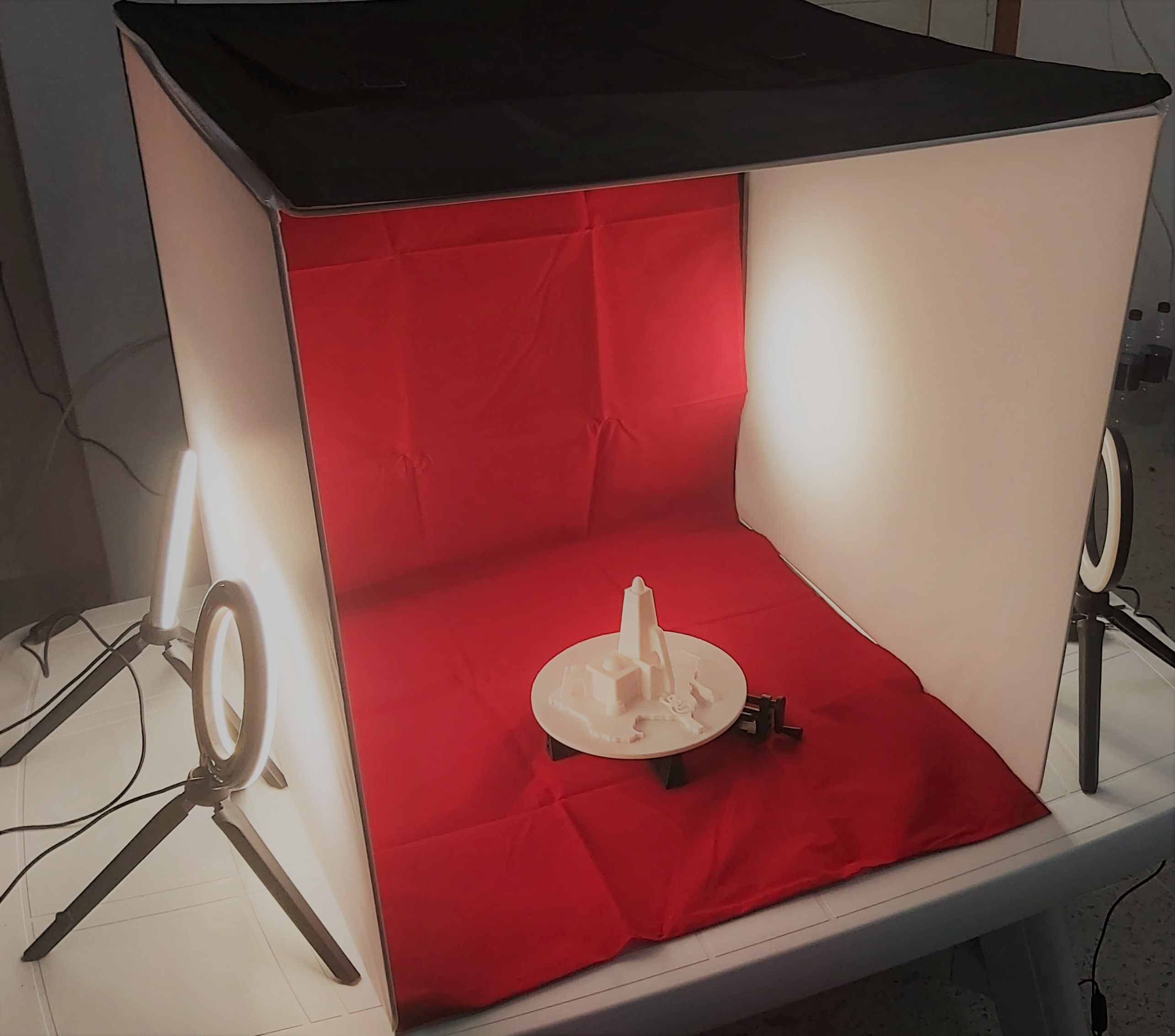
after taking 64 photo using my phone. The next step is using Autodesk ReCap Photo to create the 3d model.
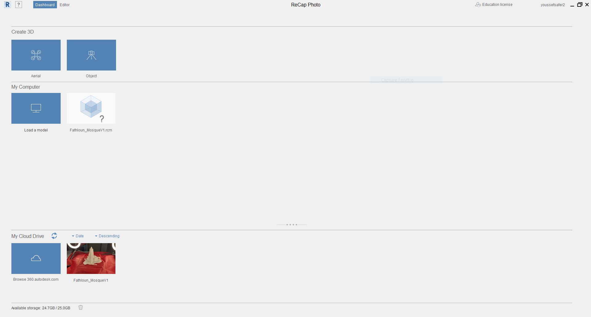
ReCap Photo

ReCap Photo processes photographs taken from drones to create 3D representations of current conditions of sites, objects, and more. To download Recap here the link.
- Step 1: Upload images, Create 3D –> Obejct –> Upload images.
After uplaoding the images and the calculations are done, we will have a mesh for the 3D model with the environment.
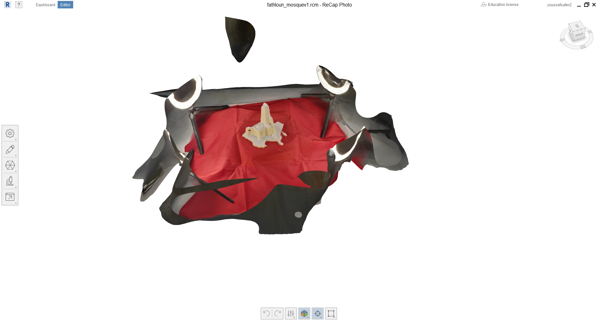
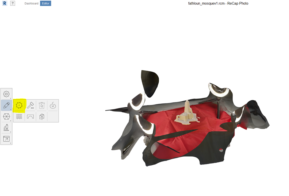
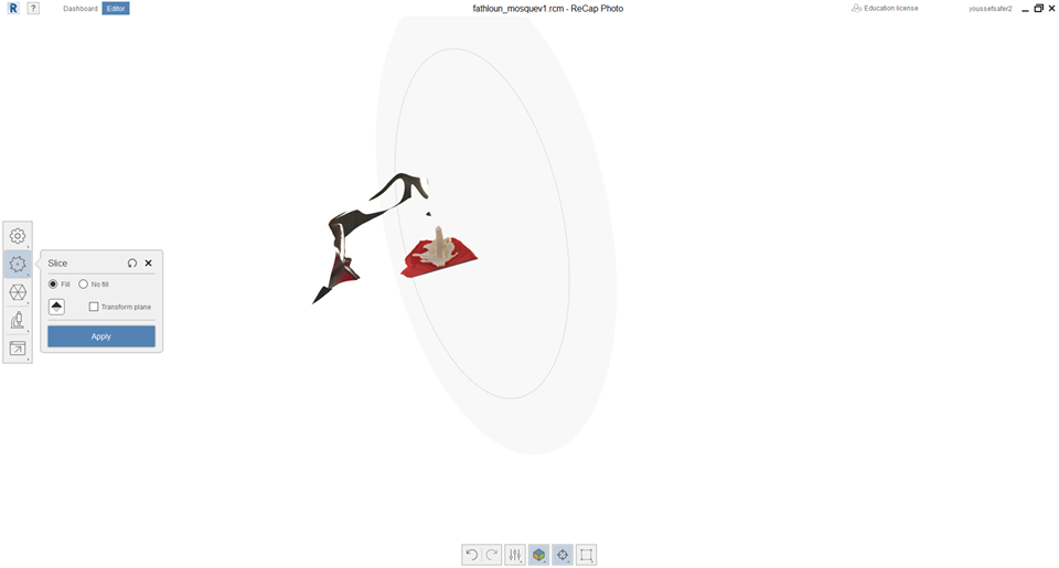
- Step 2: Delete the backgroud using the slice cutting tool
- Step 3: Set the model dimensions.
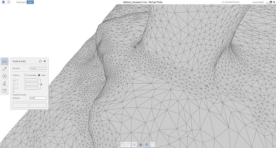
To issue of photogrametry is that the model is not metrologic so using this method can not have a very precise result. To solve the issue, I used the scale & units tool to do that. I measured one dimension in the real model and enter the value in the mesh like shown in the previous image.
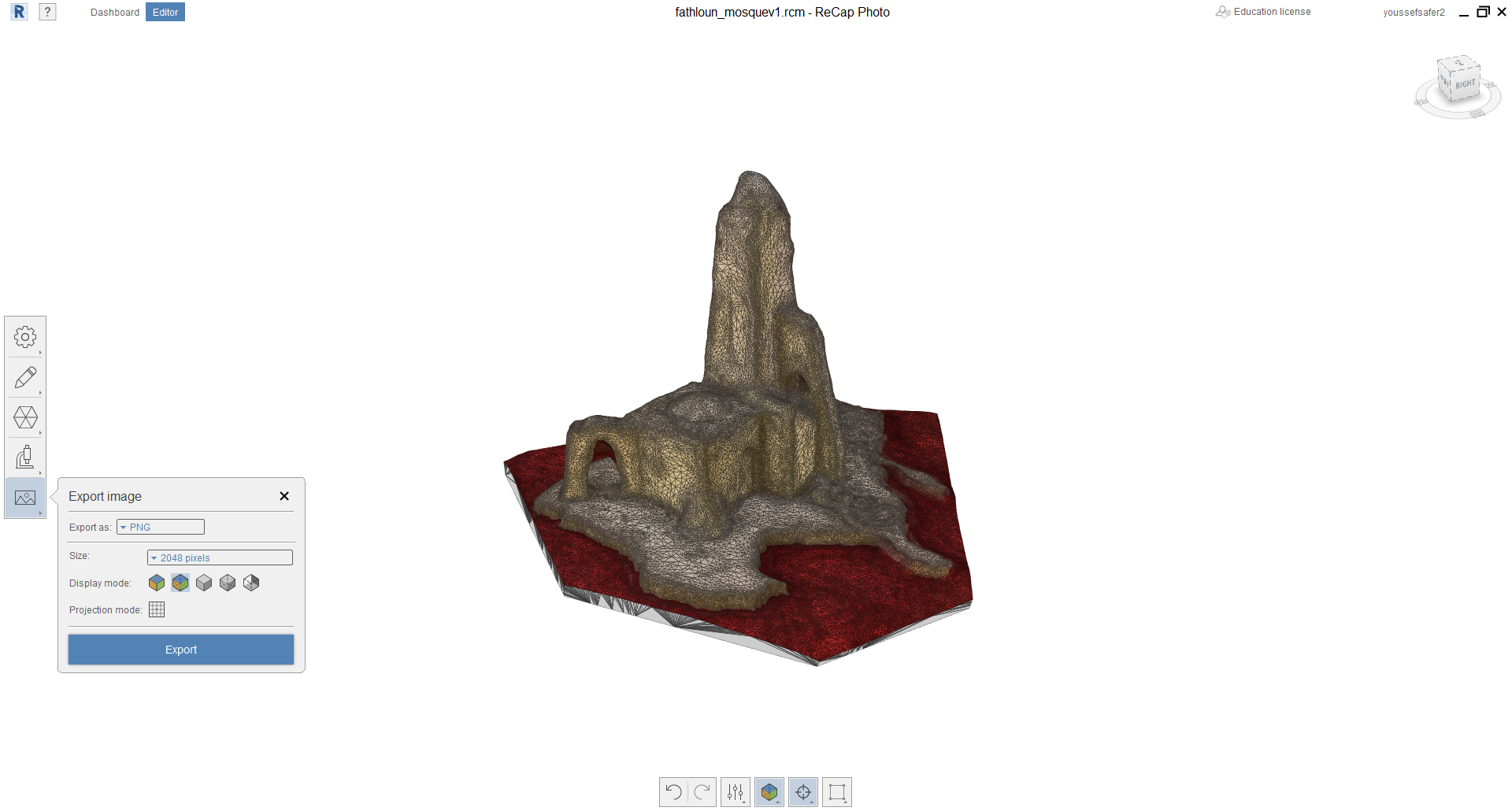
- Step 4: export the 3D model to the format you need.
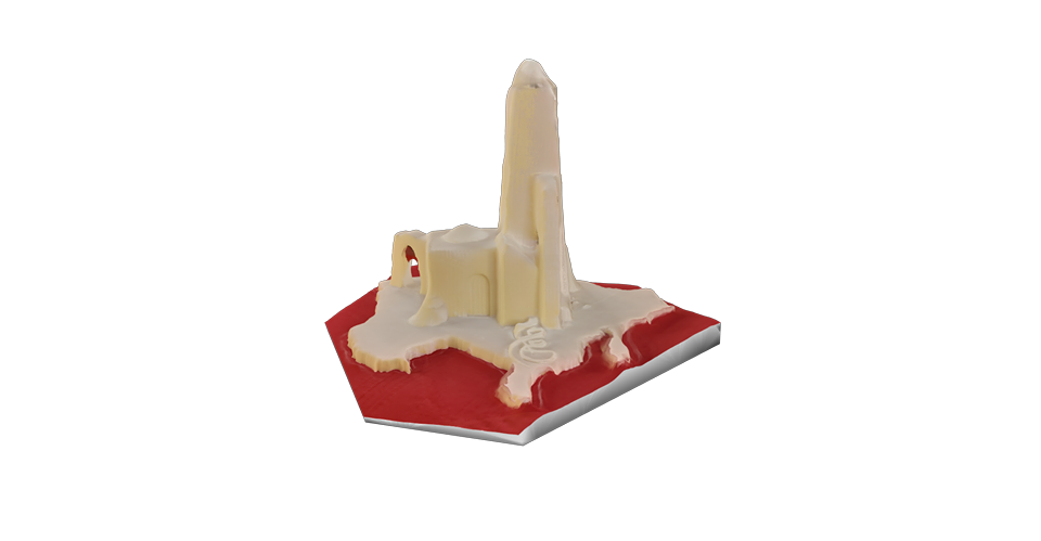
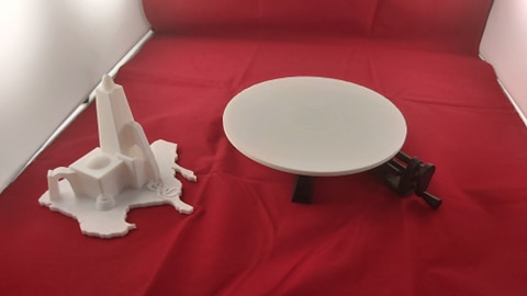
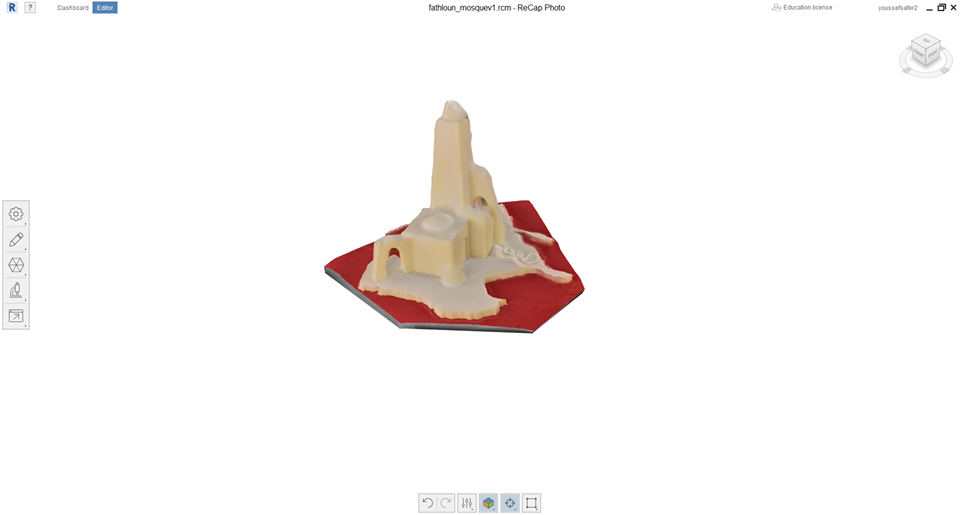
3D model Result :
Download files: FathlounMosque STL, Recap file
3D Printing
3D Design

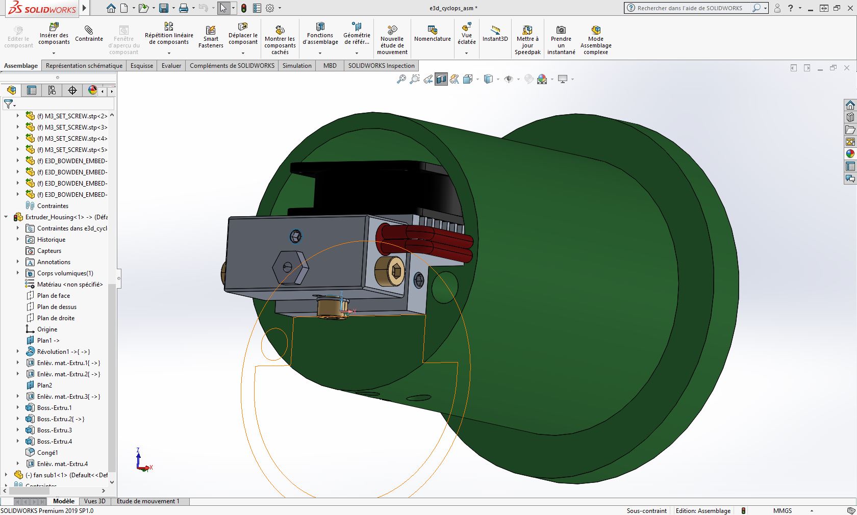
The machine uses 3 diffrent tools for the diffrent digital manufacturing operations (Laser engraving Tool, 3d printing Tool, CNC milling tool). For both laser & extruder, I modled the housing, which is a very important piece to fi the extruder or the laser on the machine tool holder.
For this week, I chose to design the Extruder housing. I will use 2in1 dual extuder (E3D cyclops).
- Step1 : I downloaded the dual extruder from grabcad here is the link and then I open it in solidworks.
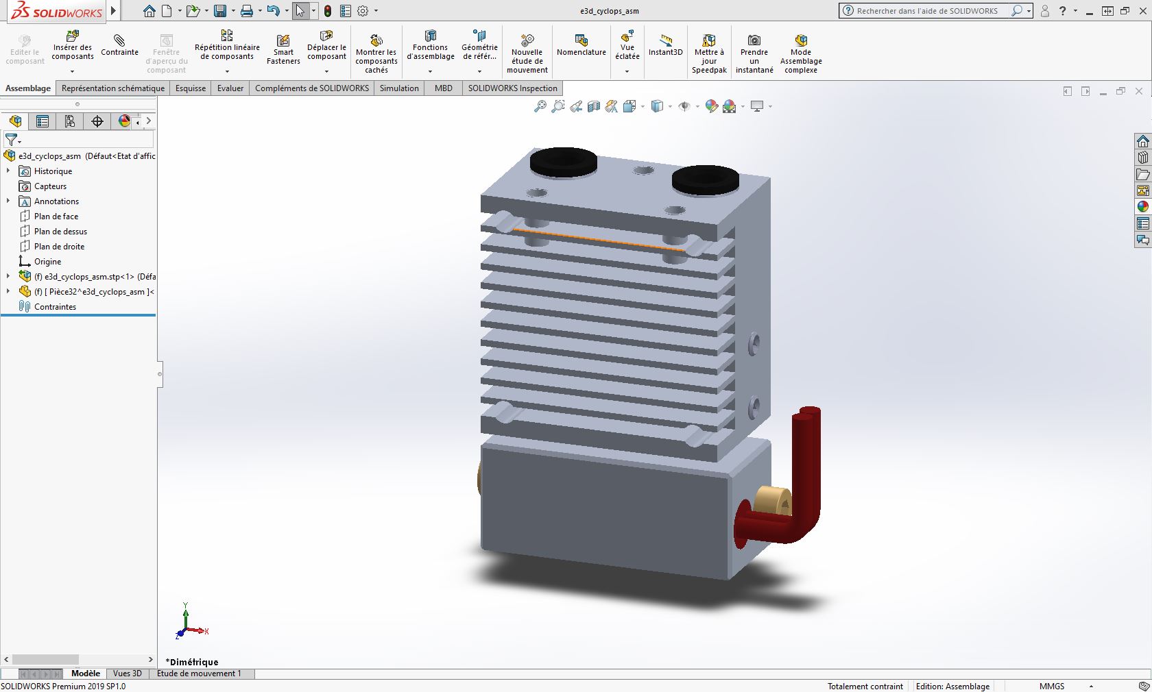
- Step 2 : Start a new part named housing on the extruder assembly file
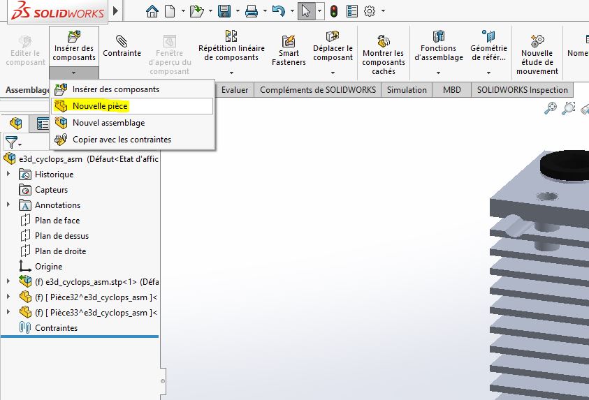
Select a plan to start the sketch on. (The extruder will be transparent)
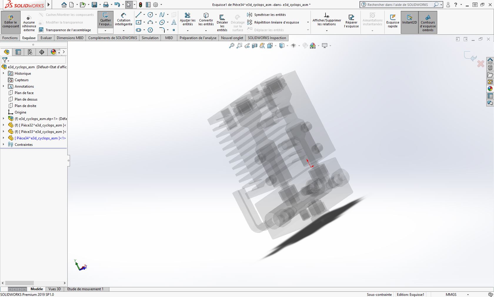
- Step 3 : Start creating your model (Extrude, Revolve …)
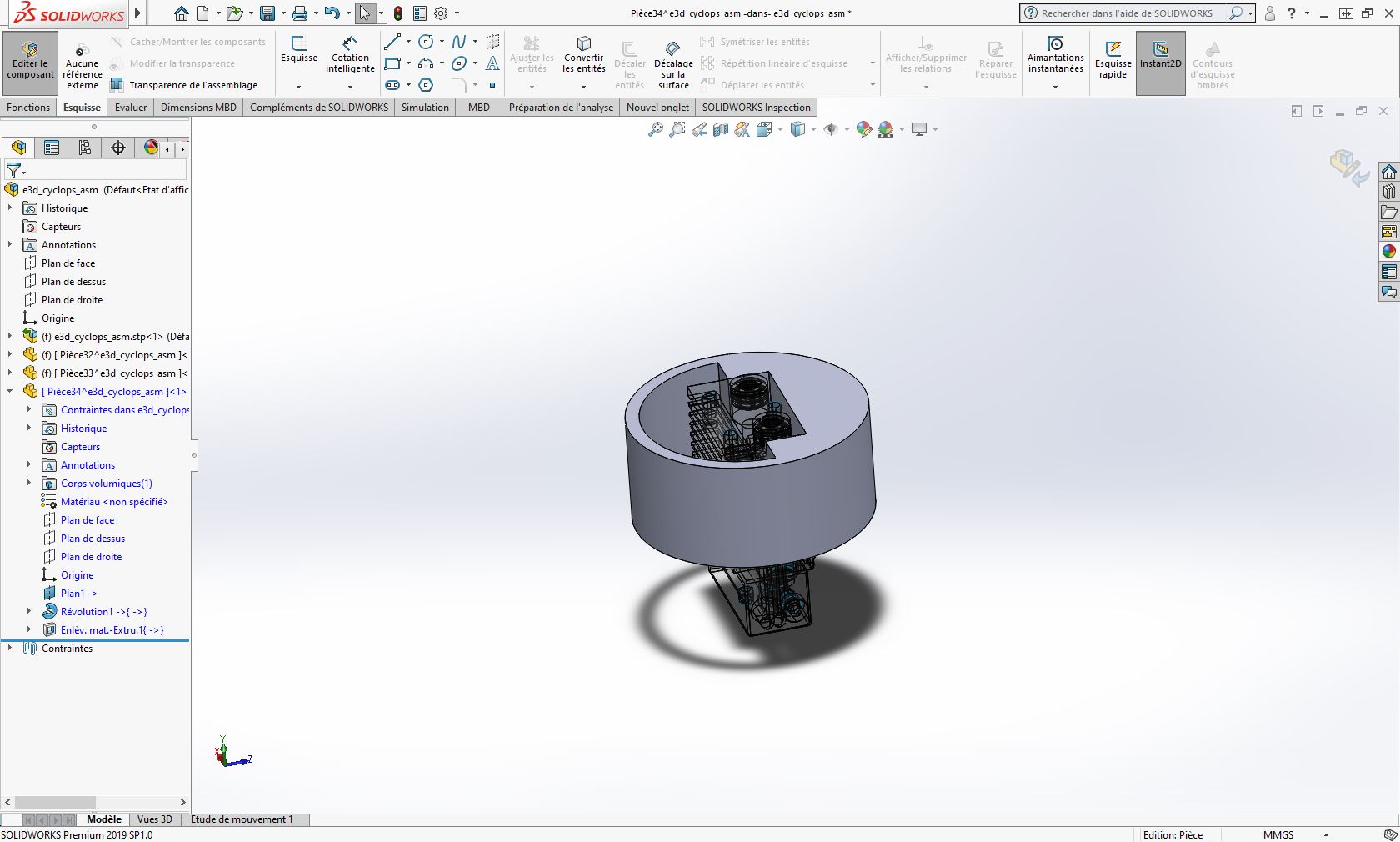
- Step 4 : I added the cables hole in the model to make the housing compact and fast to assemble
- Step 5 : Export the file to STL for 3d printing.
Download files:solidworks STEP file STL file
- Step 6 : Import the Stl file to fusion.
I use usually Simplify3D to generate the gcode for my 3D printer
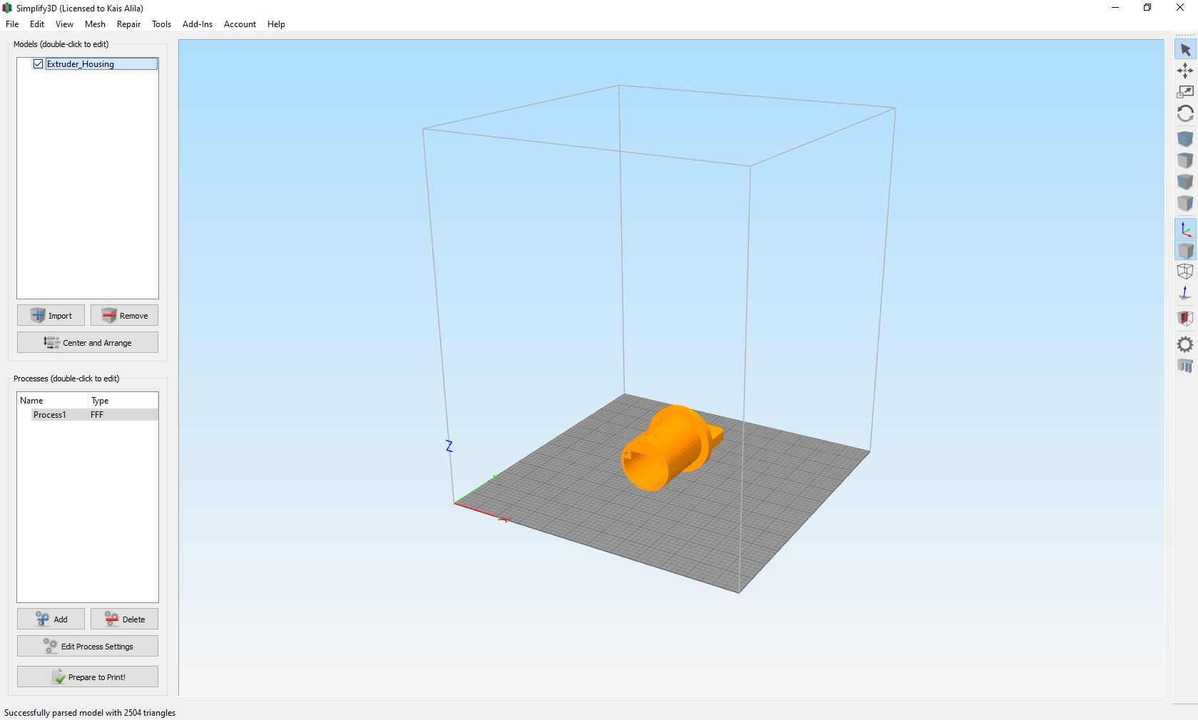
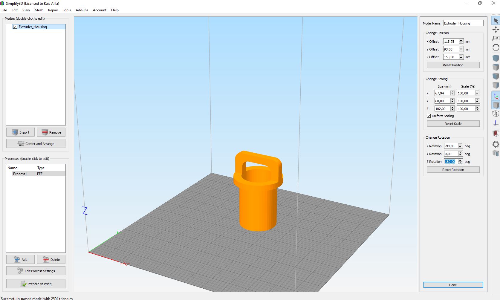
- Step 7 : Make the model in the correct orientation for 3d print.
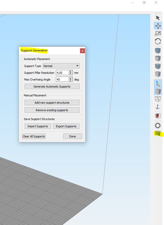
- Step 8 : In our case, it is necessary to add supports in this orientation.
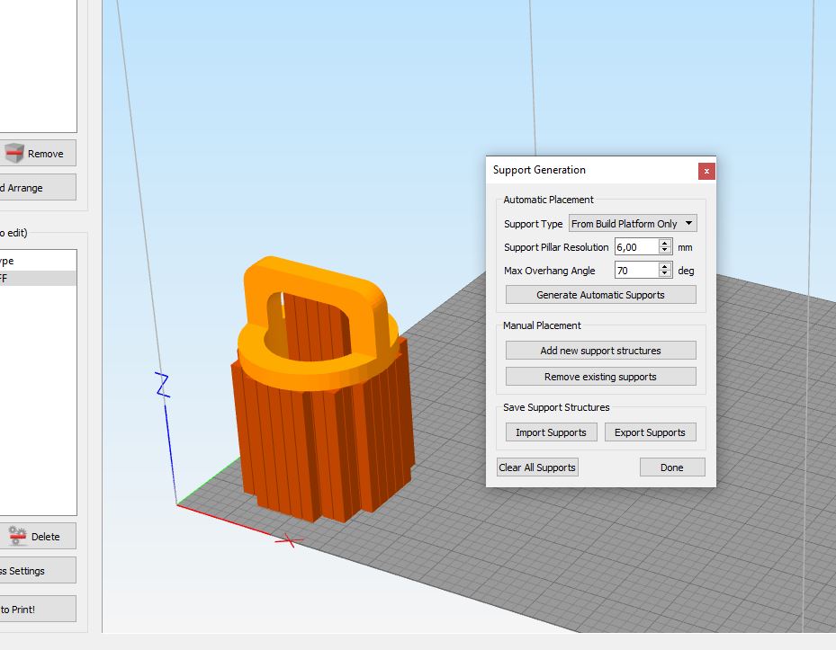
- Step 9 : add parameters & setting.
In our case, I will use my 3D printer Anet A8 + so you have to make sure to enter the good setings for your printer.
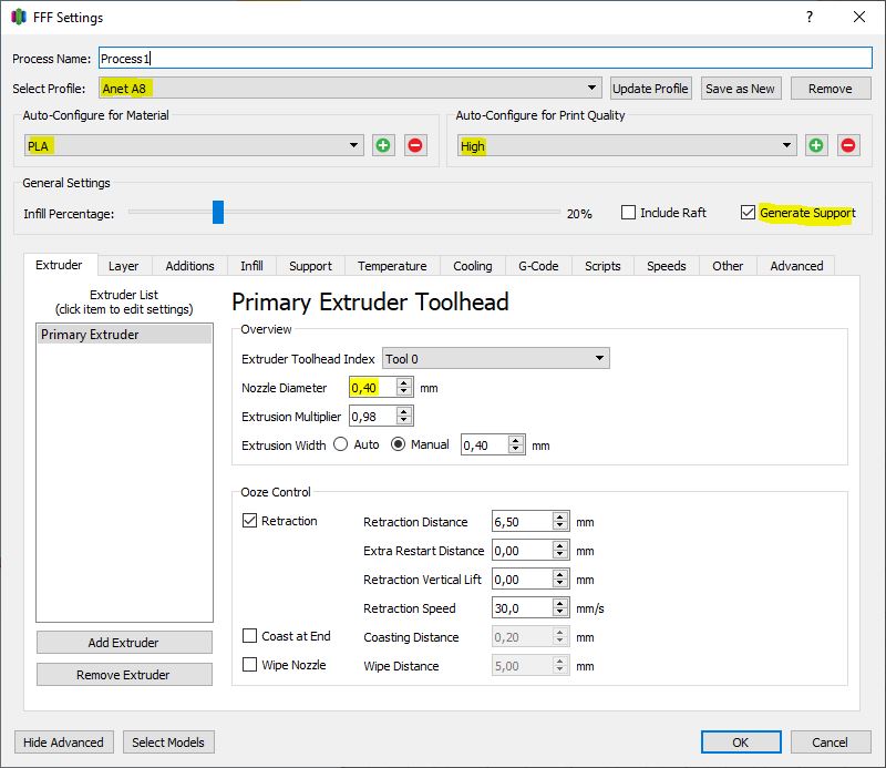
Press Prepare to print.
- Step 10 : Load the Gcode to your printer
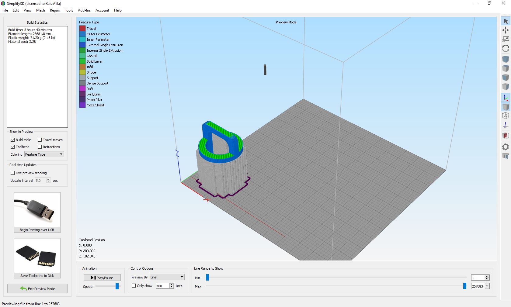
Note: Printing Parameters
  *Application version: 4.1.2
  *Estimated print time: 5h 40m
  *Material usage: 23m (71g)
  *Printer: Anet A8 +
  *Profile: Last settings
  *Support: 70° 6mm 15%
  *Gap XY: 0.28
  *Spacing: 3.50
  *Material: PLA
  *Nozzle diameter: 0.4 mm
  *Layer: 0.2 mm
  *Quality: High
  *Infill: 20%
Results