Group Assignment: 3D_Scanning_and_Printing
test the design rules for your 3D printer(s)
Fab Lab Kamp-Lintfort
This week’s group assignment of FabAcademy was about the basic design rules of 3D printing and scanning.
Additionally, as an individual assignment, I had to perform a simple 3D-scan, as well as a 3D-pring that wasn’t possibil using a milling machine or another subtractive method.
Group Assignment
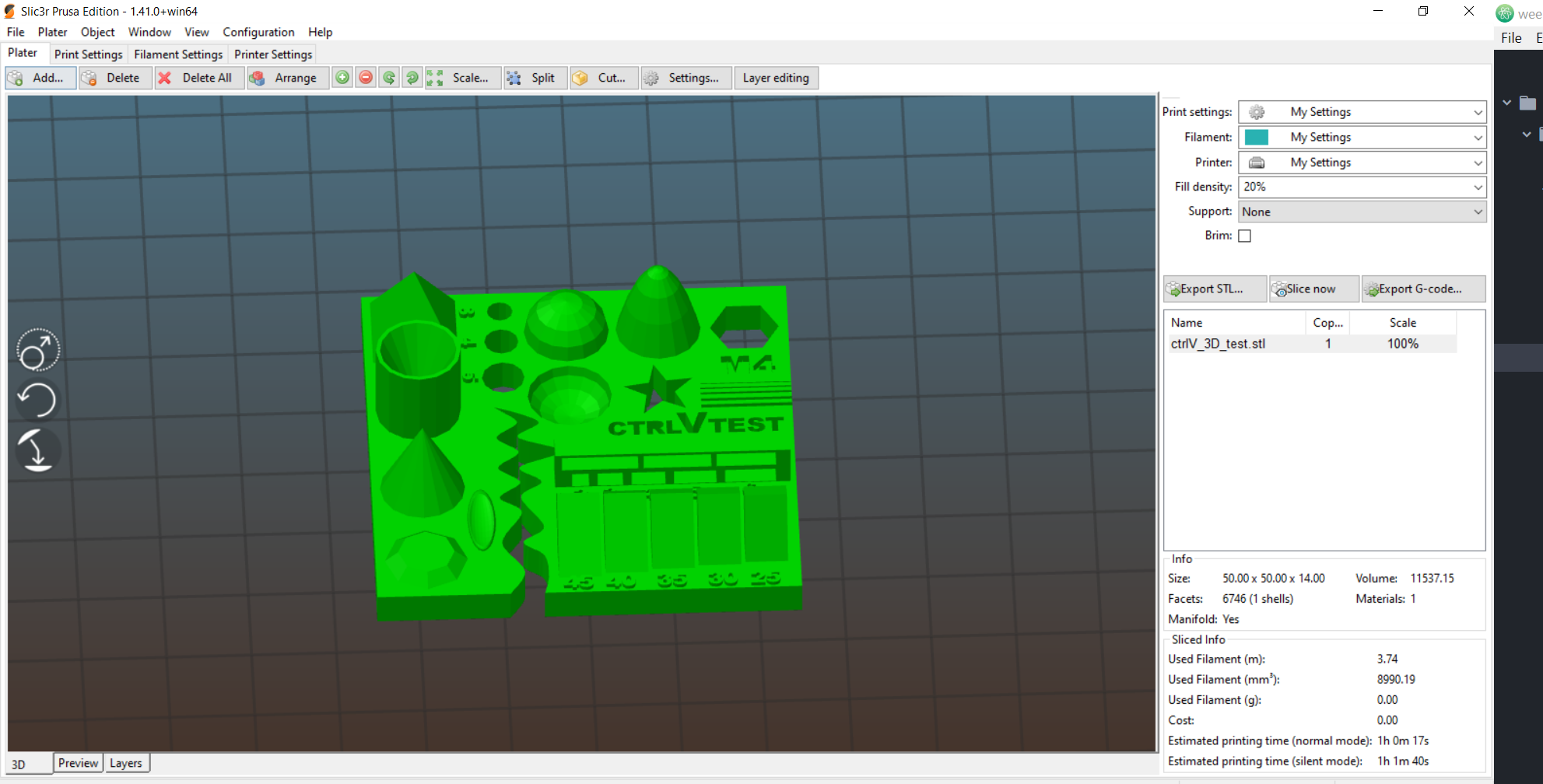
In the group assignment we made a model to check the design rules for our 3D printer:
No eavesdropping! I had to review the files of previous Fab Academians to get a foothold of what is needed. Out of which I found the one from Antti very helpful. In the site, Antti provided a link to this website. This contains an all-in-one 3D printable calibration test which can determine many different issues and problems all at once. The file can be downloaded from the LINK.
So what I will do is to print it on 3 of our 3D printers at the Lab. I will use Ultimaker 2+, Ultimaker 2 Extended+, and Prusa I3 MK3S printers to print the test object.
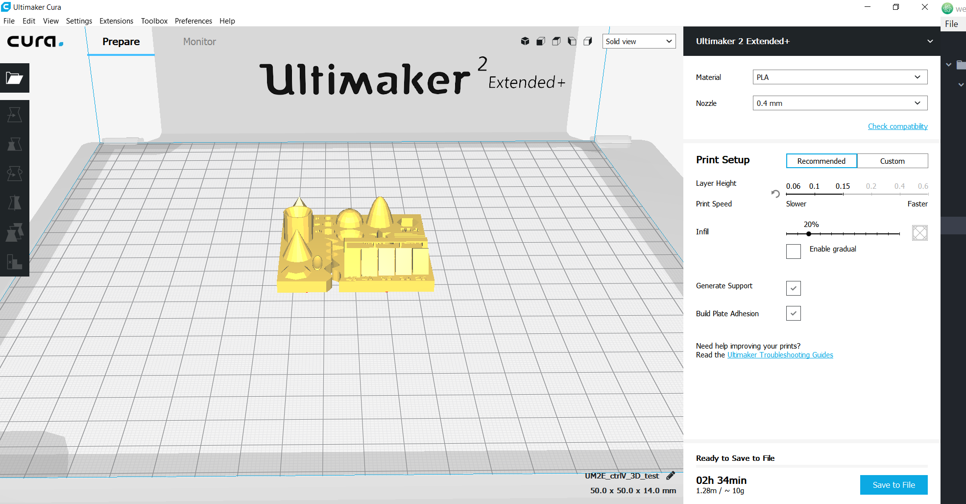
Ultimaker 2 Extended+
Ultimaker 2+
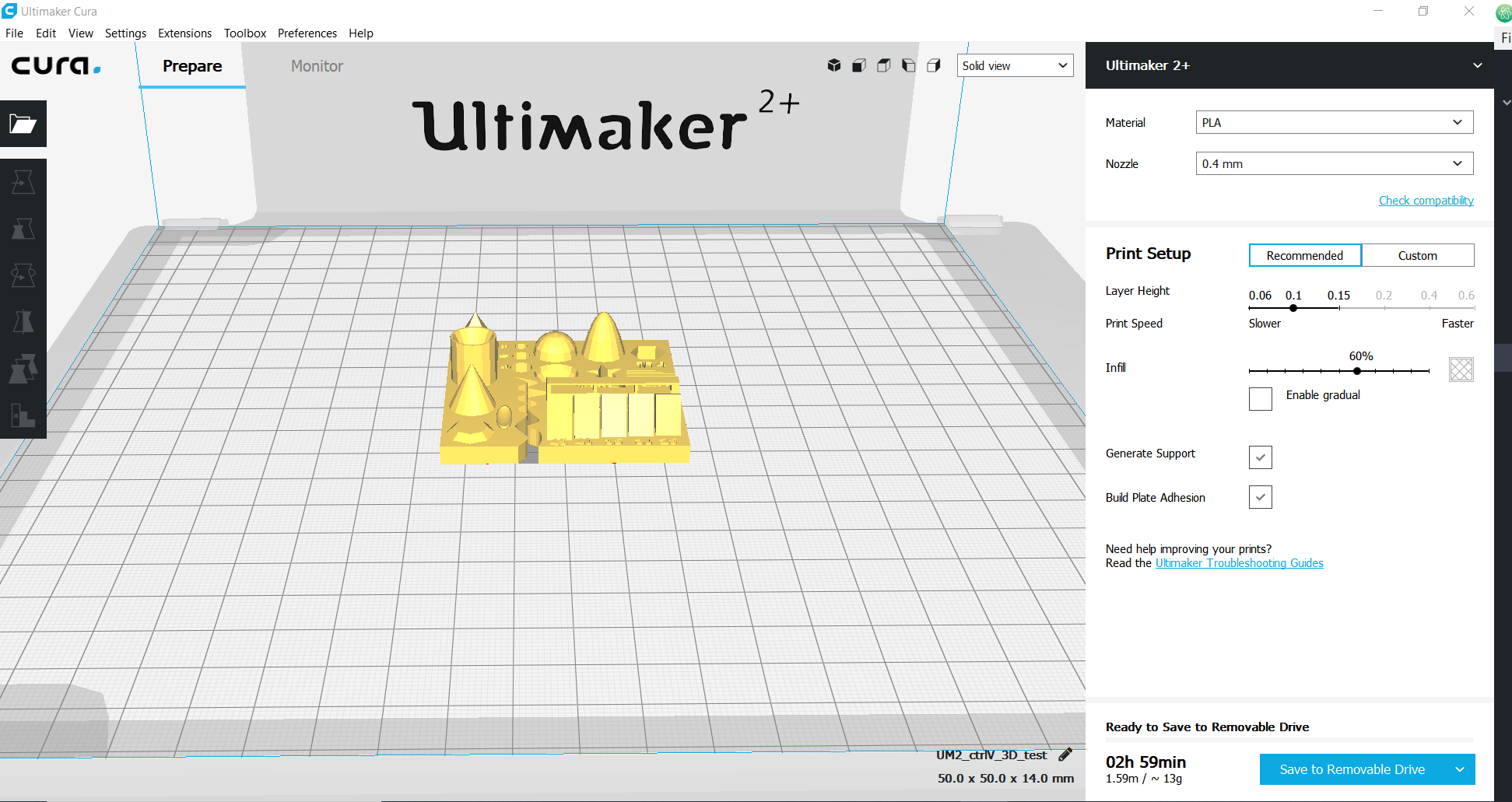
In case some are wondering why I decided to use two different machines from the same manufacturer. It is easy to assume that they should have the same quality, but I am not leaving anything to assumption. From my observation, there is a little difference in the time it would take to print the same object with the same parameters on the two different printers. Ultimaker 2+ will take almost 3 hours to print, while Ultimaker 2 Extended+ will take about 2 and half hours. This variation alone is a reference that such test should be done.
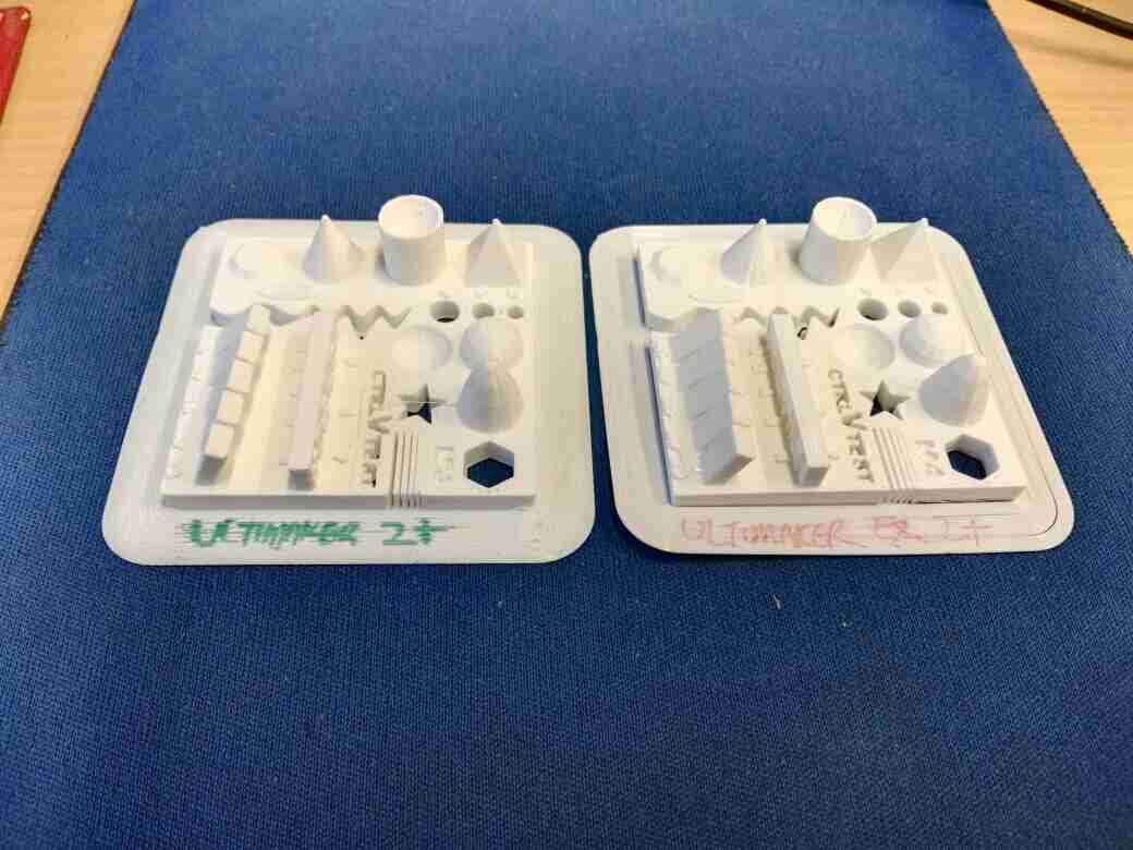
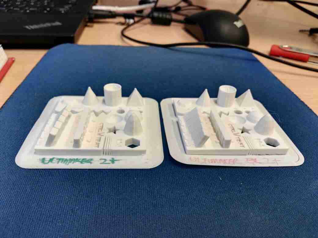
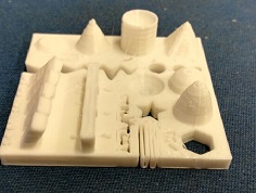
From the two Ultimaker 3D printers, everything seems to obey the design rule.
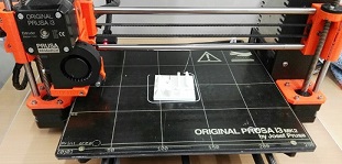
Prusa
Below is the picture of the printing of the design file on Prusa i3.
Fab Lab ENIT
For the group assignment,we want to test the 3d prints to learn how to use this technology and also to test the machine performance. So first we use Raise 3D N1 printer and ultimaker 2.
For the first test with Raise 3D N1, we used a design from thingiverse and printed it to understand the different prenting parameters. This is the Test file.
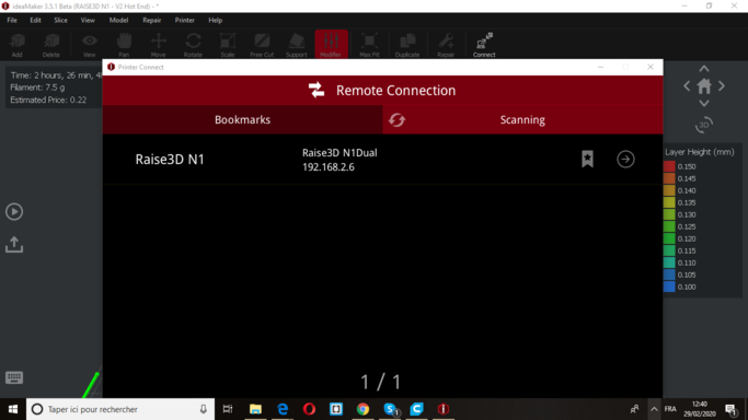
We also use the ideaMaker as a software to set the parameters, in the following pictures I will detail what we did:
1- Import file from your computer, click on the import button.
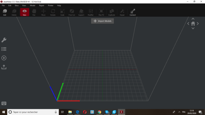
2- Choose your file.
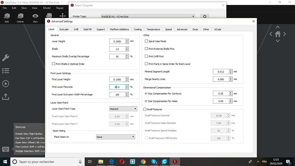
3- Modify the layer parameters : set the height of the layers to 0.1mm and the first layer height to 0.15mm
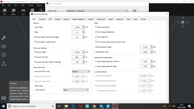
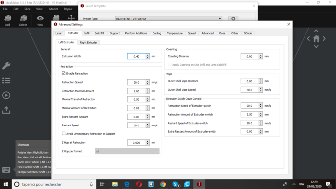
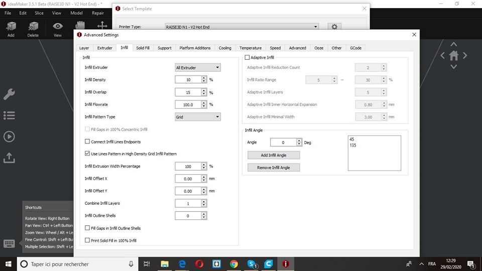
4- Since Nozzle diameter is 0.4 mm the extrusion width has to be changed to 0.4mm too. Modify Infill density to 10% and infill pattern type to Grid
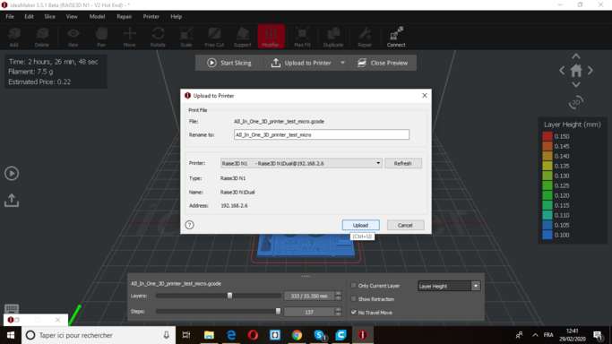
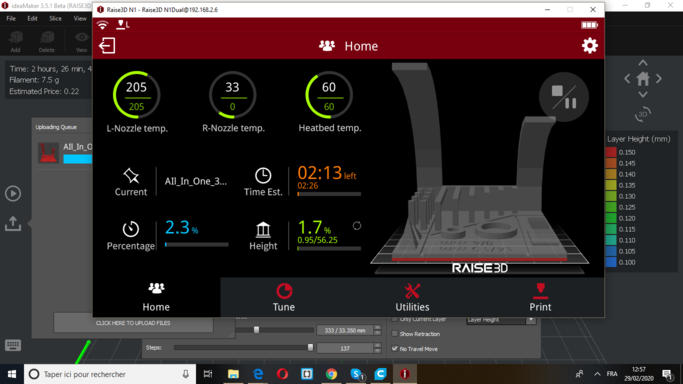
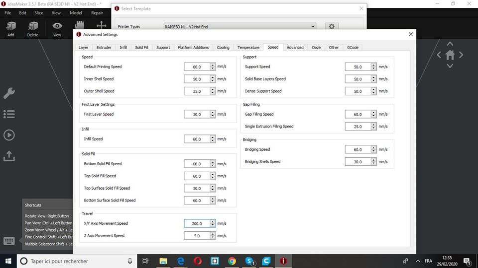
Several other optional parameters have been modified during this assignment group. After we were done, we connected my computer to the printer (it was really cool, just open your printer and control it from your desk).
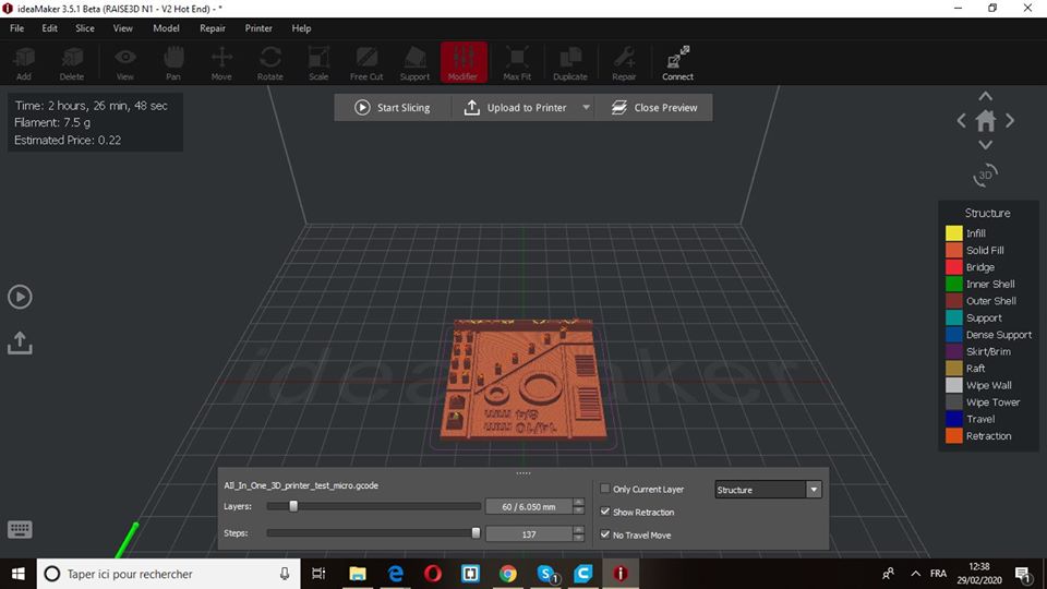
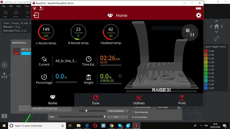
When the download is finished you can see your part and its information indicating the printing time, the current printing level, and the temperature of your printer …
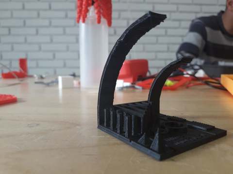
This was our first test , you can see that there are defaults so it is necessary to choose the parameters well.
To test the different printers, we have printed first model by the Raise 3d n1.
Raise 3d n1 propreieties
Print technology: FDM (FFF)
Build Volume (WxDxH): 8x8x8 inch / 205x205x205
Layer Resolution: 0.01-0.25 mm
Filament Type: PLA/ PLA+/ ABS/ PC/ PETG/ R-flex/ TPU/HIPS/ Bronze-filled/ Wood-filled
Printing Surface: Buildtak
Heated Build Platform: Yes
Enclosure: Yes
Nozzle Diameter: 0.4 mm (0.016 in)
Nozzle Working Temperature: 170-300 ℃
Number of Nozzles: 1 (standard) / 2 (optional)
Printing Speed: 10 ~ 150 mm/s
Moving Speed: 150 ~ 300 mm/s
Positioning Accuracy: XY-axes: 0.0125 mm, Z-axis: 0.00125 mm
To do this, we’ve used a file available on thingiverse
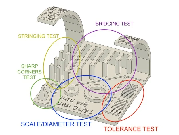
This article explains what should be measured as pointed below:
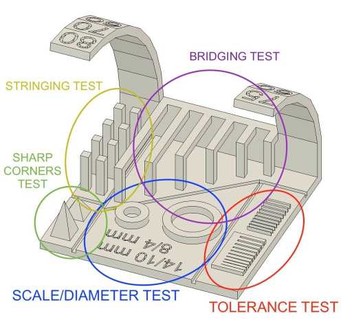
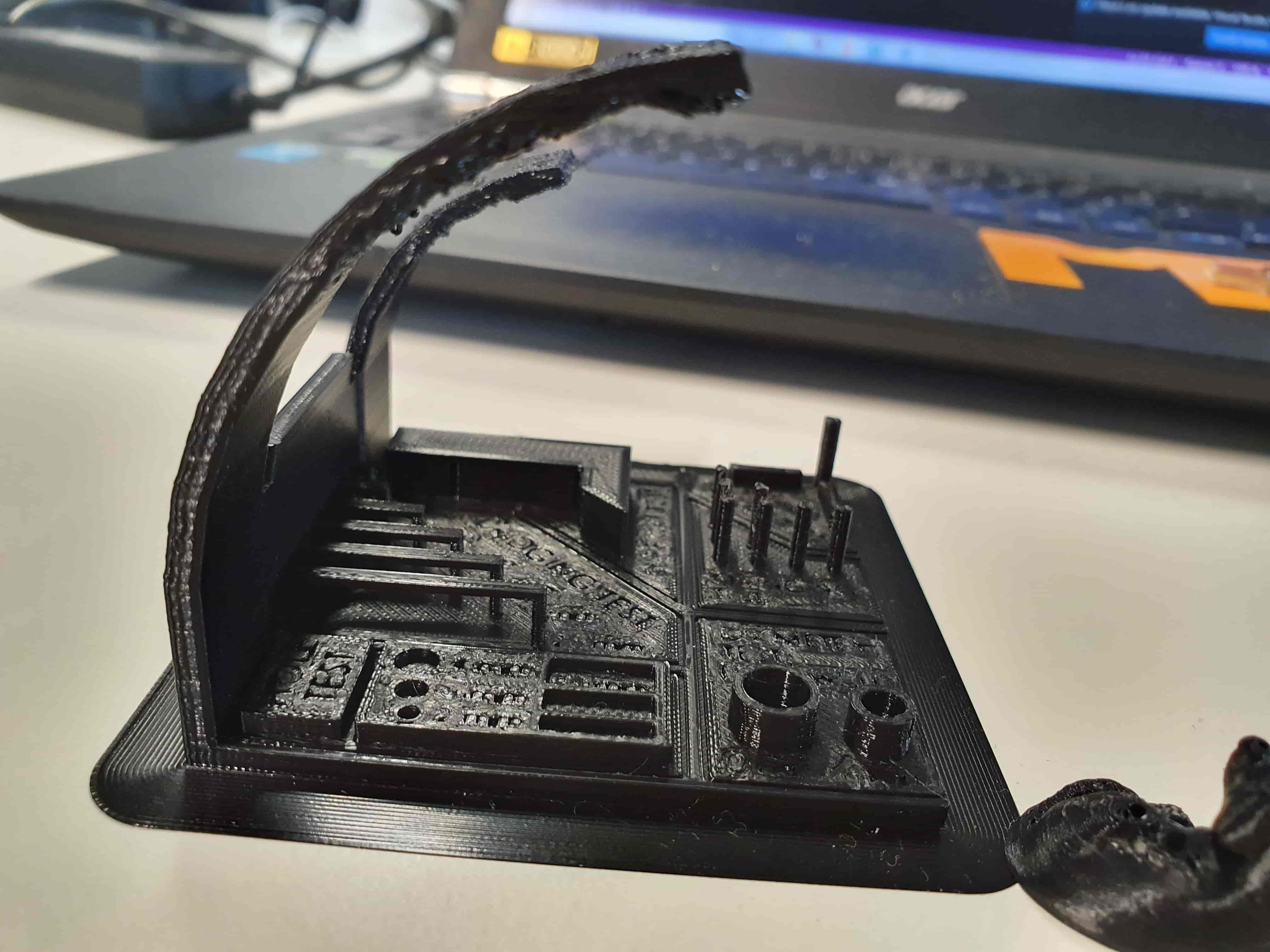
bridging test
Bridging is your printer’s ability to print a layer between gaps in lower layers without support, essentially printing over thin air, creating a “bridge”
Stringing test
3D prints sometimes show small strands of plastic on places where the printer shouldn’t print and the print head must only travel from one place to another. These unwanted strands of plastic is called stringing
Tolerance test
It describes how much deviation from a particular value is expected or acceptable. In 3D printing, like any other manufacturing process, machines have specific tolerances. This means that prints may slightly deviate from the actual dimensions. A tighter tolerance indicates consistently higher dimensional accuracy
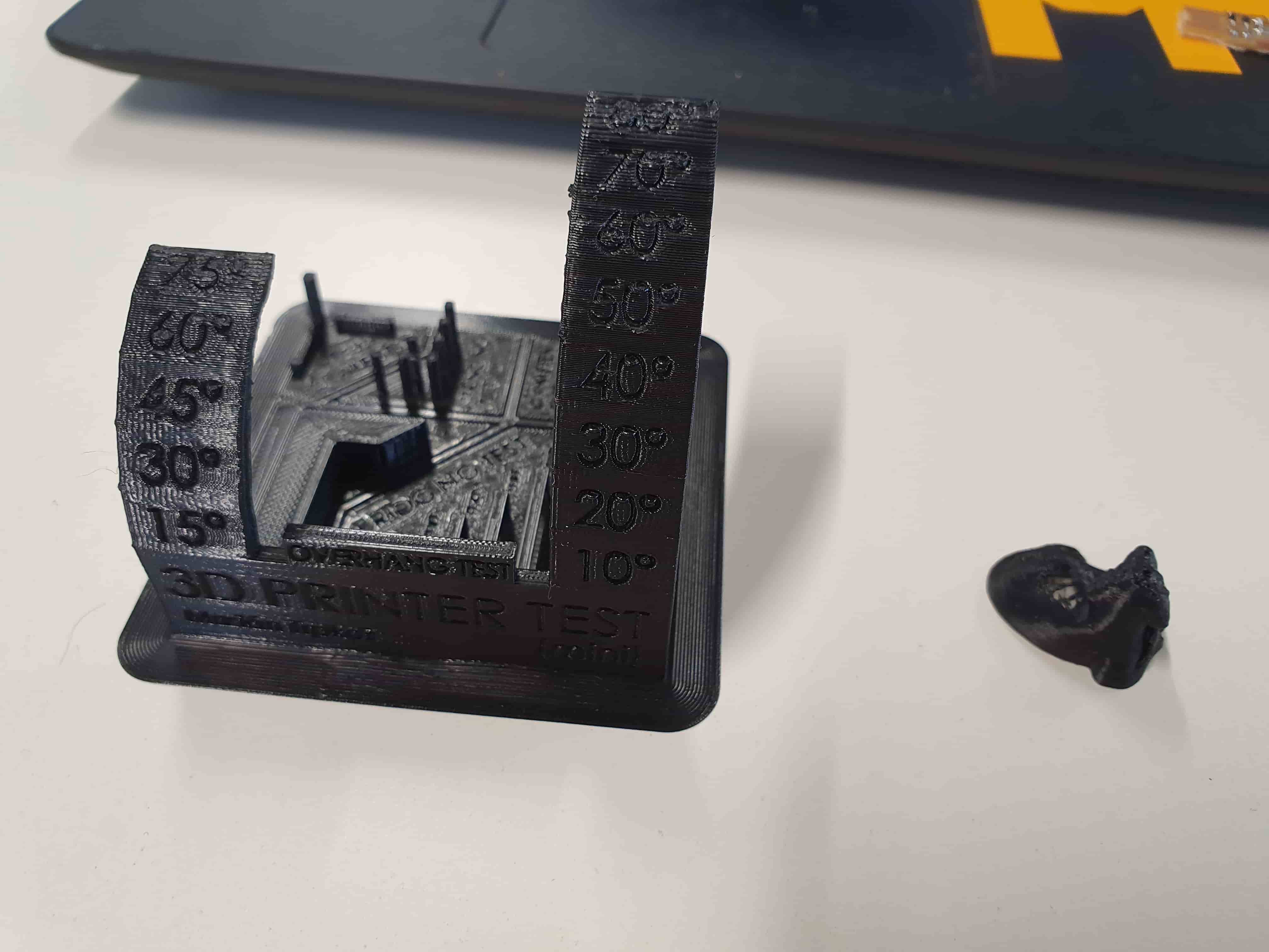
Overhang test
In general, when your model has an overhang or a bridge which is not supported by anything below, you may need to use 3D printing support structures to be able to 3D print it.his test aalows us to define the ability of the 3d printer to make overhangs without support .
To test the design rules of our 3d printer we have fixed the following measurements
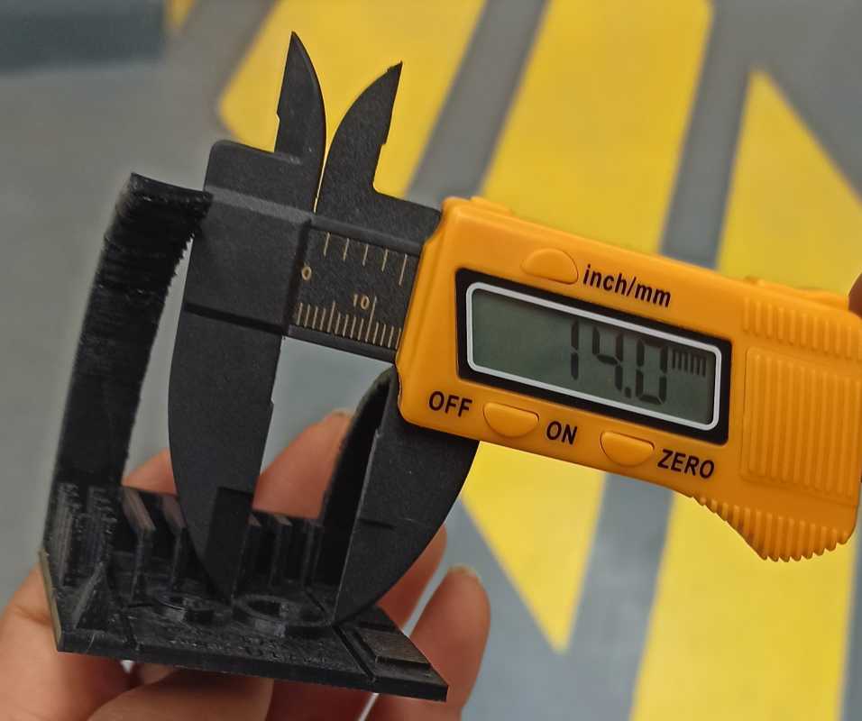
 *  Hole size: 2 holes (8/4/mm) (14/10/mm)
 * Tolerance test : 0.05/0.1/0.15/0.2/0.25/0.3/0.35/0.4/0.45/0.5mm
 *  Bridges length : 2/5/10/20/15/20/25 mm
 * Overhang : 10°/15°/20°/30°/40°/45°/50°/60°/70°/75°/80°
Slicing settings
Layer height: 0.1mm
Shels: 1
Infill: 10%
Speed: 60mm/s
Nozzle temp.: 205
Bed temp: 60
Material: PLA
Printing process
For the printing process, we will need to import the .stl file with the proper software, In our case we used idea maker for (Raise 3d n1).
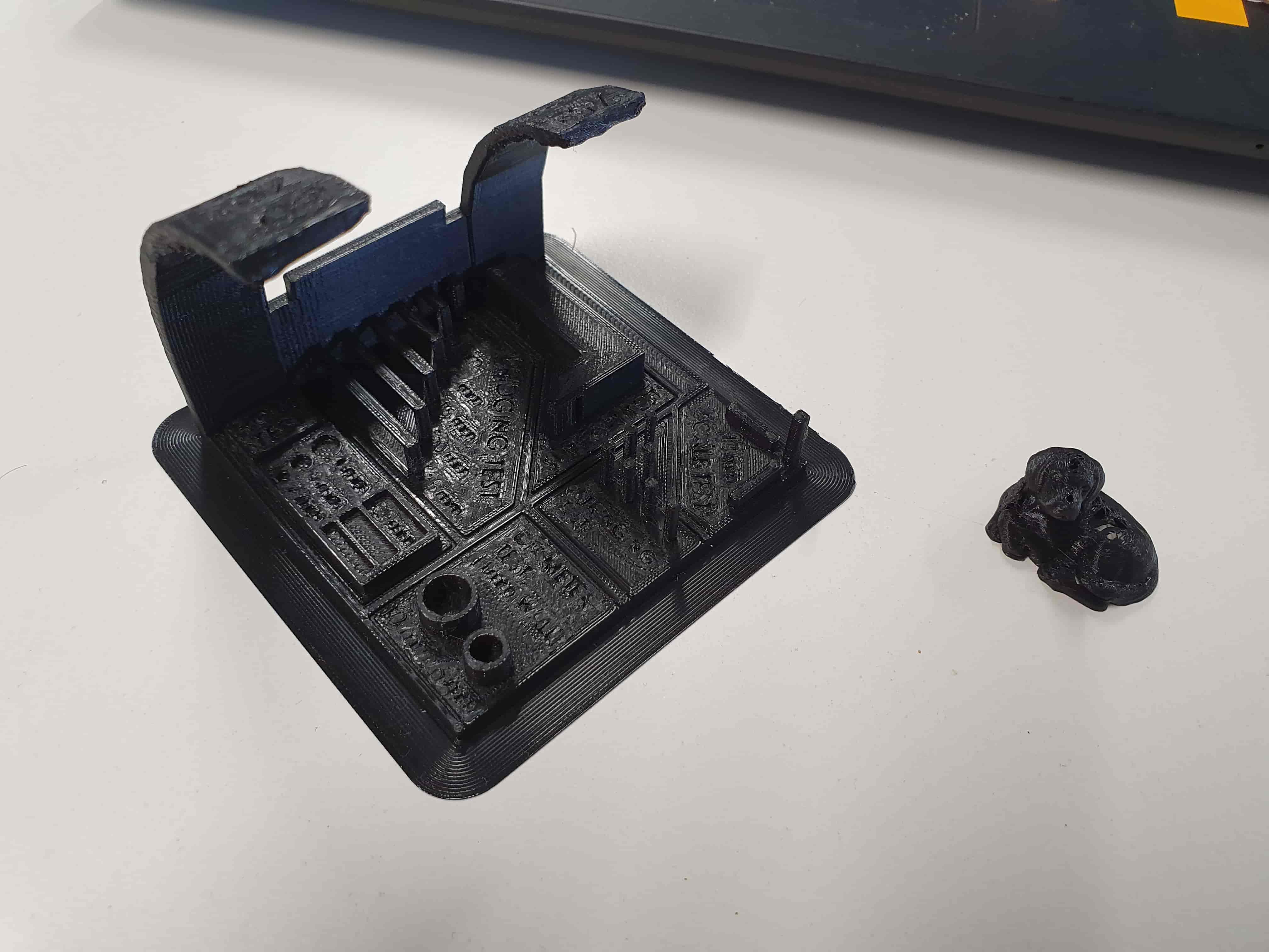
Testing results
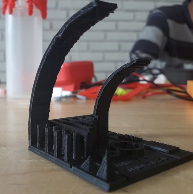
These are the results of the testings:
Raise 3d n1
Results
Overhang : Up to 45 º
Stringing : No unwanted strands of plastic
Bridges: We got perfect bridges up to 25mm without a support
Tolerance test: We coudn’t have same dimensions , however we had a similar tinny parts measured around 0.4mm . It’s explicated by the fact that the machine is able to make multiplication measures of the nozzle dimension (0.4mm)
Scale test: We obtained same dimensions as measured