MakerSpace - Electronic Design
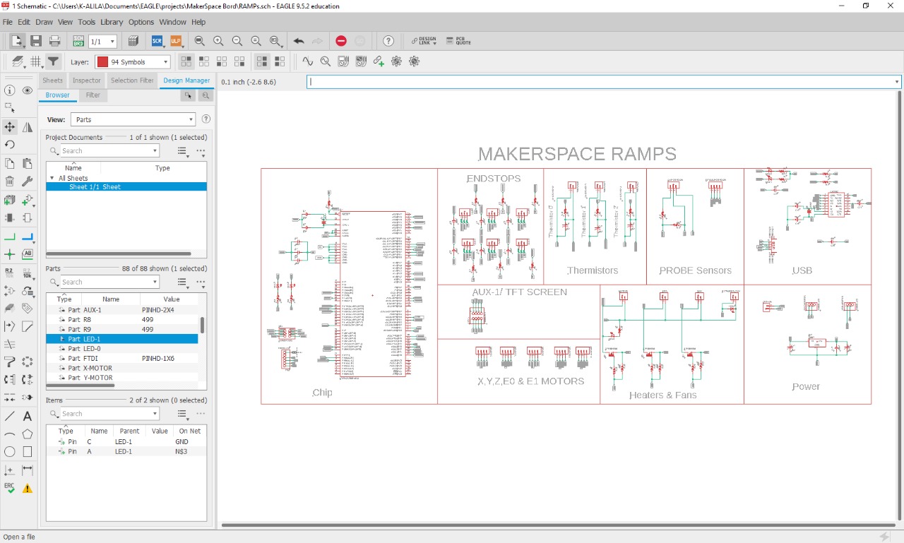
I’m designing my first complexe board which is the controlling borad for the project. The Ramps board. My board is orriganally based on the open source ramps 1.4 model and I am also Folowing the FabRamp board. This board was designed by my freind Hashim Al Skkaf who was a fabacademy student 2017 and he is now the FabAcademy instructor at Fablab UAE
Download files: Ramps Board, Stepper Board,Ramps Schematics, Stepper Schematics
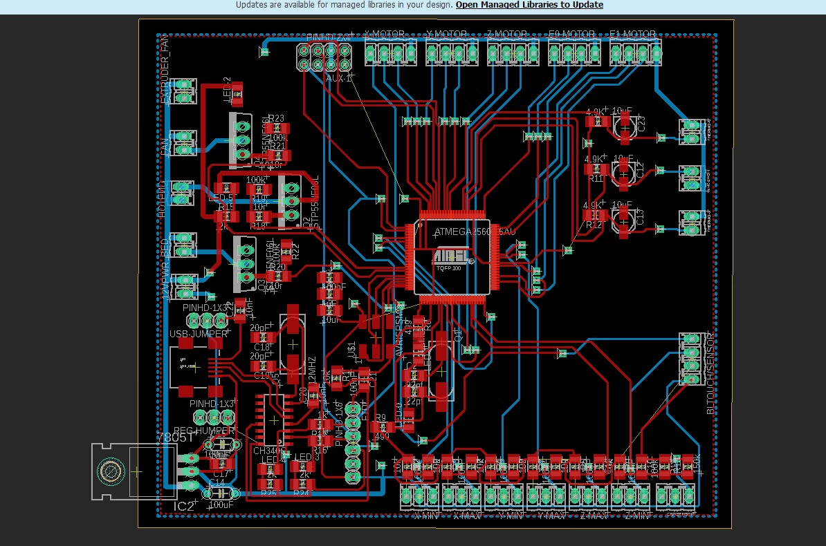
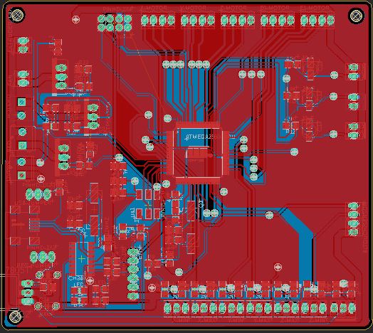
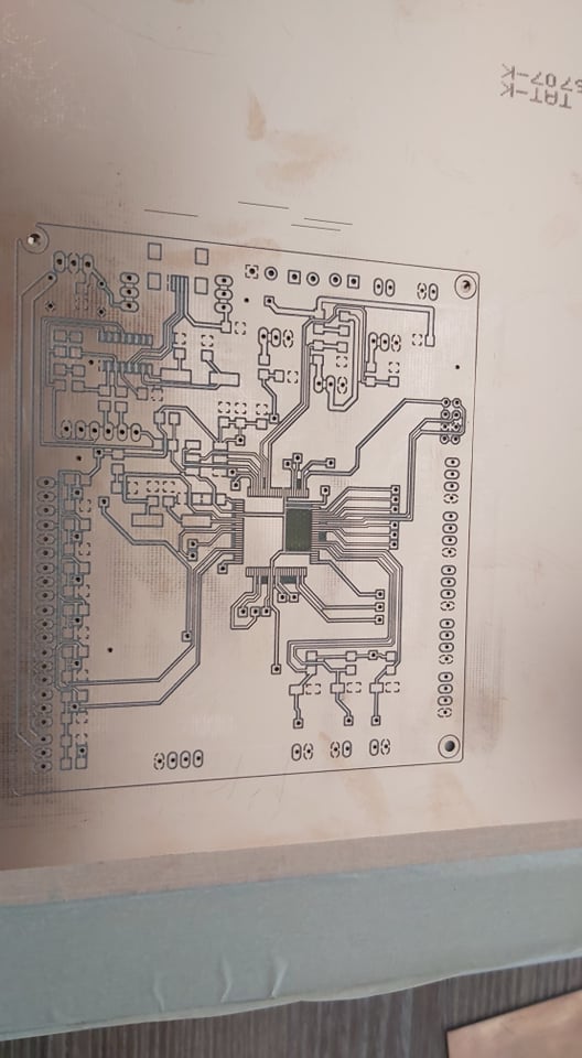
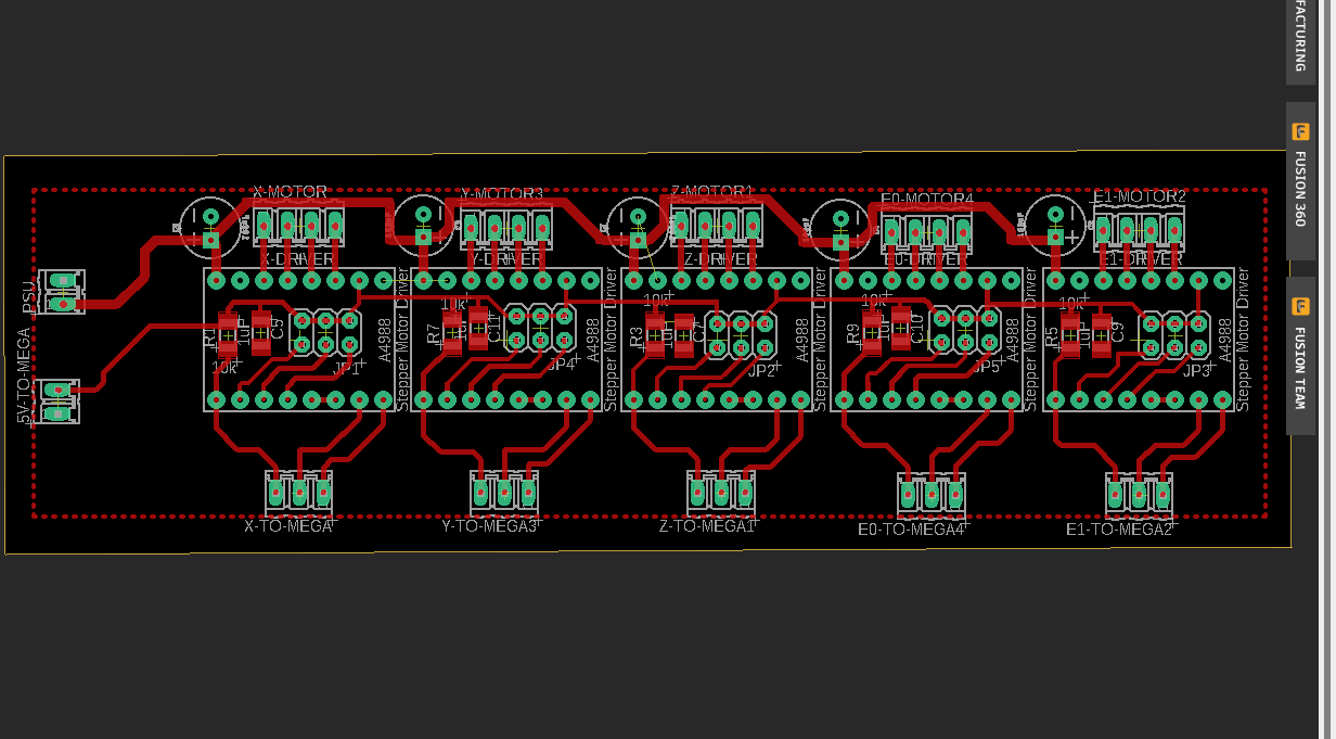
RampsBoard
During this week I’m designing the board for my final project. [Work In progress]
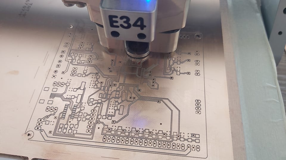
Manufacturing
Usually for pcb milling i use my open source cnc or the cnc for wood in our fablab, For this board I beed it to be very precise because I have to mill the Atmel 2560 footprint processor. In this case, I went to anther fablab who have a high precision cnc for pcbs LPKF cnc

For this machine, we command & generate the g-code using the machine software. It works with GERBER file generated from Eagle like shown in electronic production week

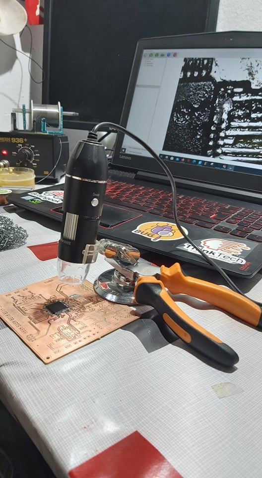
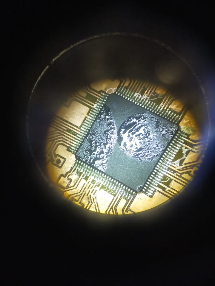
To guarentee the qulity and the trace depth and width, we are using the machine microscope to adjust and set the machine parameters.

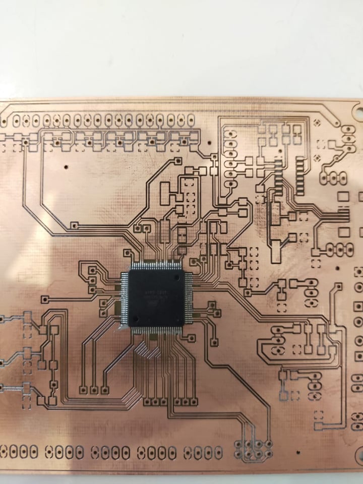
Results:
 .
.
Assembling
The processor was the most dificult componnent to solder, I already dameged two boards, so in this case I used a microscope to help in soldering. the processor should be the first cmponent to solder and then starting from the vias to the rest.
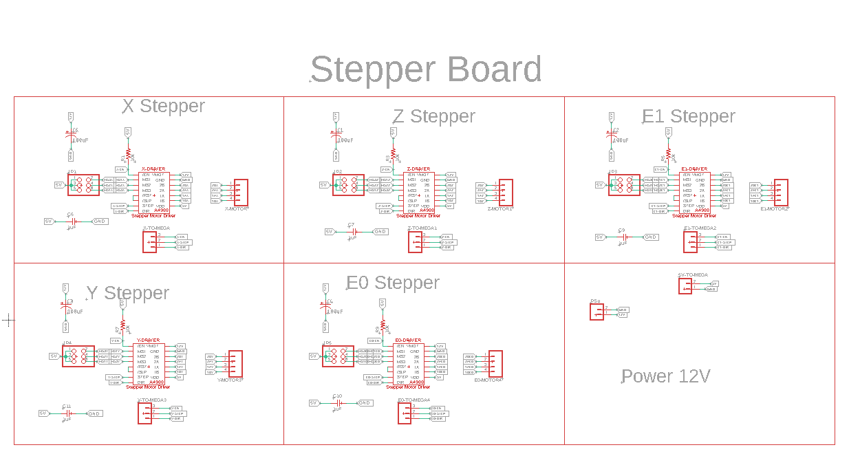
Stepper Board
I also designed the stepper board seperatly to make the wiring simple and the manufacturing easier.
Tools Board
In the previous version, the machine has wiring and cabels issues. Each tool has it’s own cable and it makes the wiring really complex.
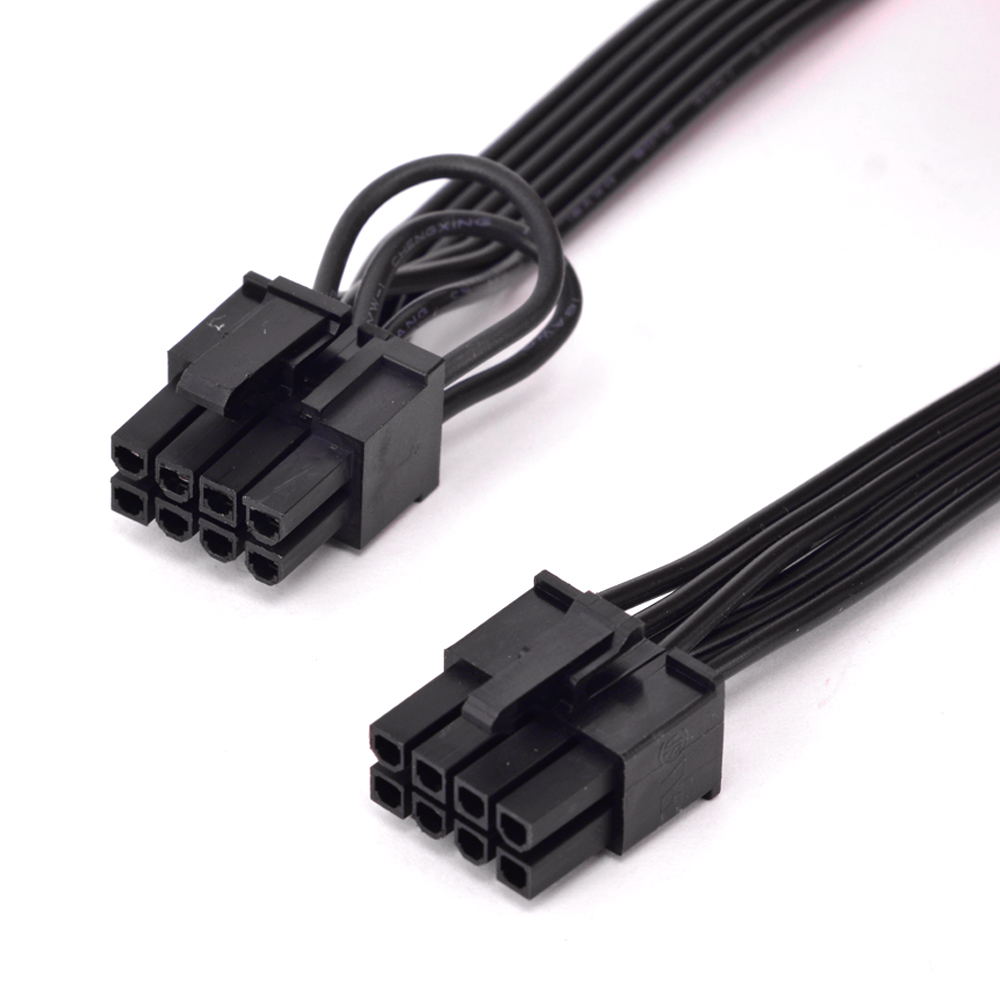
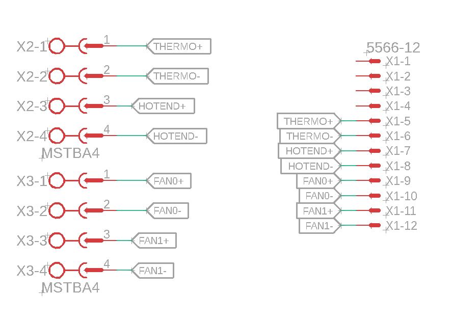
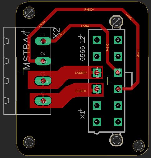
The solution I found is to make a unique cable for the 3 tools at the same time. So I designed a scketch to indicate the needed wires for each tool and how to wire them with 55666-12.
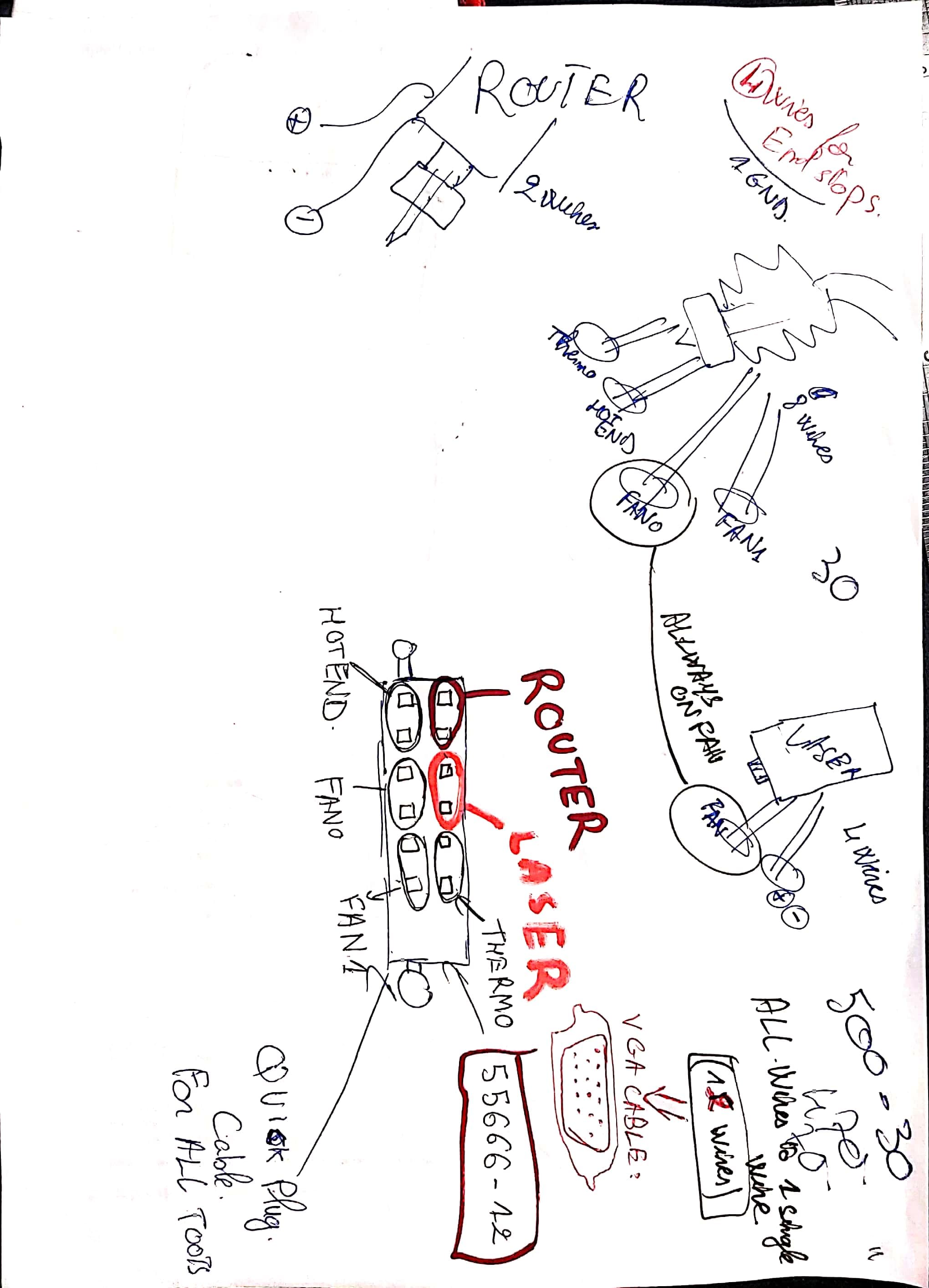
I chose 55666-12 because it is usally used in the Computer PSU and supports high voltage and curent
3D print Tool board
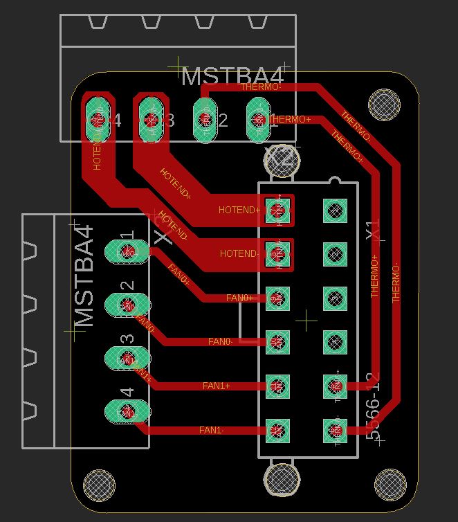
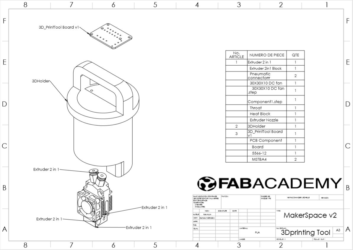
As shown in the detail every tool will be equiped with its special board.
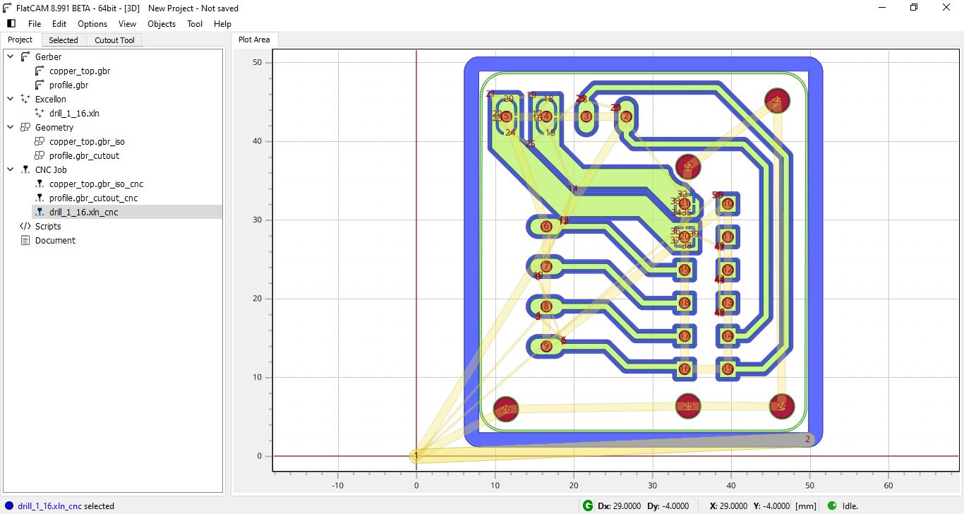
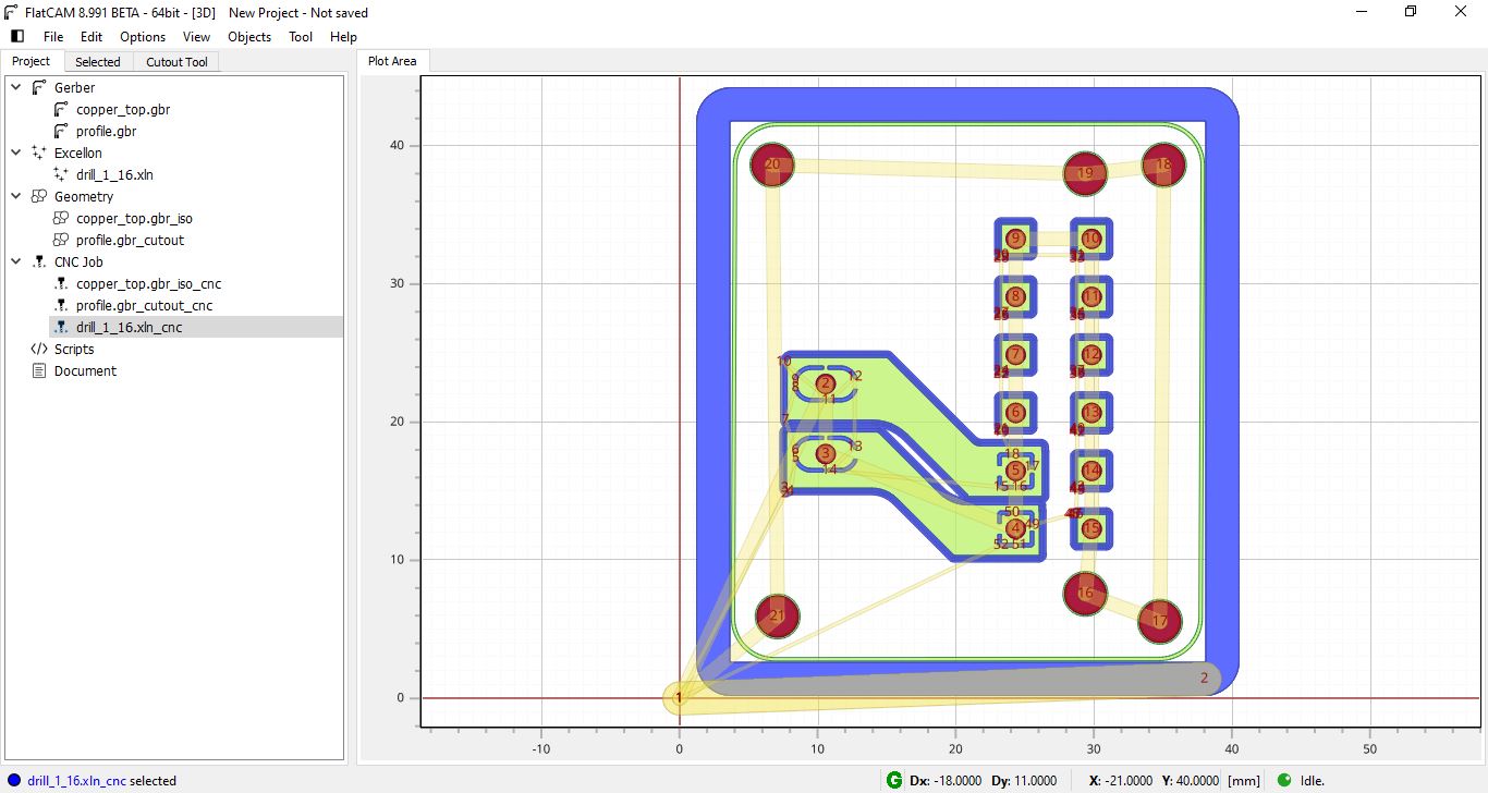
Fabrication
Using as usual FlatCAM to generate the gcode and make the board.
I am using this time a 0.2mm 30° 3.75mm V bit
Laser Tool board

Fabrication
CNC Tool board
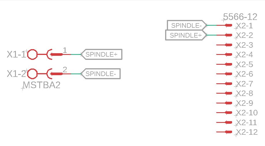
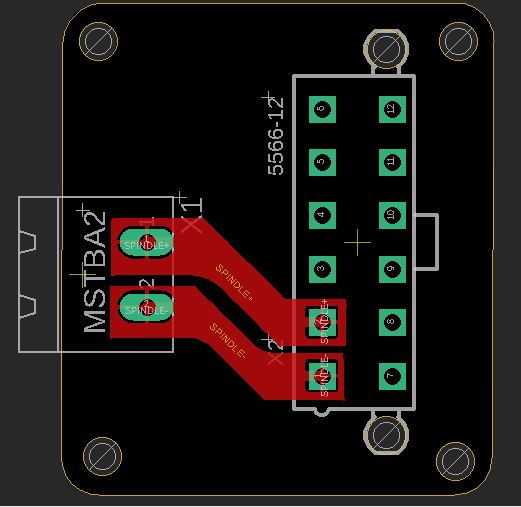
Fabrication

MakerSpace Wiring


I couldn’t make an electronic box for the elctornics compact and attached to the machine before the presnetation so I made a big one to make it fast and test MakerSpace. In the video, it s not clear that i am using this box because i hade it to hide also this mess :)


Testing
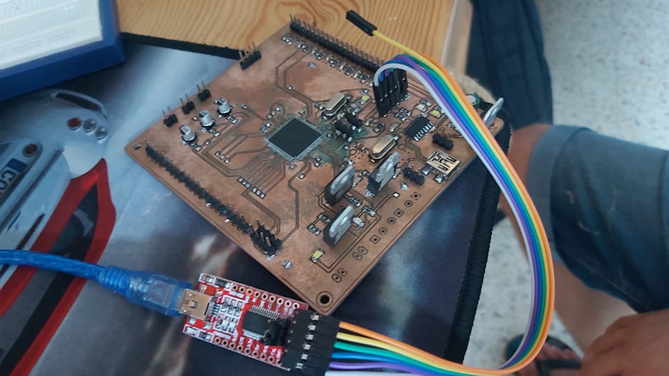
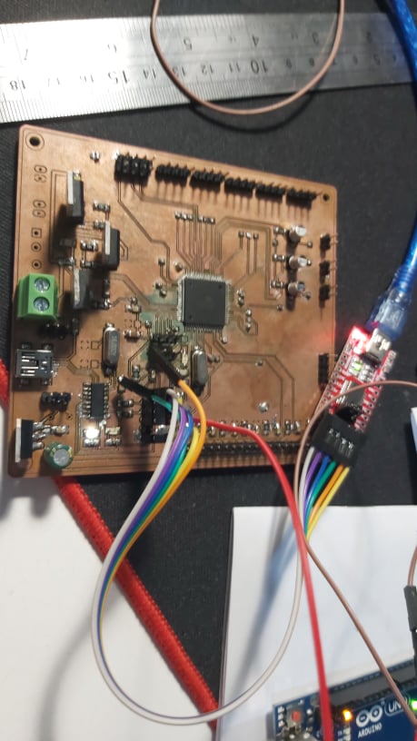
After soldering all the board, I wanted to test and see if my soldering and connection are okey or not.
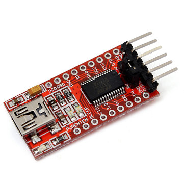
Like in electronic production week, I used Arduino as ISP to program the board. I burned the boot loader successfully, and it was a promising start. After that I used an FTDI programmer to comunicate with the board via serial communiction and test if the ramps respond.
For the wiring , I used my extra pins for ftdi because I am using a CH340C processor for this.
Connections :
-
DTR –> DTR
-
RX –> TX
-
TX –> RX
-
Vcc –> Vcc
-
Cts (Not connected)
-
GND –> GND

- Testing stepper motor:
- Testing extruder and LCD: