Mechanical and Machine Design @ Kamp-Lintfort
Students:
William MegillKai Tiedemann
Hannes Jaschinski
Gerhard Mattissen
The objective this week is to put all of our learning together into designing and building a workshop machine.
Embroidery machine
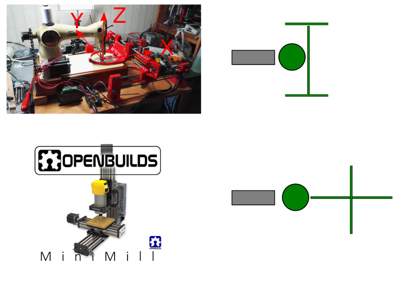
The team decided to build a CNC embroidery machine using my daughter’s sewing machine as the central core. The idea came from inkstitch.org. We started from a photograph from their website, but designed our own machine from scratch.
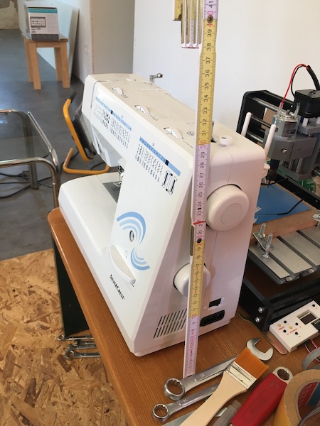
Here is my daughter’s machine (with a ruler for scale):
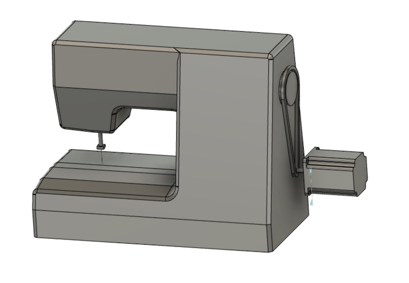
Job 1: CAD-ing the sewing machine
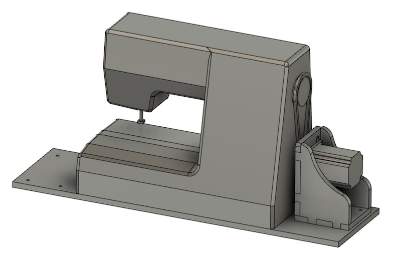
The first step was to create a Fusion360 model of the sewing machine. Rather than get fancy with a 3D scanner, since there were only really a few places where the exact dimensions matter, I just relied on the ruler and tried to be precise to within about 0.5mm.
The machine itself presented no huge problems to Fusion. I drew the stepper motor from the spec sheet provided by the manufacturer. They are basically just blocks with lots of cutouts and fillets.
Job 2: z-transmission
The sewing machine is fully functional, but it is borrowed, so we didn’t want to hack into its controls to use its own motor to power the needle. Instead we chose to connect a stepper motor to the handwheel and drive the mechanics of the machine completely externally. Because there is quite some force to be overcome even with all of the mechanical advantages built into the machine, we decided to use the largest stepper motor we had available, which is a Nema 17 42-75 that can deliver 65 Ncm of torque. Though that’s a significant improvement over the little steppers we selected for the axes, we felt it would still not be enough to rotate the sewing machine’s internal mechanism.
Since we had to add a driving gear to the system anyway to turn the hand wheel, we decided to design in a mechanical advantage gearbox using some bicycle gears that were available in the lab. The gear ratio is 15:36, or a little better than 1:2. We’ll need to spin the big stepper quickly, but we shouldn’t have any trouble with stalling.
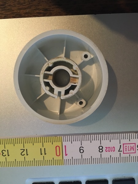
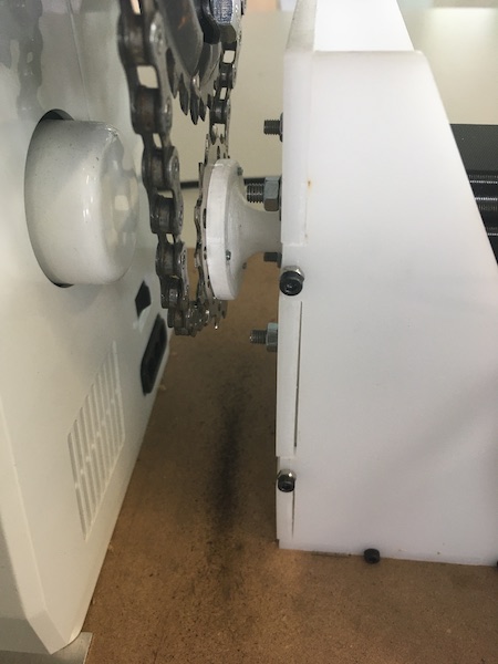
The parts of the transmission and the sewing machine’s original handwheel are shown below:
![]()
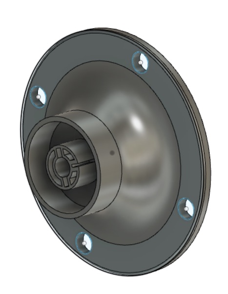
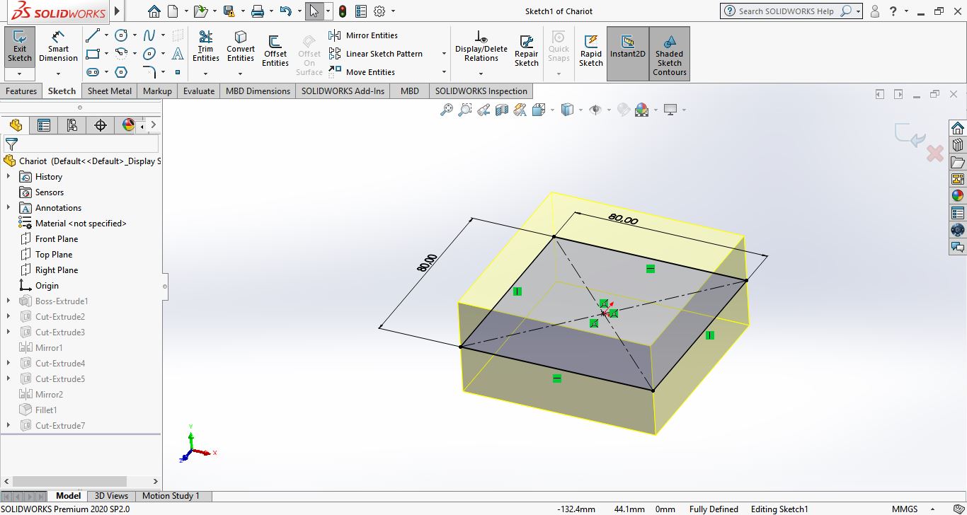
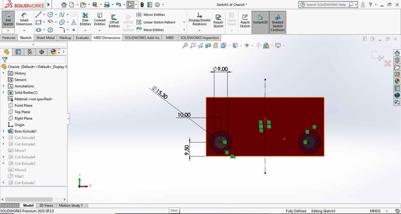
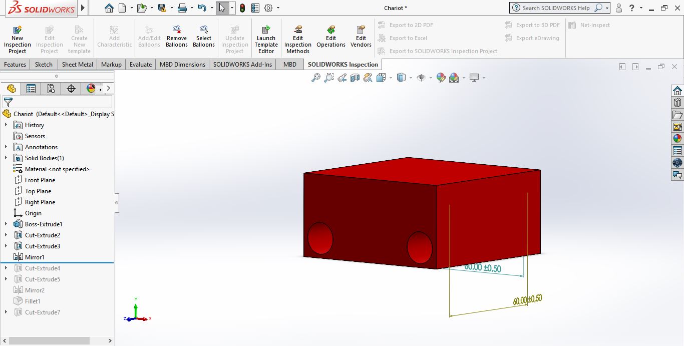
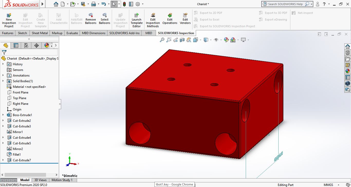
I didn’t want to destroy my daughter’s handwheel, so I measured it carefully, inside and out, and made a new wheel to hold the large bicycle sprocket. The original wheel and the CAD for the new sprocket holder are shown below.
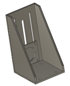
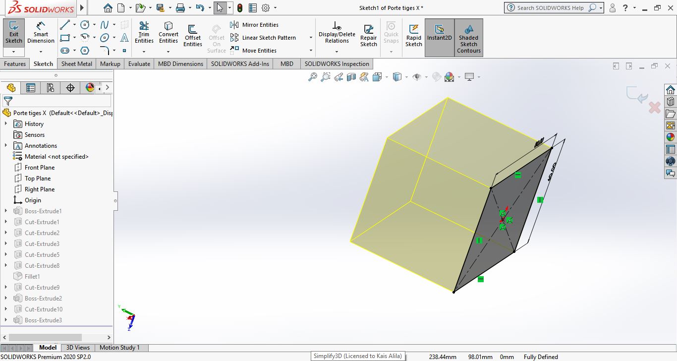
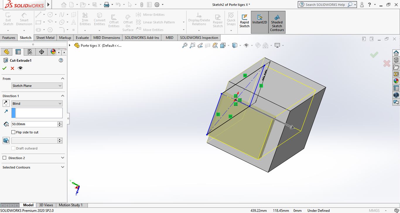
Job 3: z-motor bracket & wheels
I then designed a bracket with a slider face for the motor. The idea was that the slots in the faceplate would allow us to push the motor down to tension the belt, whereupon we’d tighten the bolts on the faceplate. The assembly looks like this:
The belt in the picture was made using projections in the plane of the gears after the machine block and motor had been “joined” to the base plate (not shown). I created a joint between the handwheel on the sewing machine and the needle, though that will need revisiting later, as it is a rack-and-pinion joint rather than a sinusoidal one.
Job 4: The CAD assembly
Fusion 360 made our lives easier with its integrated and online PDM system. It wasn’t the fastest of systems, but it did mean that we could each work on our own part of the project then combine them when we were done. There were a couple of clashes where people were working on components within the same assembly, which resulted in some duplication of effort. There is a balancing act to be lived between the team-work friendly placing of all components in the Fusion browser and the more convenient editing capability when the parts are directly in the local assembly file. In future, we’ll have to agree a working protocol to make that all smoother.
The team did their various parts, and it fell to me to integrate them all into a single assembly to make sure that all of the dimensioning was correct. That job ended up being a lot more time consuming because of the different approaches everyone took to designing their parts, which meant that I couldn’t easily adjust the various lengths. Nothing was done parametrically - each had drawn his parts to the dimensions he was given and then simply brute forced his way with multiple sketches on multiple faces, with extrusions and cuts to make the part work. The end result was a part that was functionally correct and exactly what had been specified, but modifying it to make other parts fit was a nightmare that went on till 3 in the morning.
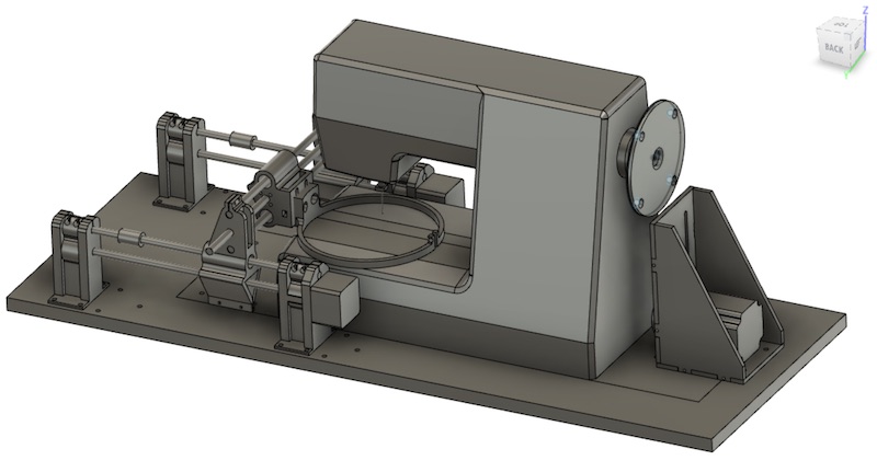
In the end however, it did all go together. This is what it looked like at 3AM that morning:
When everybody else got up, it took a few direct hits in the design feels. There were little things all over that needed fixing. There were essentially four problems:
-
The dimensions needed to be fit around the actual sewing machine to ensure there would be enough clearance. That required the corner posts all to be adjusted in height, but as they’d been redrawn with a parametric length and grounded sketches, that was easy to do.
-
All of the various openings and holes had to be enlarged to take into account the effective “kerf” of the 3D-printer, which was said to be about 0.2mm.
-
There was a worry about overhangs and infill/support material. This required some fairly significant redrawing of parts to create as many flat sides as possible from which to print.
-
A new guiderail had to be included on the y-axis, to take up the torque that we expect will be generated by the needle going through the cloth. Although the ring is being designed to be simply supported on the working are of the machine, nothing is level there, so the torques are likely to be significant. Furthermore the y-axis driving “nut” consisted of two rather flimsy 3D printed top-hats, themselves connected to the mechanism with 3mm bolts. All of that just said, “add another guiderail”. That introduced all kinds of dimensioning and clearance problems, but all was solved by the end of the day.
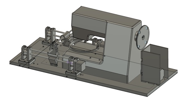
The final assembly, after all of the fussing, looks like this:
Job 4: Printing/Cutting parts
Once the design was complete, we could start producing the parts.
The Z-motor mount parts were cut out on the Epilog laser cutter from a block of POM we happened to have lying around. The mount assembly is shown here:
The final assembly came out like this:
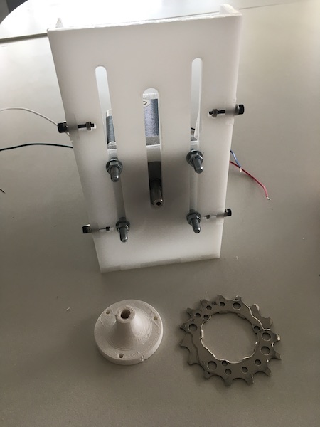
The lower sprocket and drive wheel are also shown in the picture.
We 3D printed the rest of the parts out of PLA using several different printers.
The upper sprocket holder was 3D printed on the lab’s Ultimaker, which gave us no issue (but man is it easier to use than the previous version I was introduced to two years ago!).
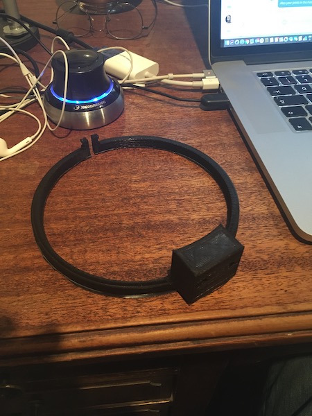
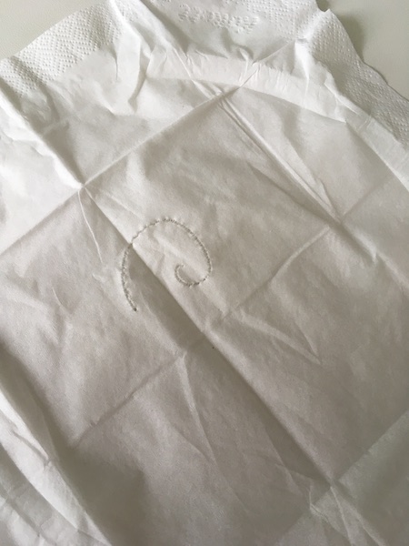
The Ultimaker also had no trouble printing the embroidery loop:
We tried to print the rest of the mechanism parts on the lab’s Felix Tec4 printers, but for some reason they failed overnight. Luckily we had predicted there would be trouble, and so I printed the two X-sliders on the Ender-3 in my home lab, along with a backup of the embroidery hoop. They turned out beautifully.
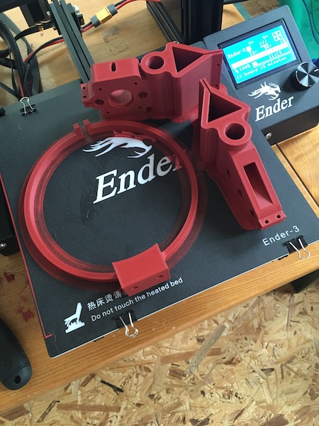
The only bummer was that I miscalibrated the z-axis too close to the bed and the brim ended up smeared too thinly on the bed, with the painful consequence that it’s taken several hours of scraping to restore the printer bed to use…
Once the parts were printed, the machine was assembled and powered up as described by the other team members. It came for a visit to Qualburg over the weekend where I got to try out the software control to make it work.
* Split here.**
Job 5: CNC control of the x-y axes
The instructions I was provided were to install grbl as the driver for the Arduino- and Satchakit-based stepper motor controller, and then to use CNCjs as the g-code interpreter. It works very nicely, as does the Candle interface that came with my Sainsmart CNC-mill.
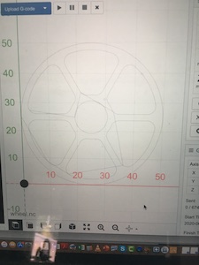
To test the x-y function of the axes, I used the example CNC cutout that came with my mill, of a simple wheel. I then removed the embroidery ring and zip-tied a pencil to the y-traveller before starting the job. Here’s the little machine getting started.
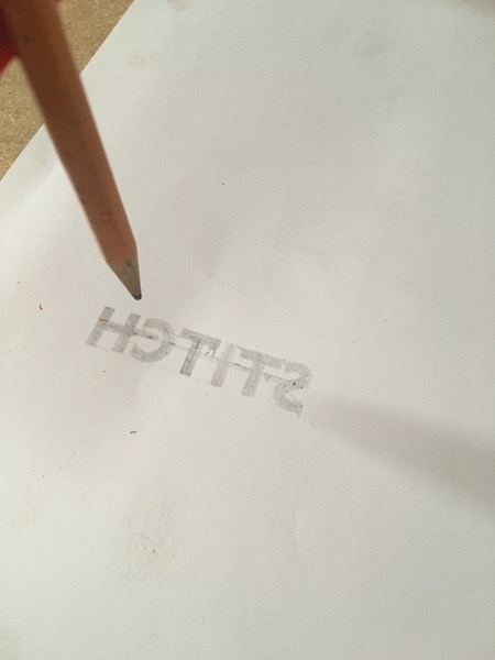
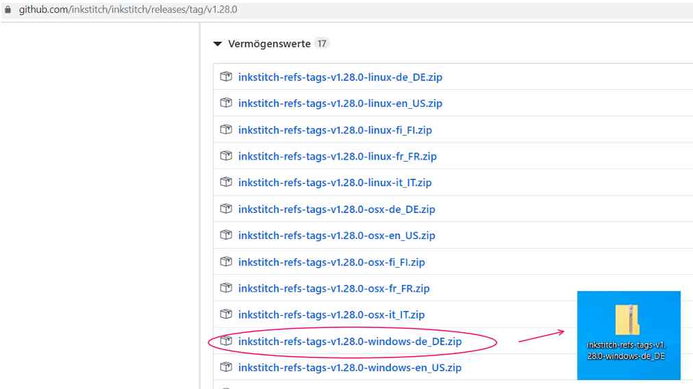
After testing that the CNC-controller worked with the x-y axes, I downloaded the extension called “inkstitch” from this website which creates the g-code required to run an embroidery machine directly from drawings in Inkscape. I tested one of their example files using the pencil connected to the y-traveller to confirm that it would all work:
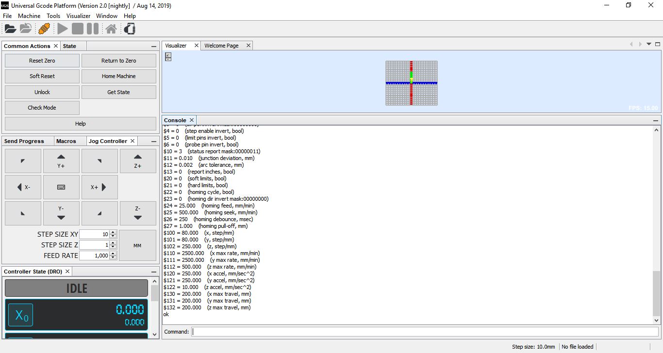
It was painfully slow, so I paused the CNCjs job and increased the speed and acceleration settings as shown below in the console window of CNCjs as the Arduino is first powered up and connected to:
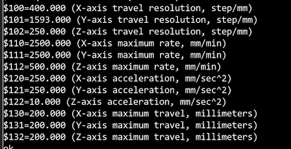
The x and y speeds had been set to 500 mm/min, and the z one to 50 mm/min. Accelerations were 50,50,10 mm/sec2. I increased the accelerations to 250mm/s2 and the speeds to 2500mm/min. That made a big difference, but it might also have introduced an error, as one can see in the picture below, where the Inkstitch “needle” or “spear” has been drawn in the middle of the lettering, rather than above it.
Job 6: Assembling the machine and test
The machine came together nicely. A 16mm MDF board was cut to size and holes were milled to fit both the x-y apparatus and the sewing machine. We then placed the motor mount such that the driving gear was aligned directly below the handwheel gear, marked the holes and drilled them out. All that remained was to split the chain and set it to the right length.
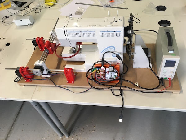
The following day, we fit the chain and powered everything up. Here’s proof the machine runs!
Job 7: CNC calibration of the needle
The next step was to set up the z-axis with the sewing machine. We set a piece of paper under the needle, between the tip and the strikeplate, then zeroed the CNCjs position. Then we stepped the z-axis through the whole cycle until the needle was back in the same position, just tickling the paper. The measurement was 30.65mm.
The software (Inkstitch) we plan to use to create the G-code puts the fictive z-axis through a 5mm motion which should take the sewing machine needle through one complete cycle. In order not to require the eventual user to fiddle with any of the default settings in Inkstitch, we decided to calibrate the machine to suit the 5mm steps.
The GRBL driver was set when we did the needle test with a z-resolution of 250steps/mm. That times the 30.65mm and divded by 5mm/cycle gave us a calibration constant of 1532steps/cycle. We tested that and found it to be a little over 360degrees, so we scaled back to 1547 experimentally. We also changed the sign of the z-axis in GRBL using the $3=4 command. (The 4 in binary is 0b100, with the three bits indicating that the z-axis should be negated, while the y and x axes should be left as they are.)
Job 8: Smoke test
Now it was time to run the machine with a test from Inkstitch. We created an “o” in Inkscape, ran it through Inkstitch, and saved the G-code. We started the machine and whooped with excitement as it did exactly as requested.
That is, until it broke.
Several things went wrong with the z-drive. The end result was that the chain jammed and then came off the lower sprocket, which by that point was precessing wildly around the drive shaft, having completely failed in its centre.
The cause of the failure was a perfect storm of little things:
- The nut holding the upper sprocket on to the machine had come loose from being turned both ways during setup.
- The lower motor unit wasn’t lined up properly parallel to the long axis of the sewing machine.
- The chain was too tight.
- The lower sprocket was driven only by a plastic square side in the centre hole, which broke due to the torque.
- It caught us by surprise.
The solution was to design a new lower sprocket, this time with a wider base to accommodate a nut through which a set screw could be threaded to hold the torque against the flat of the stepper motor drive shaft. The new part was quickly 3D printed and the centre hole was drilled to size (I’d have preferred to mill it exactly, but time was of the essence.)
With the new sprocket in place, the alignment all sorted, and the upper sprocket properly fastened, we fired up the system again, only to have it immediately stall. The quick-and-easy fix was to limit the maximum z-motor speed to 80 mm/min in the GRBL settings.
After all of the futzing, this was the end result:
We’re pretty stoked.
Job 9: “Spiral” development
The next step was to confirm that the CNC stage moved the fabric correctly into place for the needle to stab. This we tested by poking a spiral of holes a piece of tissue paper.
There were several challenges on the way to that output. The first was that we were asking the motors to accelerate far too quickly, so we used the $120 and $121 commands to limit their performance. This was particularly important when the starting point for the embroidery was a long way from the centre of the x-y plane.
The next issue took us a lot longer to sort out. Despite our $3=4 command, the z-axis would often start out backwards, then seemingly switch direction at random. After some careful debugging, we realised that the problem was occurring after we’d stopped the machine and restarted without first zeroing all of the axes. The machine was therefore first sending the z-axis back from whatever quite distant coordinate back to the “5” that was first commanded in the G-Code.
Once all of the bugs were worked out, we could start on making a final test piece. We threaded the machine, then clamped a new piece of cloth into the embroidery holder, and set it the task of stitching a spiral. Here is part of the process:
We discovered during the stitching that our z-calibration was a bit off, such that the x-y table would try to move while the needle was still in the fabric, so we had to stop from time to time to move the handwheel manually forward about a quarter cycle. Some minor changes to the $102 line will eventually fix that.
We also discovered that the foot of the sewing machine is an important part of the process. It is required for the upwards travelling needle to secure the knot in each stitch. Without it, the fabric simply distorts and the stitch is left loose. The solution was to manually operate the foot lifting lever, but obviously that will need to be automated in the next version of the machine. You can see what I mean in the following video:
The final masterpiece is shown below.
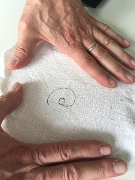
Seems a lot of work to draw an “@” symbol in a piece of cloth, but the learning made it all worth it!
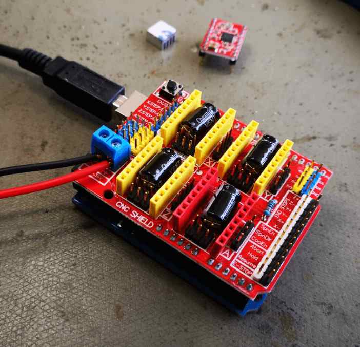
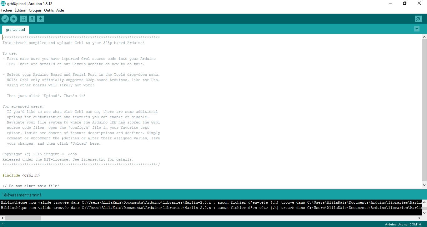
My part is to provide an Arduino Uno with a shield, printer drivers and software that the stepper motors for the work process can be controlled with a G code.
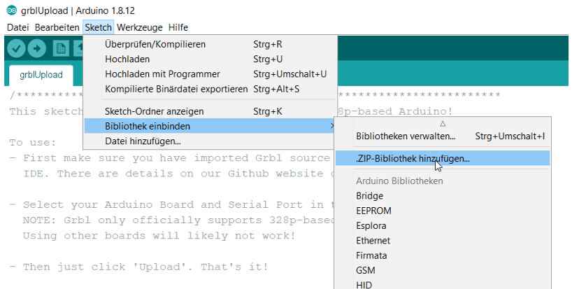
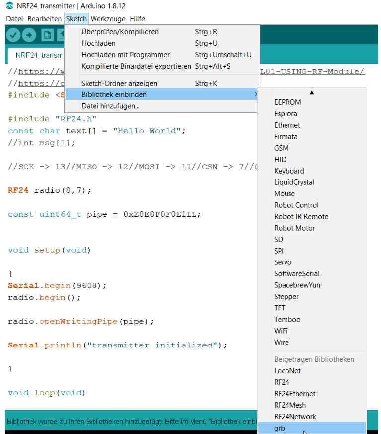
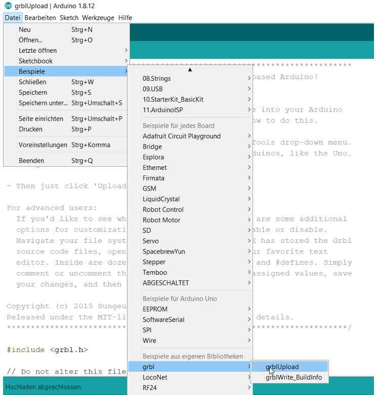
First of all we need the Arduino IDE again and have to load GRBL into the library. Then I put the shield on the Arduino and uploaded GBRL to the Arduino uno.
Check the motors
The next step is to check and prepare the motors so far that they can be connected to the motor drivers on the shield.
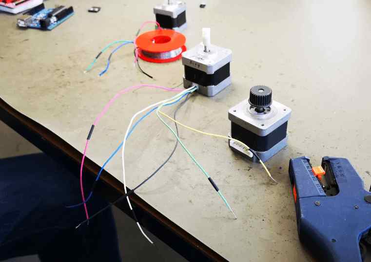
A simple trick to check which pair of cables belongs together is to connect the cables one after the other and to check on the axis whether the resistance increases. If the resistance increases noticeably, the right pair of cables has been found.
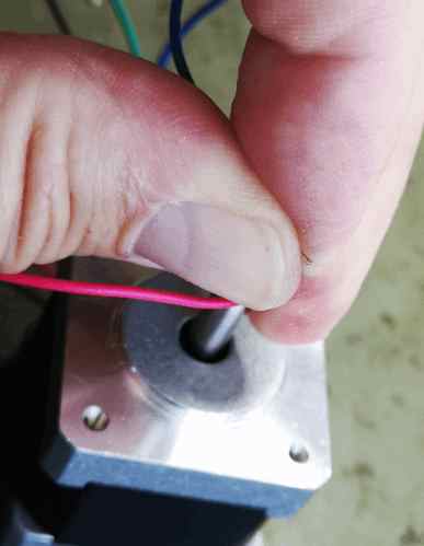
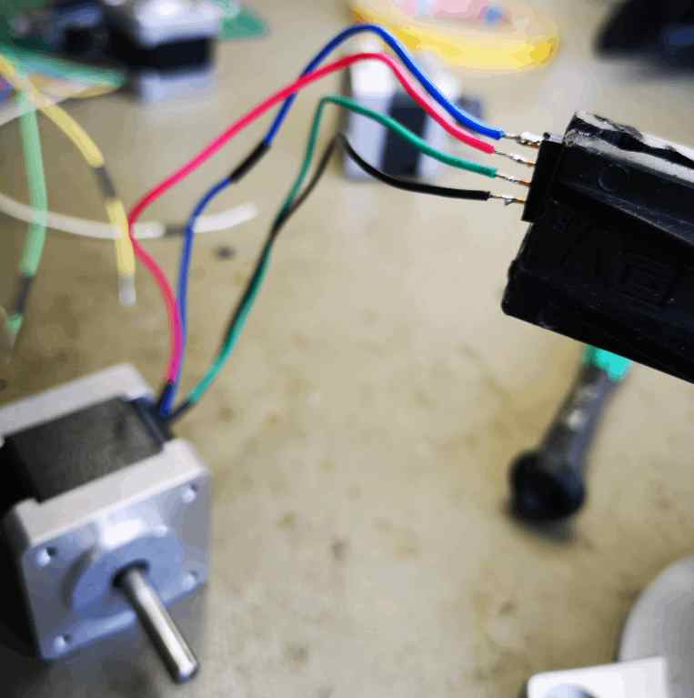
Now the corresponding pairs must be soldered to the plugs.
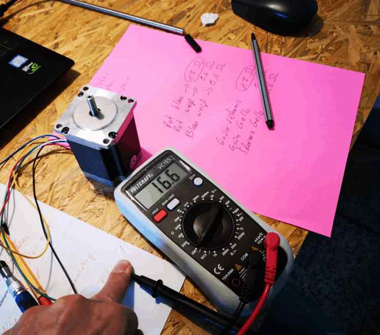
Another way to find the corresponding cable pairs, especially if there are more than four cables, is to measure the resistance. The cable pairs with the greatest resistance belong together.
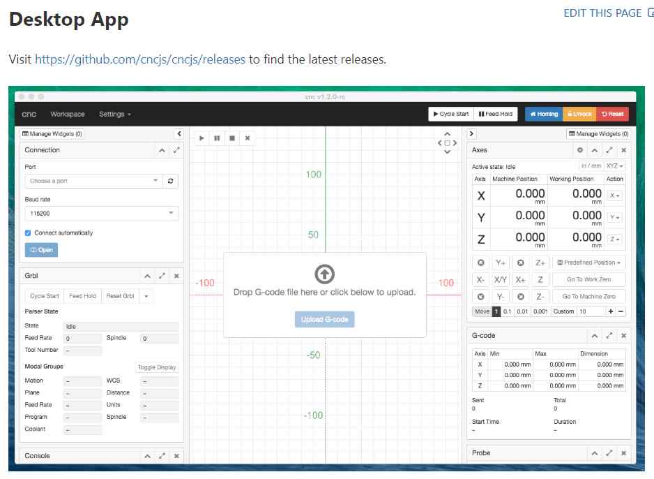
Interface and programm for the gcode
In order to check whether the GRBL is working, we need an interface for CNC milling. Here we chose CNCjs.
Testing the motors, arduino, shield and CNCjs 1.9.22
Since we want to use a stronger motor to lift the sewing facial expressions, we decided on a more powerful printer driver for the Z-axis.
Here we chose the satstep6600 from Daniele Ingrassia.
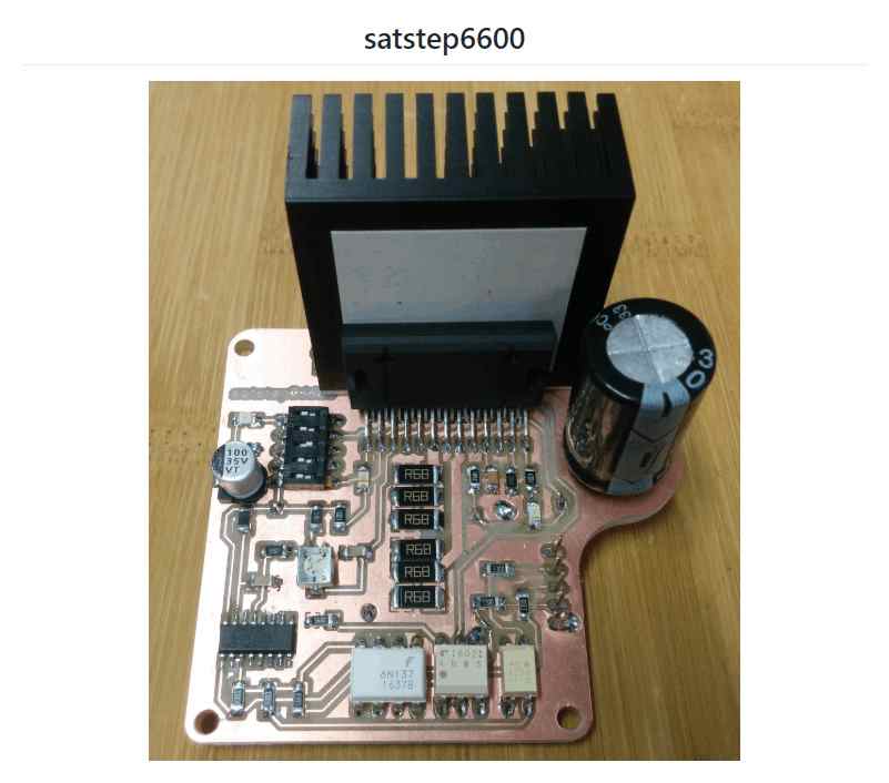
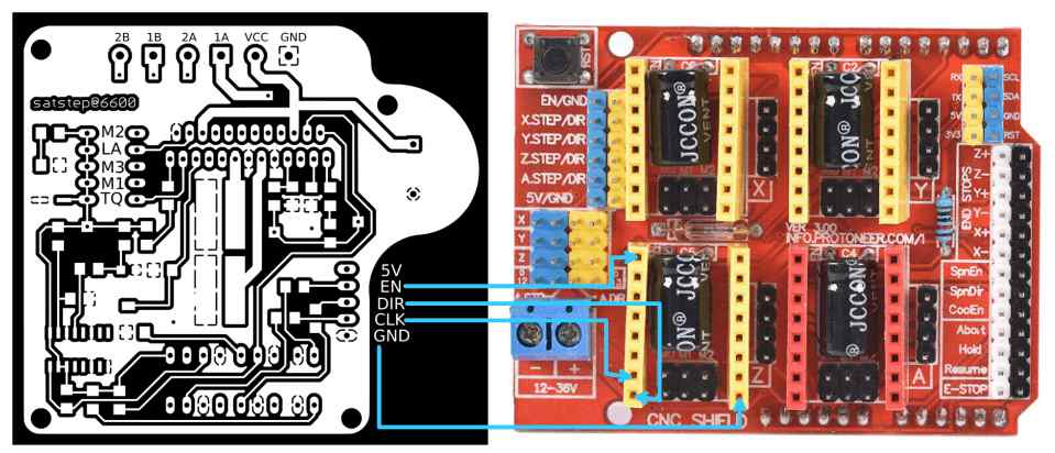
First setting with satstep6600 and a bigger motor
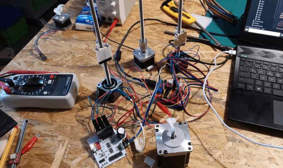
Check the new motor driver and the motors
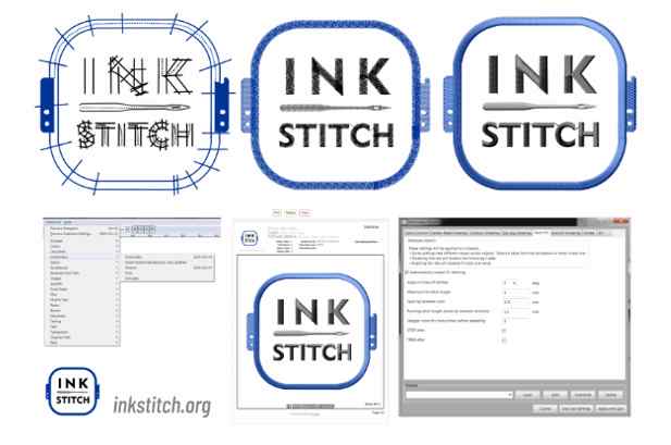
INK STITCH
For Inkscape you can download a plugin called INK STITCH so that we can also send embroidery files as gcode to the machine.
For the german version.
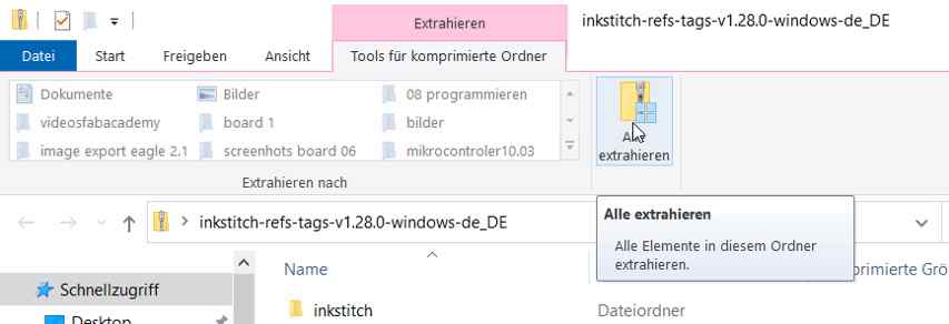
Unzip the ZIP file in the folder.
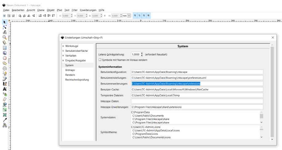
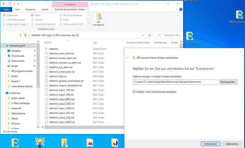
To do this, paste the target directory copied above.
Restart Inkscape
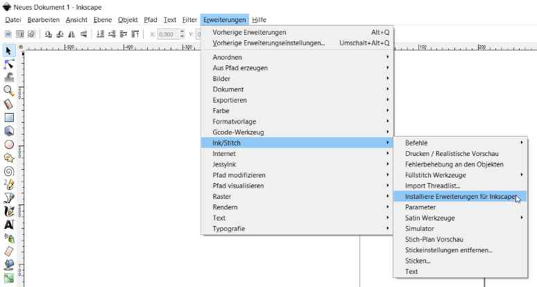
Inscape is installed and it is possible to load directly extensions.
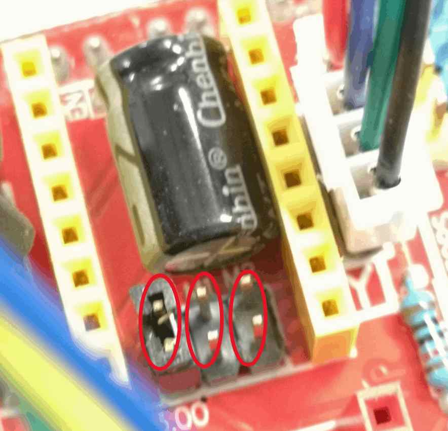


First settings of the electronics at the machine

Top view

Calibrate the axis/motors


Change the settings


Fit and rework the 3d printed parts for the electronics


Calibrate motordriveres with the potentiometer

First assembly test x and y axis

z axis
First settings

Shorten the chain

Testing the movements with a paper handkerchief

No test

Motiv and gcode

How to make the gcode
Useful links
The final Fusion 360 archive is here.
Mechanical and Machine Design @ ENIT
Students:
Marwa BaaloucheKais Alila
Marwa Baalouche
We decided to build a CNCplotter machine.It was Kais's idea.We started to see the different types and structures of plotter machine to finally choose and have a general idea about the components and parts to design. Our design was initially inspired from this model with a xy core.
Machine Design
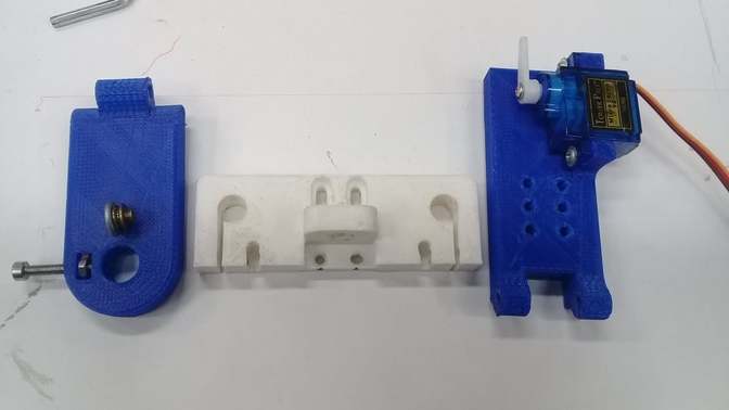
At the design level, I was responsible for the design of the penholder mechanism. It will be composed of two parts, one that will contain the servo motor responsible for the movement of the pen and a lower part on which the pen will be fixed.
so first I started with the first part, I took at the beginning the dimensions of the servo motor then I made the scketch and then I extruded it.
.png)
.png)
Then I added some fixing holes and some guiding part so that the handler will be fixed correctly on the rest of the machine.
.png)
For the second part where the pen has to be fixed, I started with the general shape then I put a place for a screw and a nut to fix it.
.png)
.png)
And here's the final result, I think it's the simplest pen holder but it's also very practical since it allows the pen to be fixed and also its movement by means of a servomotor.
.png)
you can find here thefusion file of this piece
3D Printing
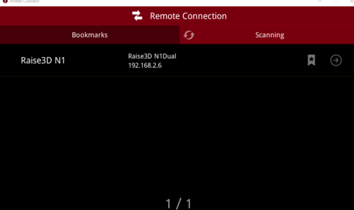
for 3D printing, I was in charge of printing my pieces. So I used our Raise3D N1 for that.
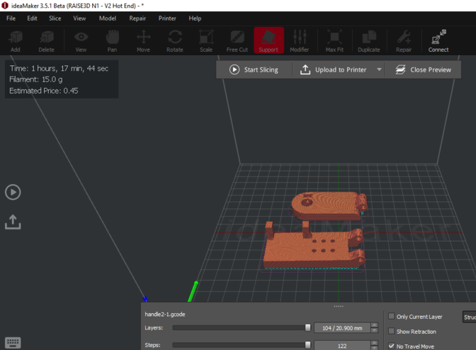
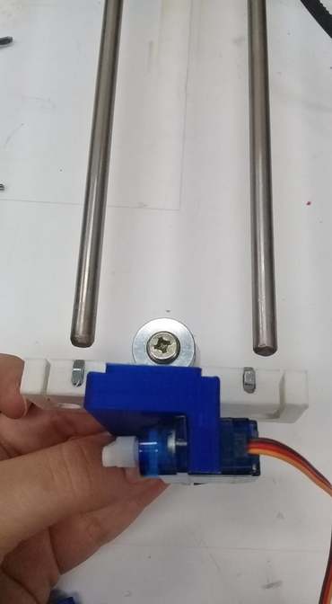
During the fixing of the engine it seems that my part was perfectly adequate with it.
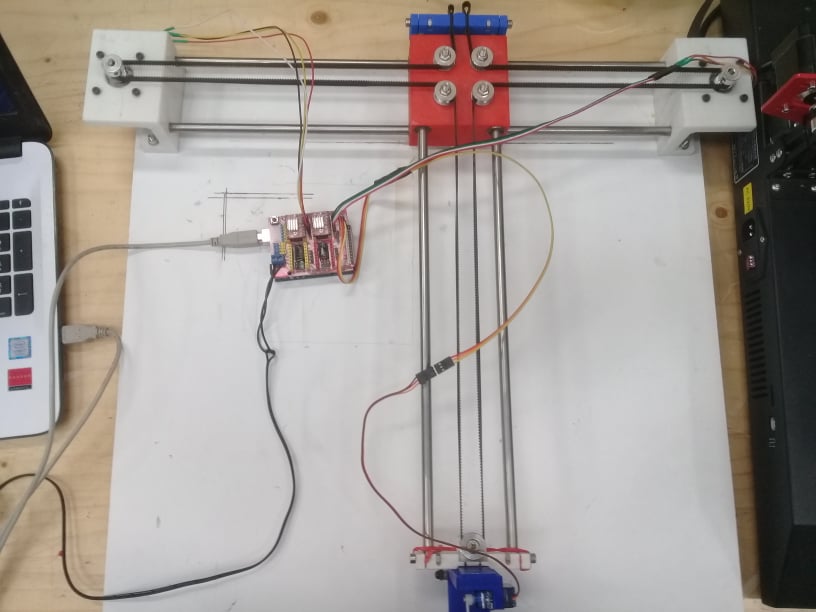
Machine assembly
For the assembly, I was in charge of assembling the pen holder, to fix the motors on the axis which was already assembled by kais and to finish the assembly of the machine.

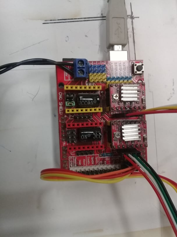
Electronic assembly
So for our machine we need an arduino Uno and a cnc shield , 2 motors and 2 A4998 drivers and a servo motor.the following figure will show the circuit to be made. Of course the CNC shield will be mounted on the Arduino.
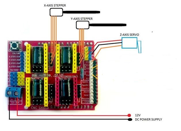
The next step of my work was to check and prepare the motors so far that they can be connected to the motor drivers on the shield. A simple trick to check which pair of cables belongs together is to connect the cables one after the other and to check on the axis whether the resistance increases. If the resistance increases noticeably, the right pair of cables has been found. I also lengthened the servo motor cables and connected all the motors to the cnc shield
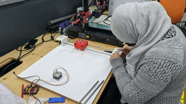
Tests
It was time for me to test the machine after that kais has installed the grbl and tested the machine. For this I used LaserGRBL ( you can download it from here)
Testing the pen holder
Testing the other 2 motors
First plot
Kais Alila
The team decided to build a CNCplotter machine.It was my idea.We started to see the different types and structures of plotter machine to finally choose and have a general idea about the components and parts to design. Our design was initially inspired from this model with a xy core.
Machine Design
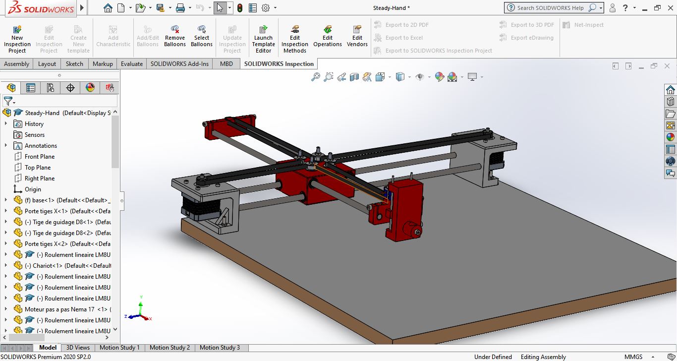
At the design level, I was responsible for the design of the CoreXY mechanism which based on Axidraw machine
The mechanism is as shown here
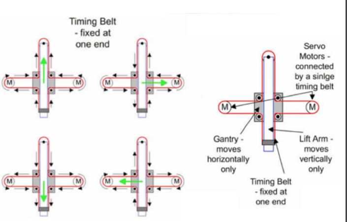
If the steppers turns in the same direction the stepper goes on X axis and if the steppers are not in the same direction the systems goes on Y axis.
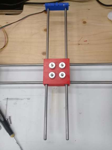
So first i designed the center part which will contain 8 LM8UU lineair bearings and 4 608 Beraingns for the timming belt.
Based on the center part i modeled the two support for steppers and the lineair rods
The other team member designed the other parts and I did the assembly on solidworks before that we start manufacturing. I added the steppers the servo, the bearings and the belt to the design and here how it looks
Manufacturing
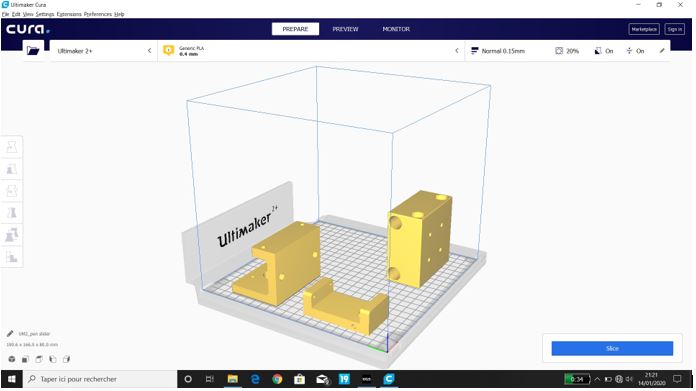
3D Printing
For 3D printing, I was in charge of printing some of the pieces. So I used our Ultimaker 2.
Electronics
So for our machine we need an arduino Uno and a cnc shield , 2 motors and 2 A4998 drivers and a servo motor.the following figure will show the circuit to be made. Of course the CNC shield will be mounted on the Arduino.


Software
Thsi part I was responsible on is to program and configure the arduino.
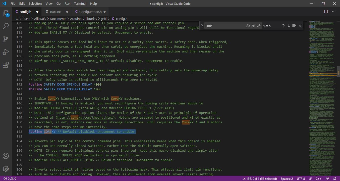
The software we used is GRBL which is a very good open source software to control CNC. For this project We used CoreXY system so the first step I ve done is to change in config.h in grbl folder
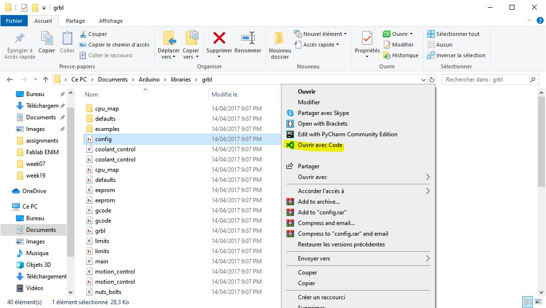
Search for #define COREXY Uncomment #define COREXY // Default disabled. Uncomment to enable.
Upload the code in the arduino
To configure GRBL you need just to follow the steps in the GRBL Wiki it was good documented in github.
We can use The serial monitor to configure GRBL or just connect the board with UGS
-
Send $$
-
Start configuering
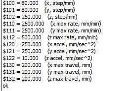
I adjusted the step per mm for X and Y axis $100=80 $101=80 beccause we are using a GT2 belt
and then I adjusted the speed and acceleration as shown in the previous image.
G code generation
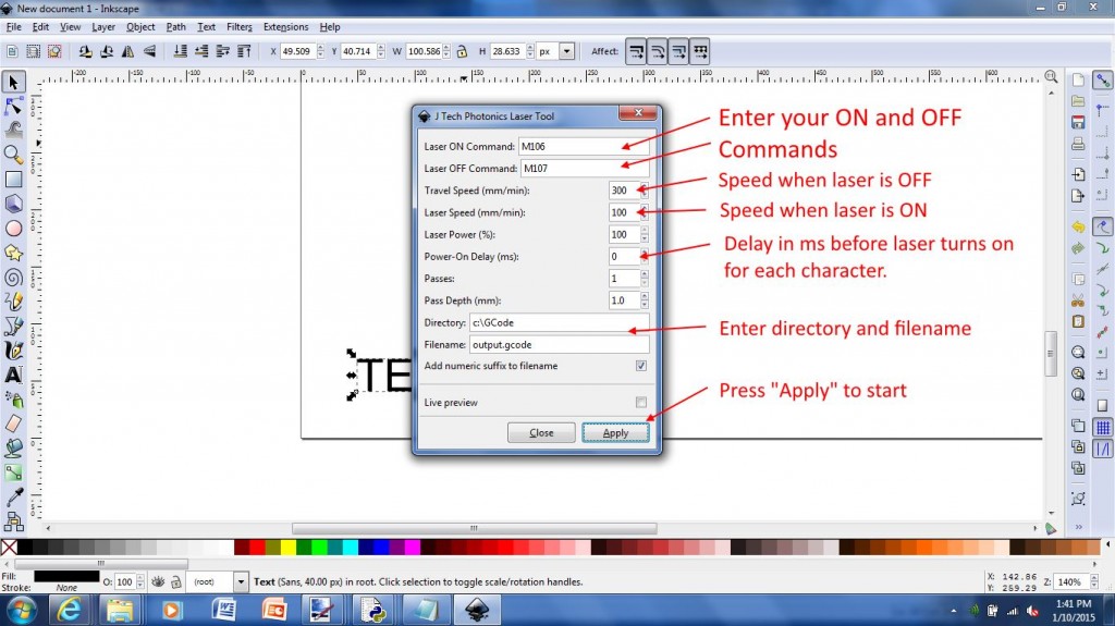
The first test for the machine was generated using inkscape and JTP laser tool plug-in realy usefull and easy interface & the g-code generated is compatible with plotter functions.
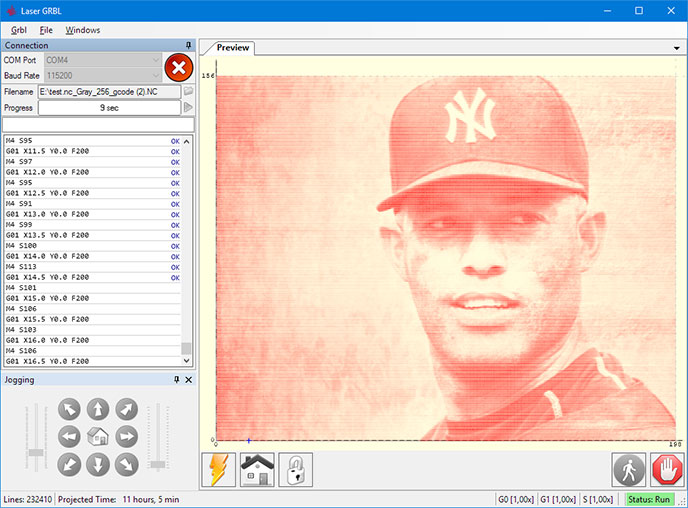
The second software tested was LaserGRBL) which is one of the best Windows GCode streamer for DIY Laser Engraver. LaserGRBL is able to load and stream GCode path to arduino, as well engrave images, pictures and logo with internal conversion tool
Tests
For the tests We used LaserGRBL ( you can downloaded from here)
Testing the other 2 motors
First Plot