5. Electronics production
Process Characterization: PCB production
Group assignment
| Have you? | Done |
|---|---|
| Group assignment: | ⬇ |
| Characterize the design rules for your PCB production process: document feeds, speeds, plunge rate, depth of cut (traces and outline) and tooling. | Yes |
Link to group assignment page
Incite Focus: Characterize the design rules for your PCB production process
Individual assignment
| Have you? | Done |
|---|---|
| document your work (in a group or individually) | Yes |
| Individual assignment: | ⬇ |
| Make an in-circuit programmer by milling and stuffing the PCB, test it, process. | Yes |
| then optionally try other PCB fabrication | Yes |
Checklist
| Have you? | Done |
|---|---|
| Linked to the group assignment page | Yes |
| Documented how you made (mill, stuff, solder) the board | Yes |
| Documented that your board is functional | Yes |
| Explained any problems and how you fixed them | Yes |
| Included a ‘hero shot’ of your board | Yes |
FabTinyISP
In 2020 I made a ARM JTAG programmer and it did not work. I then switched to a FabTinyISP found at Fab ISP Models compilation. This was a much better choice.
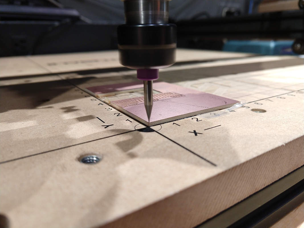
Mill Test Traces

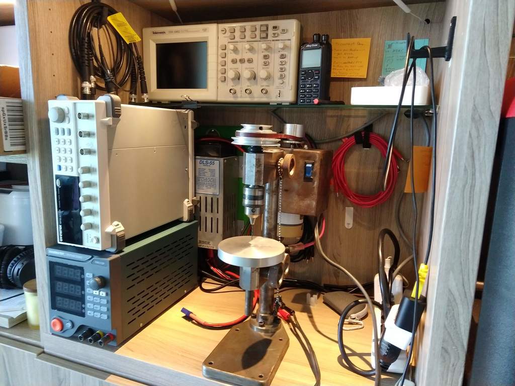
The fab academy test trace file above was use to create cam to test our X-Carve 500mm size milling machine. I purchased the smallest 500mm model of the X-Carve mill because it would be more rigid and so it would fit on a normal work bench top.

I had been told that it was impossible to micro-machine or mill a circuit board on a lower cost (sub $1000) milling machine like an x-carve. I suspected that this was not true, so I proceeded in the following way. It seemed to me the mass of the spindle, small cutting diameter, and rigidity of the machine was capable. I did know that vibration and concentricity of the tooling in the spindle may be important.
I wanted to make sure my x-carve spindle was ready for micro-machining. The first few times I tried to machine my circuit board on my x-carve it broke the 1/64” diameter end mill almost immediately. The bit also seemed to be vibrating a lot despite the fact that the spindle itself was runny vibration free and quietly. Being trained as a machinist years ago, I knew I should check the spindle and tooling run-out of the 400watt 48vdc quiet cut spindle we have installed on our x-carve mill. Below you can see photos where I am using a Mitutoyo 513-406-10E Dial Test Indicator to check the runout. This specific Dial Test Indicator was suggested by Ron Reed at Precise Bits a micro machining supplier I called in the process of researching micro-machining.


After rotating the tooling, collet and spindle the Total Indicated Run-out (TIR) measures a max of .0015” which is OK for a 1/64” diameter bit, but could be improved. I am waiting for some new collets from Precise Bits and we will see if they can improve TIR.

The above test trace file was cut with the following parameters:
| Feed Rate | Speed | Plunge Rate | Cut Depth | Tool | TIR |
|---|---|---|---|---|---|
| 254 mm/min (10 ipm) | 12,000rpm | 25mm/min (4 in/min) | 0.10mm (.004 in) | 0.4mm (1/64”) 2FL CU 129974 | 0.4mm (.0015 in) |
The test traces came out quite good for the purposes of the Fab Academy and matched the typical output of a Modela mill. The traces stayed in place into the 4th segment from the left, this means all typical trace widths will be easily machined on our x-carve. If I have time I will further optimize the x-carve with a focus on further reducing TIR.
The section above satisfies the group assignment assessment requirements of:
- Characterize the design rules for your PCB production process: document feeds, speeds, plunge rate, depth of cut (traces and outline) and tooling.
- Document your work individually
Making: FabTinyISP
After being unable to program a ARM based JTAG programmer I made, I checked in with the Saturday Zoom help group. Pablo and Adrián from Fab Lab Leon both suggested that I make a FabTinyISP first and then move on to other boards. I took their advice and followed these instructions to make a FabTinyISP
I will return to my ARM JTAG Programmer project at a later date and my work and documentation will be updated here: JTAG Programmer
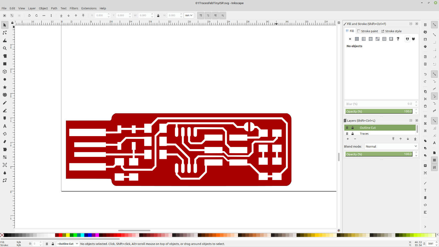
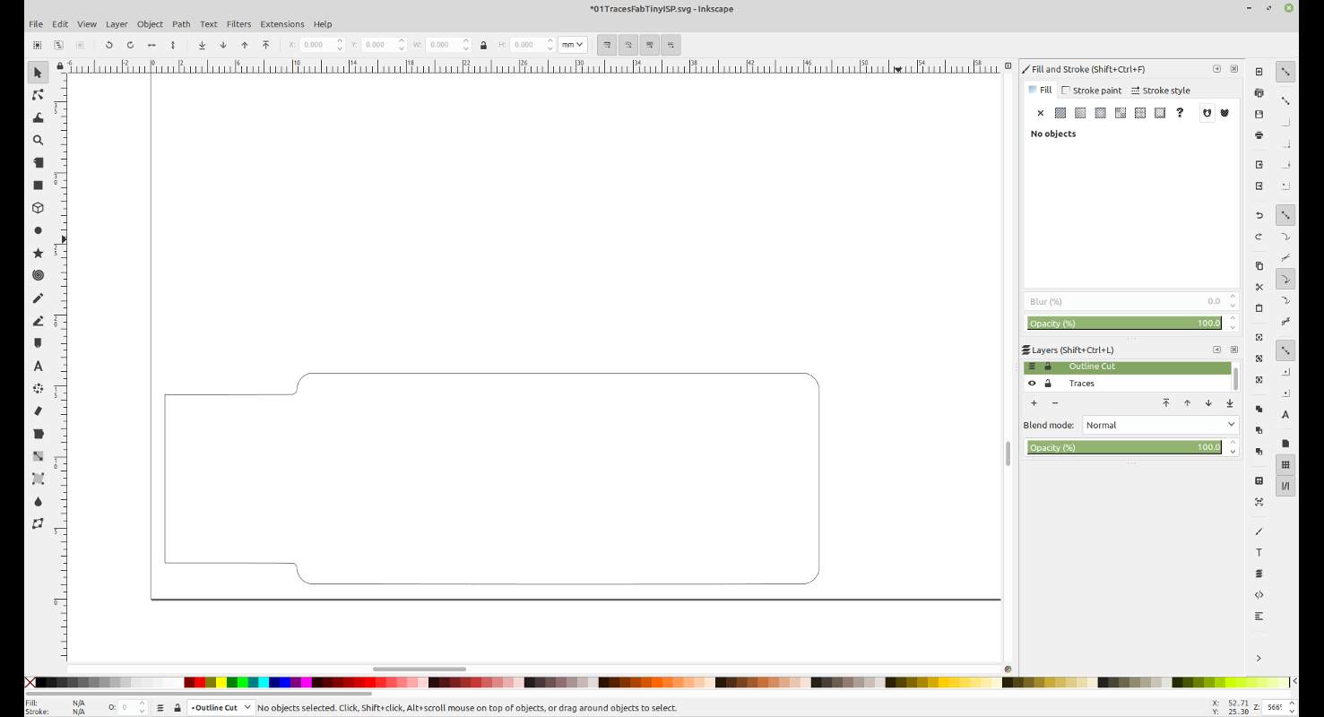
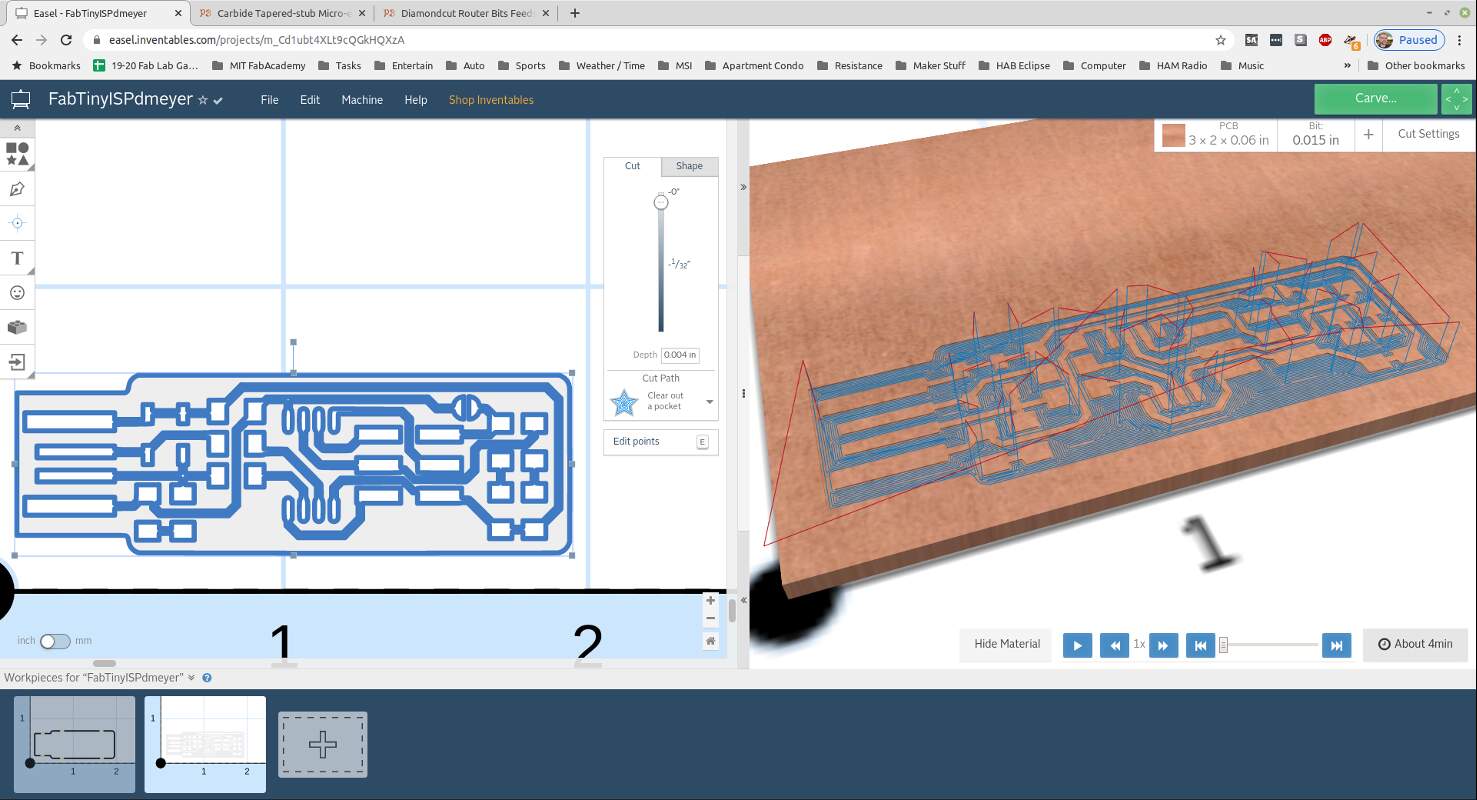
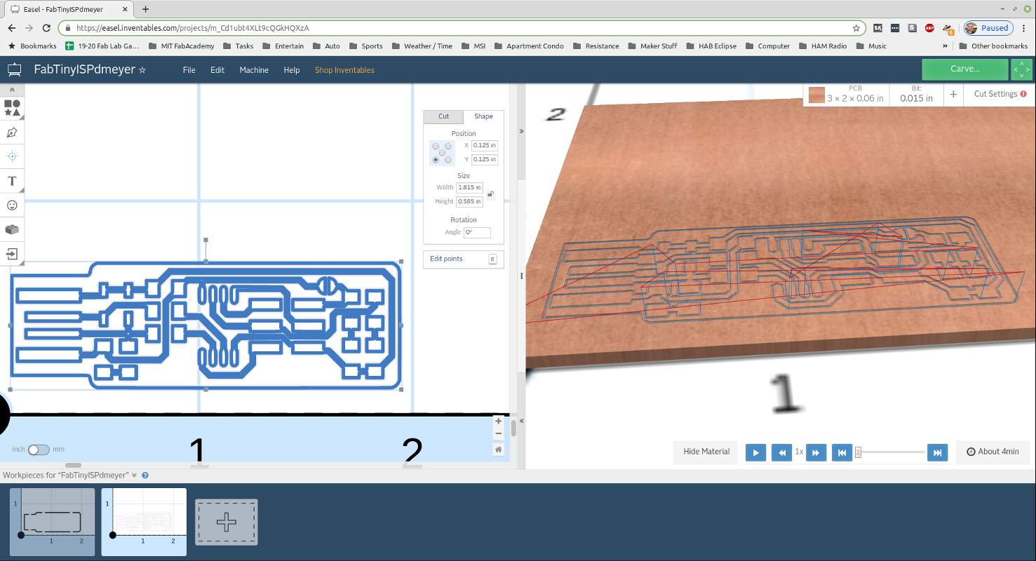
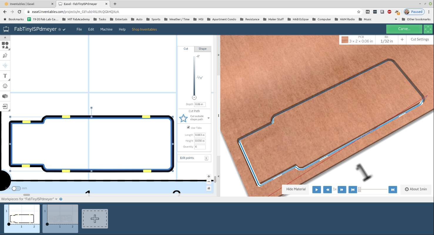
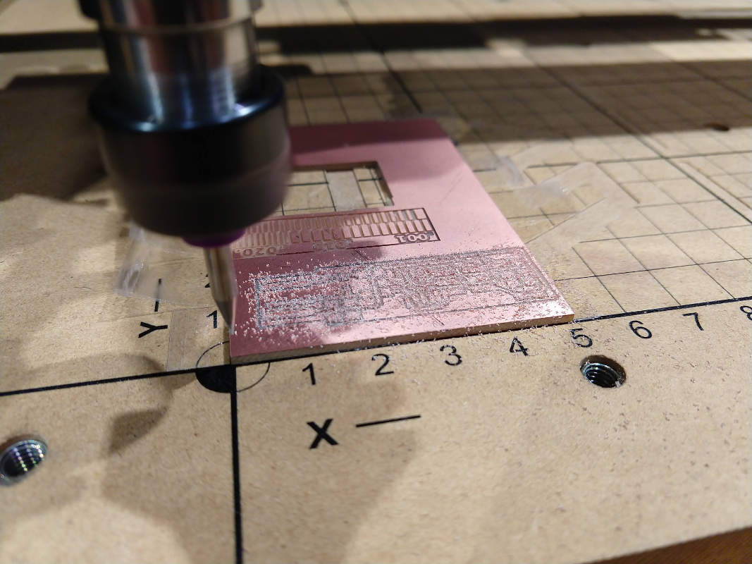
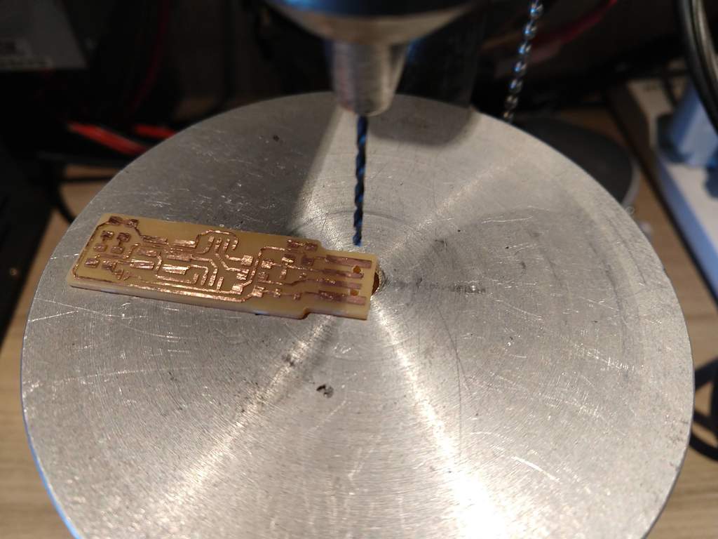
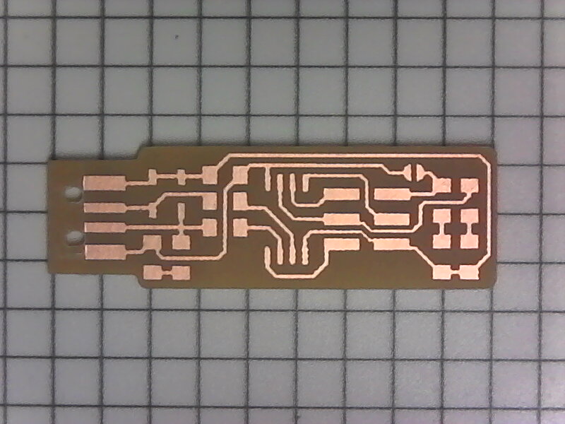
Milling
I used the same steps to mill the board as documented for my JTAG Programmer.
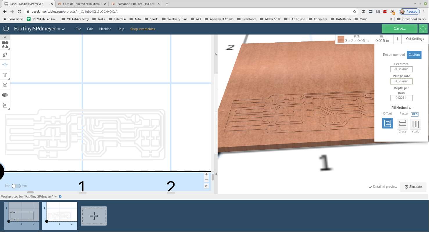

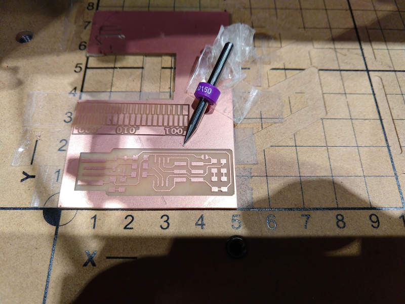
Establishing Feed Rate
Calculations for a PreciseBits EM3E8-0150-15V Tapered Stub End Mill were completed using:
PreciseBits Taper Stub End Mills under the Feeds / Speeds Tab
For a 0.0150” (0.38mm) dia - multiply your peak spindle RPM by 0.00381 (dry) or 0.00492 (with ME Lube ) with 20 IPM z-axis plunge rate
Mods suggest 4 mm/s feed, which is 9.5 ips. I’m guessing that this is a recommended starting speed?
The calculated feed rate for my 0.0150” (0.38mm) dia Tapered Stub End Mill is:
Multiply your peak spindle RPM by 0.00381 (dry) or 0.00492 (with ME Lube ) with 20 IPM z-axis plunge rate.
Dry: 12000 * 0.00381 = 46 IPM (19.5 mm/s) Lubed: 12000 * 0.00492 = 60 IPM
I will try dry machining first: 46 IPM (19.5 mm/s)
19.5/4 mm/s= 4.875 IPM
So a feed rate of 46 IPM (19.5 mm/s) is ~4.875 times the feed rate of 4mm/s I was using originally on mods. TIR checks and using the feed calculations to obtain the correct chip load for my 0.0150” (0.38mm) dia 3 flute Tapered Stub End Mill Part Number EM3E8-0150-15V really paid off. Circuit boards will be much faster to make on my x-carve 500x500 mill going forward. The x-carve costs around $1,900 with all the parts needed to get started. The PreciseBits EM3E8-0150-15V mill I used costs $16.15 It is very durable due to its 15deg taper geometry. I think this new setup will be better for beginners and will prevent bit breakage. It is also faster than our previous process.
| Machine | Feed Rate | Speed | Plunge Rate | Cut Depth | Tool | TIR |
|---|---|---|---|---|---|---|
| Modela MDX-20 | 254 mm/min (10 ipm) | 12,000rpm | 25mm/min (4 in/min) | 0.10mm (.004 in) | 0.4mm (1/64”) 2FL CU 129974 | 0.4mm (.0015 in) |
| X-Carve 500x500mm | 1168 mm/min (46 ipm) | 12,000rpm | 508 mm/min (20 in/min) | 0.10mm (.004 in) | PreciseBits Taper Stub End Mill 0.38mm (0.0150”) dia, 2 Flutes | 0.4mm (.0015 in) |
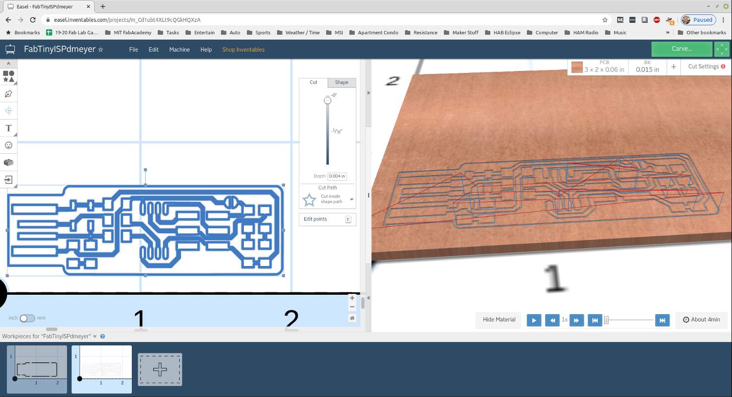
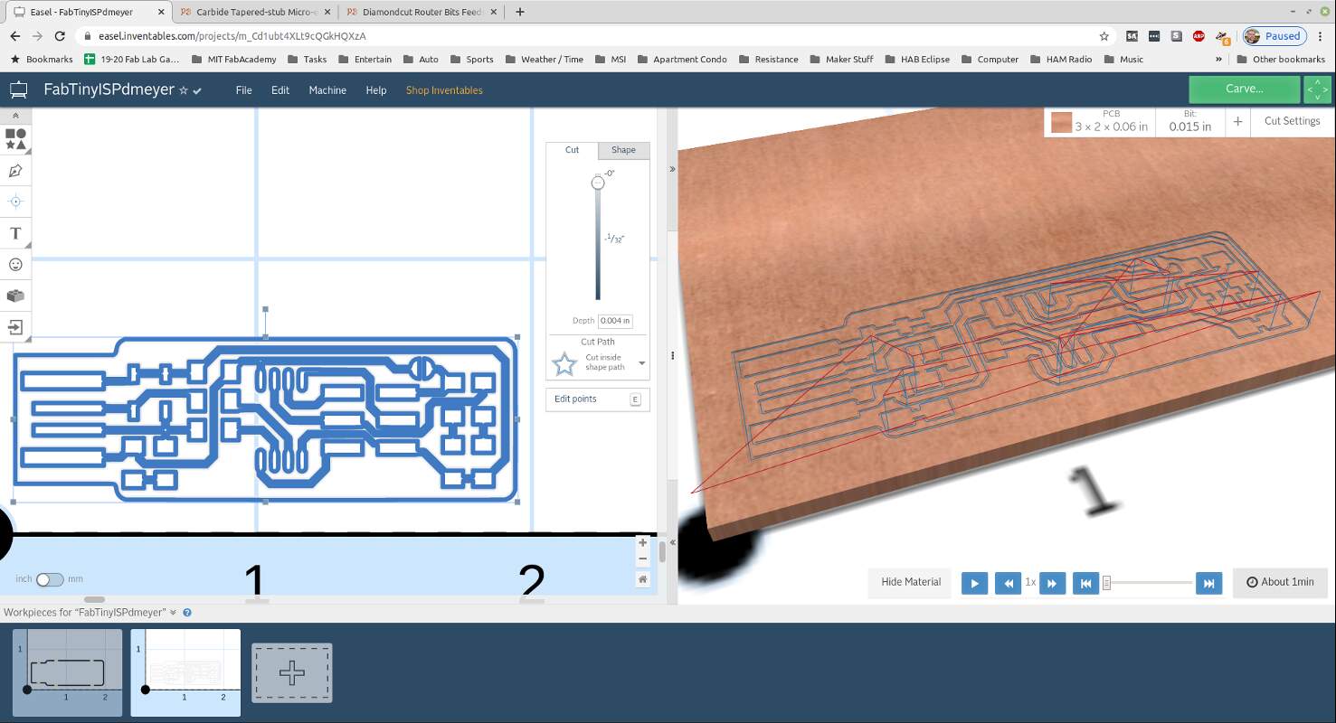
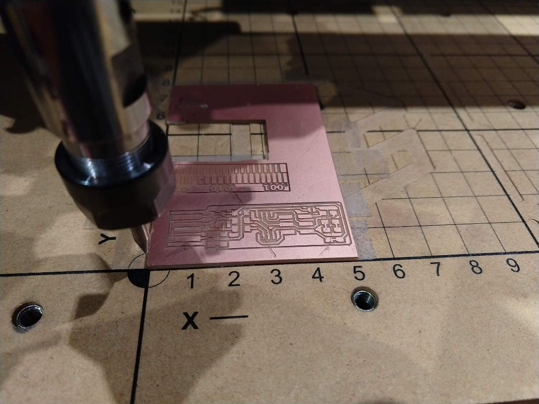
Machining at 46 IPM (19.5 mm/s)

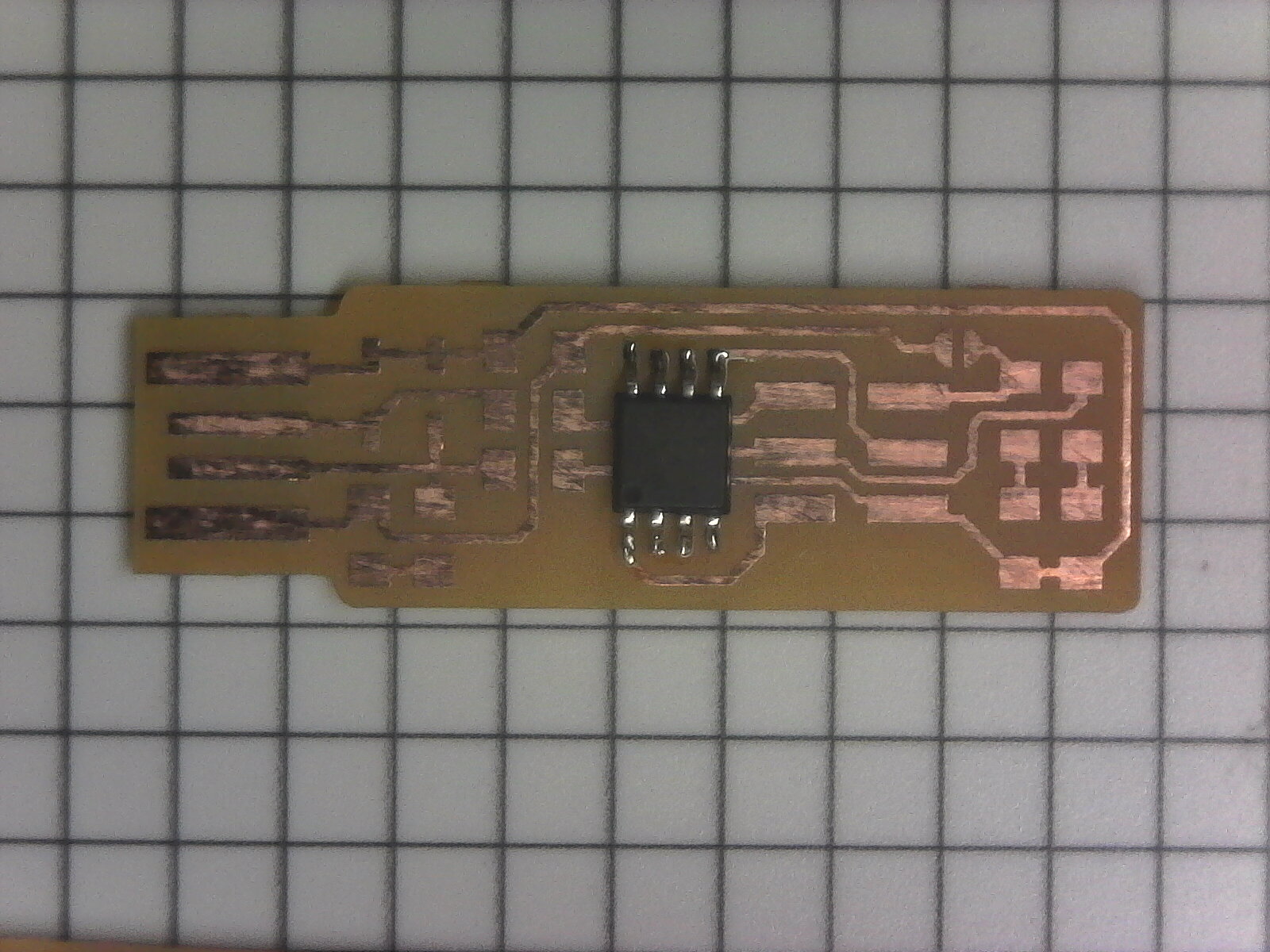
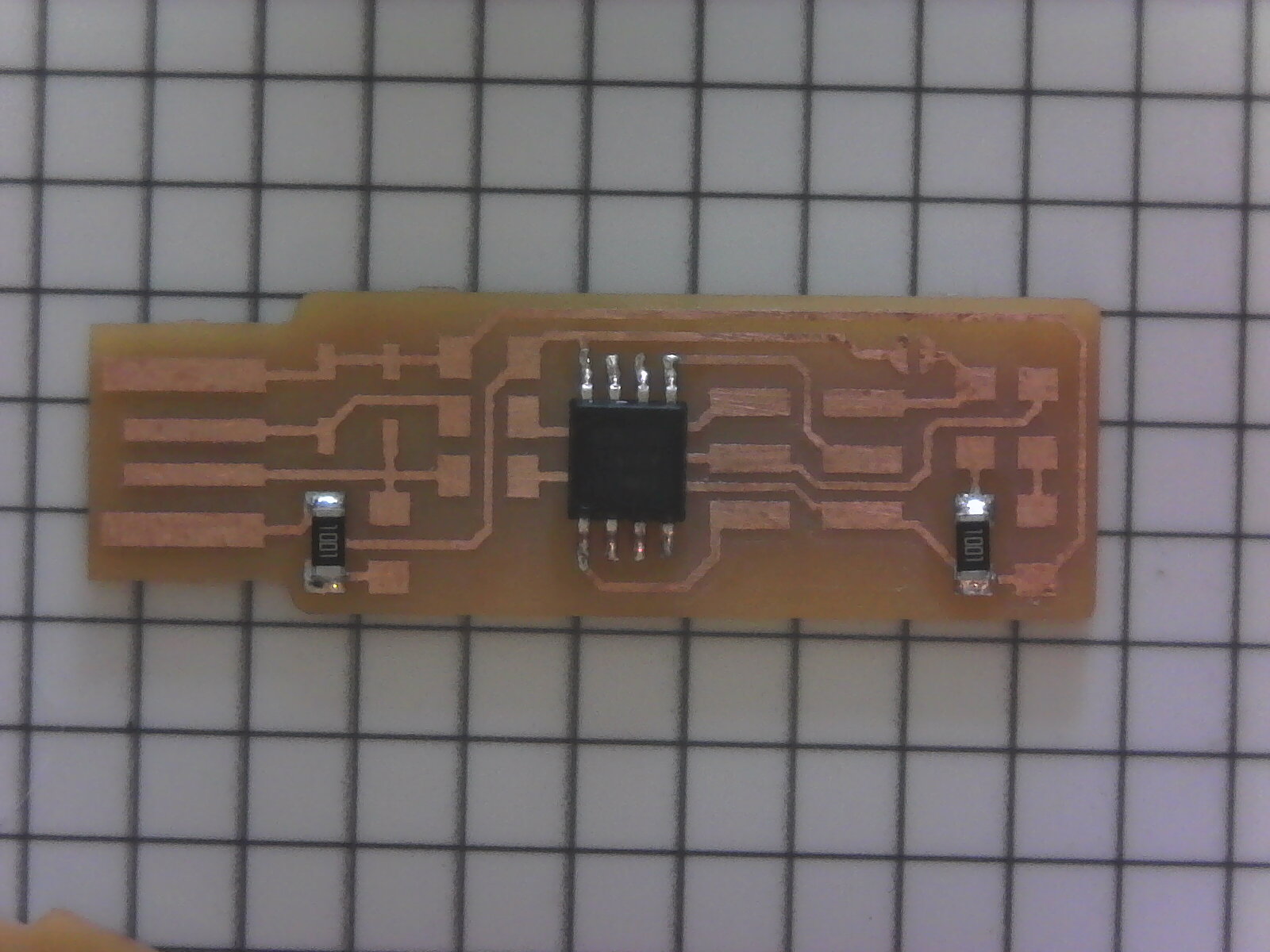
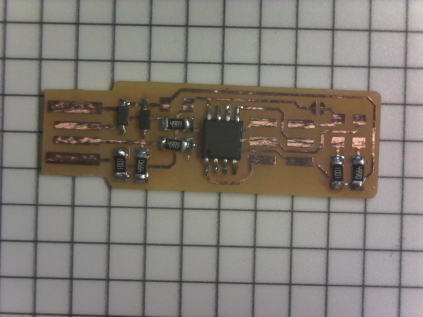
Stuffing
Now time to pick out the parts needed to populate the board!
FabTinyISP BOM:
| Item | Qty |
|---|---|
| ATtiny 45 | 1 |
| 1kΩ resistors | 2 |
| 499Ω resistors | 2 |
| 49Ω resistors | 2 |
| 3.3v zener diodes | 2 |
| red LED | 1 |
| green LED | 1 |
| 100nF capacitor | 1 |
| 2x3 pin header | 1 |
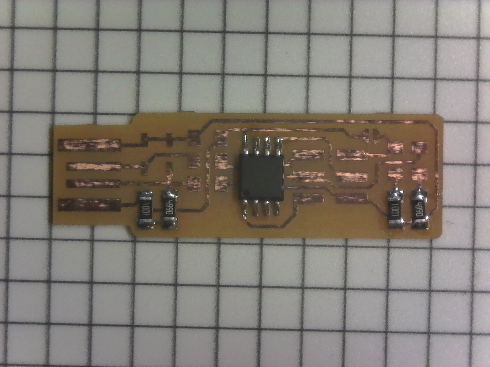
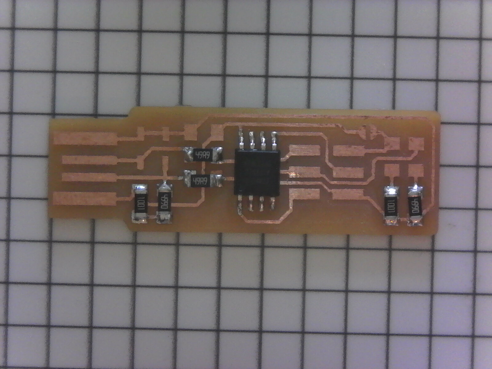
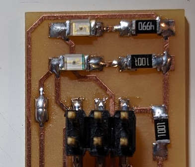
Soldering
I used my plugable USB microscope to document stuffing soldering.
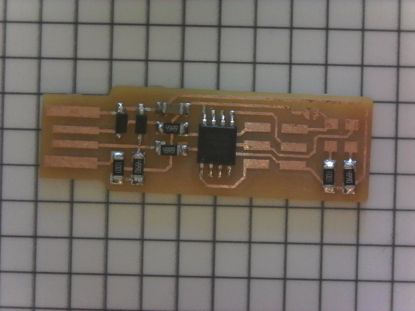
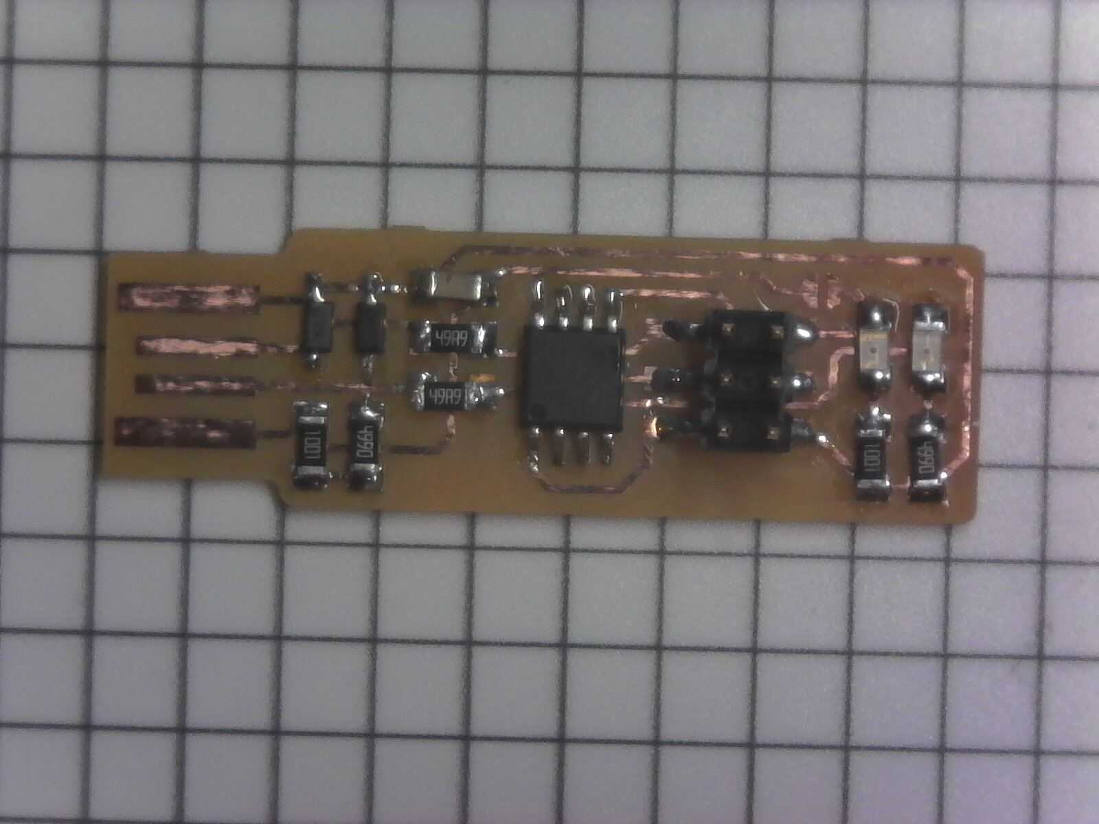
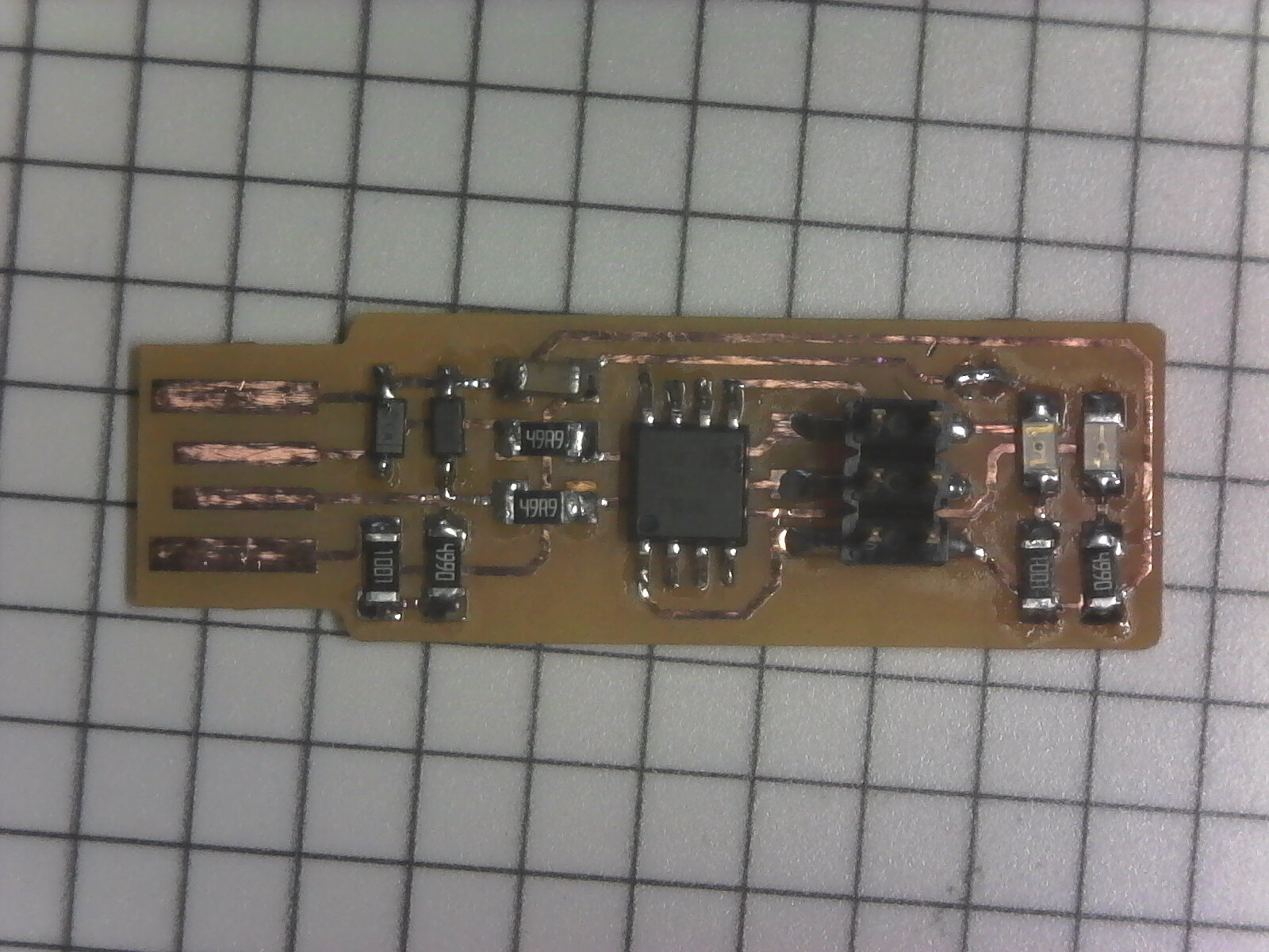

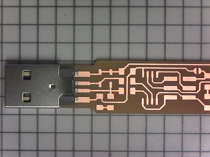
Adding a USB plug
I was having frequent communications issues with the as designed USB interface. I decided to add an off the shelf surface mount USB A Connector. After this my boards no longer had any communication issues.
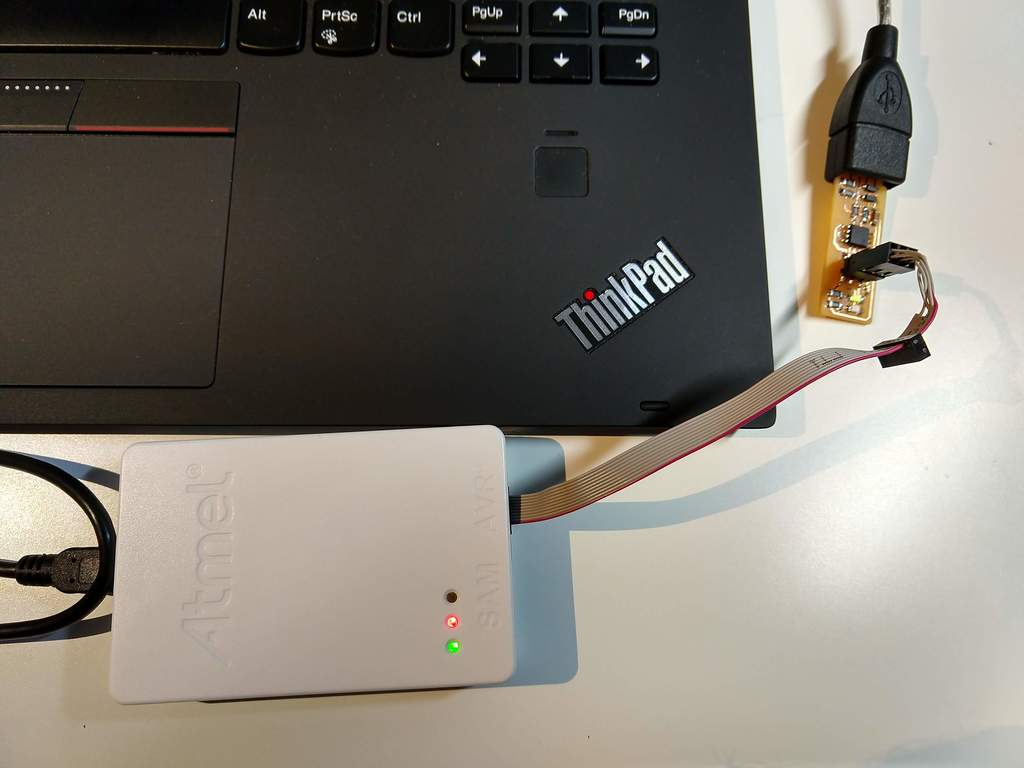
Functioning: Circuit Board
I programmed my first FabtinyISP board the Atmel ICE programmer.
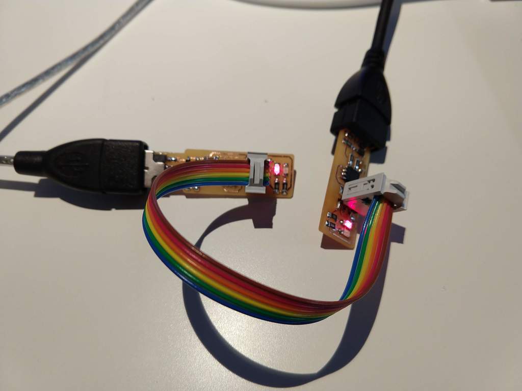
I then used my new FabtinyISP to program my other three FabtinyISP boards I had milled and stuffed.
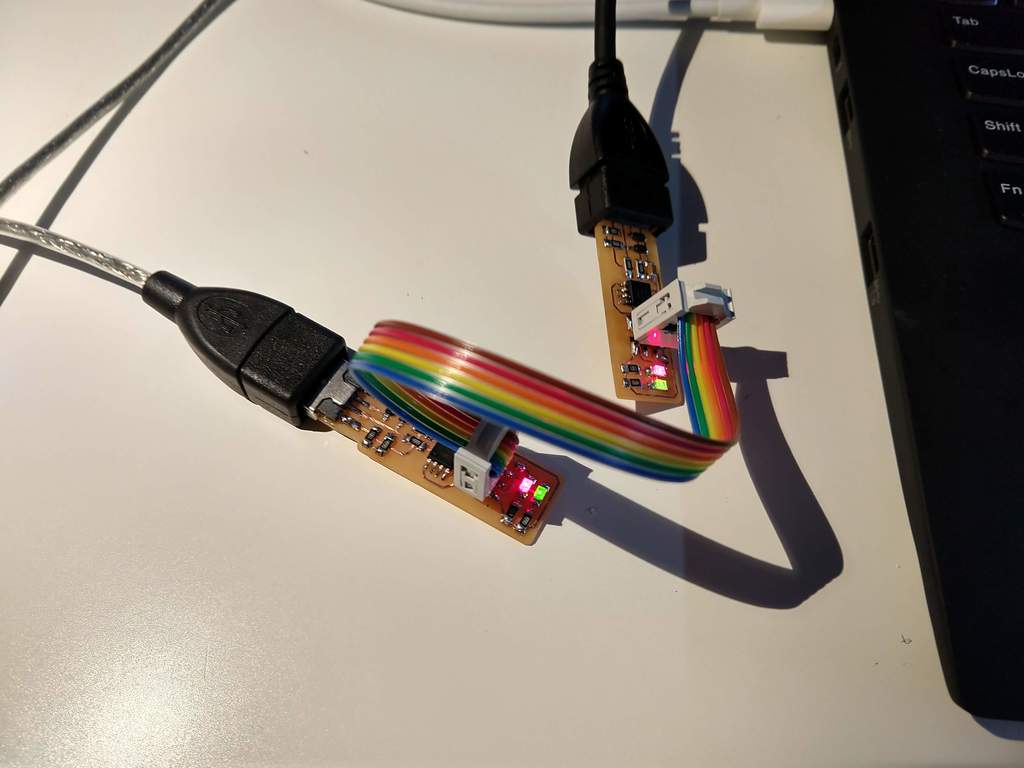

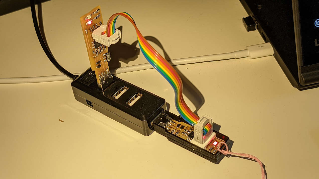
Three of my FabtinyISP boards worked, on did not, i put that board aside for trouble shooting later. On two of my boards I mixed up the 499Ω and 49Ω resistors. This prevented programming of the fuses, but seemed to not impact flashing. After removing and replacing the resistors I re-flashed all the boards and everything worked. I used the steps at FabTinyISP Site to program, set fuses and test my boards. The steps taken were:
- Use a USB 2.0 Mini Hub with Power Switch from Adafruit
- Linux Command: make flash
- Linux Command: make fuses (Don’t forget this step!)
- Unplug both programmer and my board
- Plug in my board
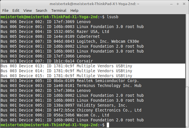
- Linux Command: lsusb outputs Multiple Vendor USBTiny
- Plug in both programmer and my board
- Linux Command: make rstdisbl
- Remove solder bridge
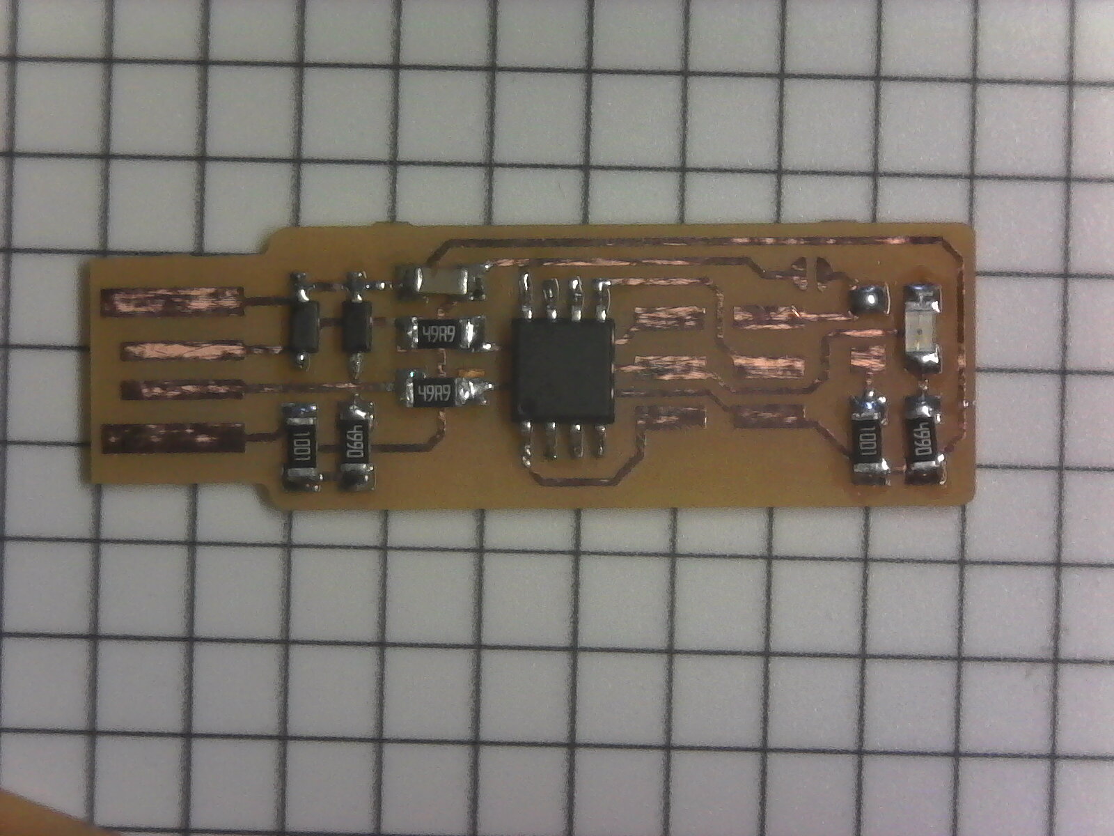
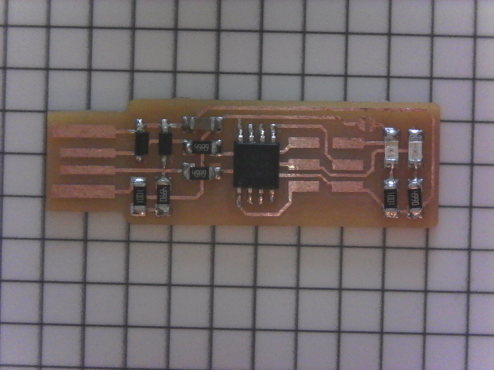
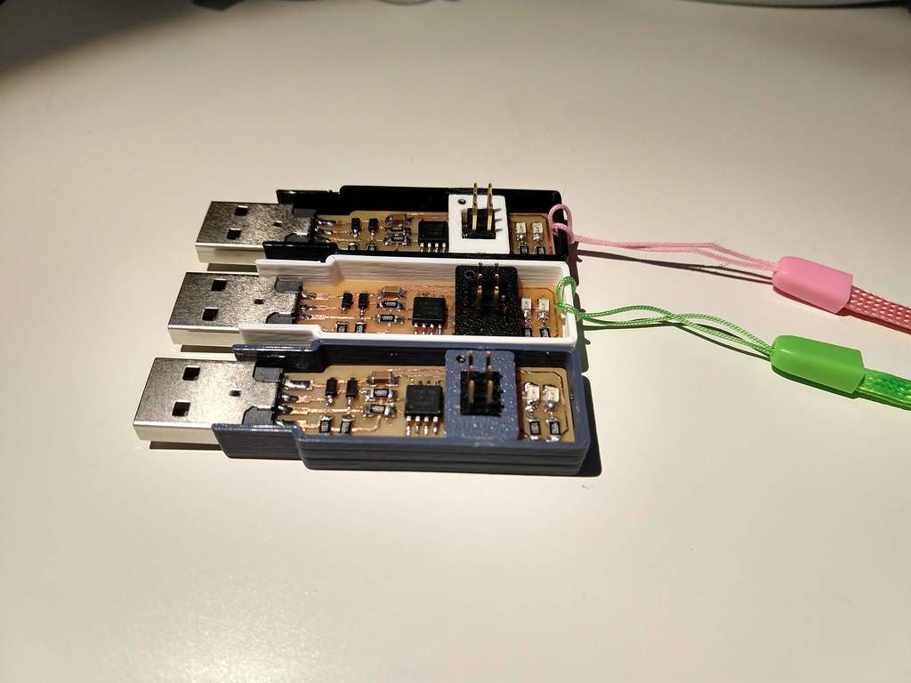
Hero Shot: Working Board
Here is a photo of my working boards:
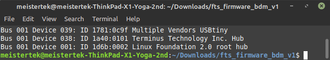
Here is the output of the lsusb command, you can see all three of my working FabTinyISP boards listed and highlighted in white:
Photos of Programming steps
J1 Soldered Shut
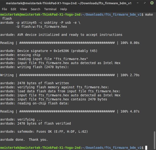
make flash command results
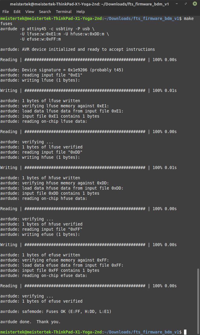
make fuses command results
lsusb with new board plugged in!
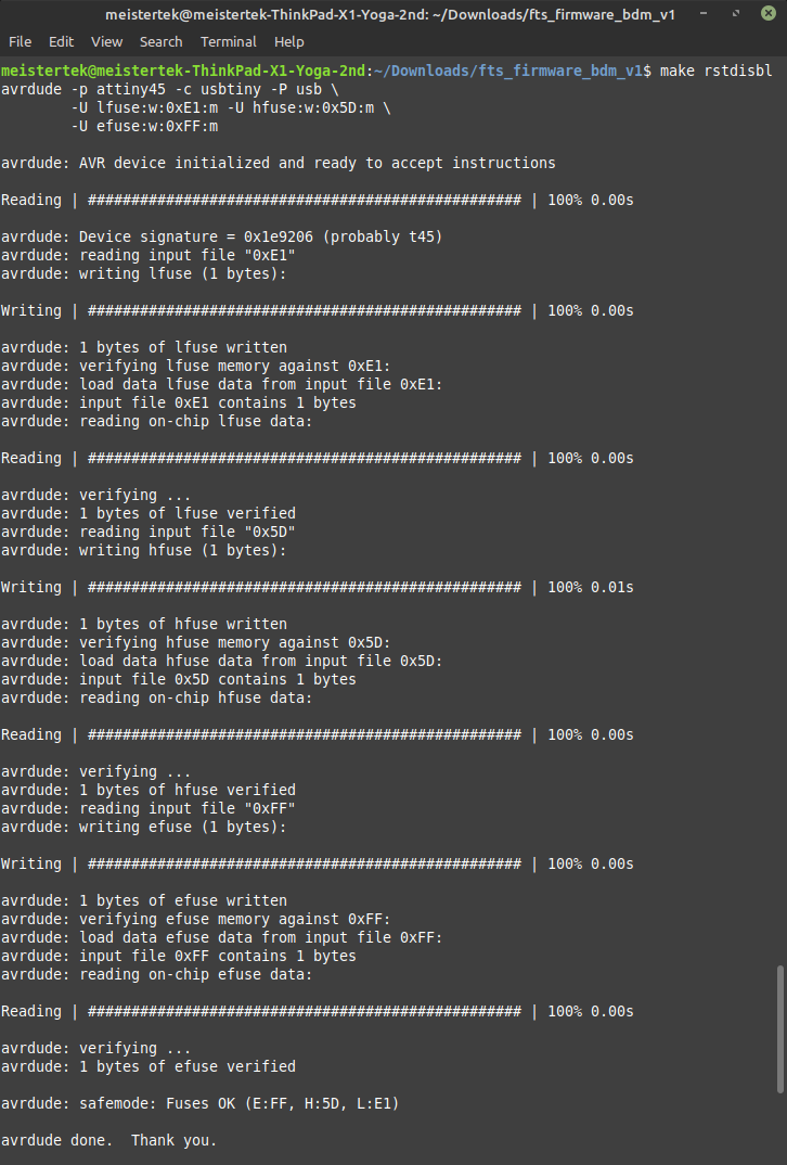
make rstdisbl command results
Week 05 board programs Week 07 board!
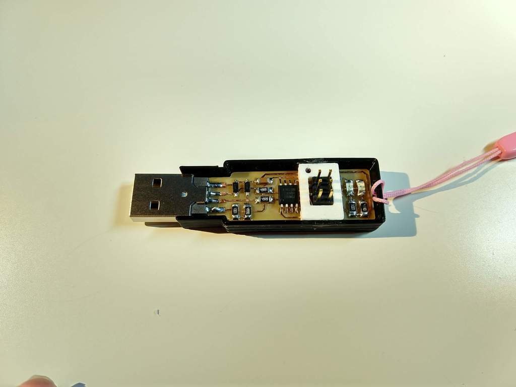
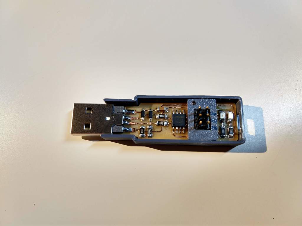
Case for FabTinyISP
I designed and 3D printed case for my new FabTinyISP’s. I hot glued my boards into the case. Then I hot glued a header reinforcement frame around the isp header. I marked the frame with a black dot indicating pin one.
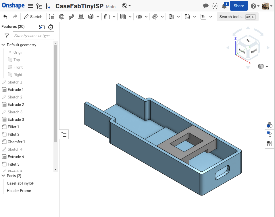
Onshape CAD for Case
Assessment self check
| Have you? | Done |
|---|---|
| Group assignment | Yes |
| Individual Assignment | Yes |
| Documented how you made the board | Yes |
| _Mill | Yes |
| _Stuff | Yes |
| _Solder | Yes |
| Functional Board | Yes |
| Problems fixed documented | Yes |
| Hero Shot | Yes |
Optional Work
Vinyl Cut Circuits
I tried on optional PCB fabrication process. See here for my work on vinyl cut circuits with rounded traces on Garolite sheets.