JTAG Programmer
I decided to make the JTAG (ARM) Free-DAP hello.CMSIS-DAP.10.D11C in circuit programmer (called “JTAG Programmer” from here forward)
Milling
I used the hello.CMSIS-DAP.10.D11C png files to create SVG files to make my JTAG Programmer. I then imported those SVG files into the CAM cloud software Easel by Inventables. Easel is the stock CAM software used for generating g-code to mill stuff on the X-Carve mill. Easel’s by line is “3D Carving Made Easy”, and it’s no bologna, it is pretty easy to use. This is only my 4th milling project using Easel.

Above: tool paths generated by Easel from the SVG CAD file for my JTAG Programmer.

Above: I double stick taped my a 2 x 3 inch FR1 circuit board blank directly onto the x-carve HDF bed.
 Above: The JTAG Programmer being machined. Note mess up to the left, for that cam tool path I used the wrong path setting in Easel.
Stuffing
Now time to pick out the parts needed to populate the board!
JTAG Programmer BOM:
| Item | Qty | Supplier | Part Number |
|---|---|---|---|
| CONN HEADER SMD 10POS 1.27MM | 2 | Digikey | 609-6529-ND |
| CAP CER 1UF 50V X7R 1206 | 1 | Digikey | 445-1423-1-ND |
| IC MCU 32BIT 16KB FLASH 14SOIC | 1 | Digikey | ATSAMD11C14A-SSUTCT-ND |
| IC REG LINEAR 3.3V 100MA SOT23-3 | 1 | Digikey | LM3480IM3-3.3/NOPBCT-ND |
| RES SMD 0 OHM JUMPER 1/4W 1206 | 1 | Digikey | LM3480IM3-3.3/NOPBCT-ND |
Soldering
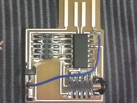
I used our plugable USB microscope to document soldering the JTAG Programmer. I realized while soldering that I had mistakenly milled off one of the traces, so I soldered in a blue jumper wire to replace the trace. I also forgot to get a 0 ohm resistor, so I made a little black jumper wire to go in its place.

Here is a macro video of the soldering process:
Functioning: Circuit Board
I programmed the board with little jumper cable and the Atmel ICE programmer. Programmers programming programmers! For working boards Show 4 step photos or video of the one board working
Hero Shot: Working Board
A single Photo and video of me and my working board will go here when it’s complete! Working on soldering the board as of Feb 27, 2020.
CAD Files
ARM JTAG Prgmr USB Vinyl Optimized: Inkscape SVG file
ARM JTAG Prgmr USB Vinyl Optimized: onshape file I created this CAD file optimized for vinyl cutting just in case the x-carve mill did not work. Also I have a vinyl cutter at home and cannot afford a mill yet. So this file would allow me to vinyl cut my circuit. There are no sharp edges in this design, therefore preventing the vinyl cutter from having to rotate excessively. This allows for finer traces to be cut without them being ripped up.
Tapered Stub End Mills are pretty Awesome!
Machinists Perspective on Micromachining
As a machinist I like to optimize my machine, tooling and process. Optimization allows for more efficient production and room to push limits while maintaining the quality required. In my online research of speeds and feeds I came across a micromachining supplier, Precise Bits, with a large amount of resources on line. I spent some time reading about many of the different end mill geometries that are optimized for electronics trace isolation. I thought maybe a Tapered-stub End-mill would work well, but I wasn’t sure. So I called Precise Bits. Ron at Precise Bits answered the call, and was very helpful. Ron suggested that Tapered-stub End-mills would work well for making circuit boards for Fab Academy. Ron also reminded me of checking spindle, tool holder and end mill for total indicated run-out (TIR). I had used TIR as a machinist, but not for micromachining. Ron taught me about how to do TIR in the context of micromachining. I purchased a Mitutoyo 513-406-10E indicator that Ron suggested. Having a understanding TIR of your spindle, tool holder, and tooling sets a baseline for other variables in micromachining.
Establishing Feed Rate
See my documentation on Tapered Stub End Mills