9. Embedded programming
Individual Assignment
- Read the datasheet for your microcontroller
- Use your programmer to program your board to do something
Group Assignment
- Compare the performance and development workflows for other architectures
- Document your work to the group work page and reflect on your individual page what you learned
- Group Project Link Incite Focus - Embedded programming
Checklist
| Have you? | Done |
|---|---|
| Linked to the group assignment page | Yes |
| Documented what you learned from reading a microcontroller datasheet. | Yes |
| Programmed your board | Yes |
| Described the programming process/es you used | Yes |
| Included your source code | Yes |
| Included a short ‘hero video’ of your board | Yes |
FAQ
- Is it enough for the group assignment if we compare different microcontrollers in theory?
- Answer: No, You need to program at least two different family MCU’s.
- Do I have to design and make a new board for this week
- Answer: No, You can use the board you made in electronics design
- If I adjust existing code, is that now my code?
- Answer: If you use someone’s else code as a starting point, remember that you must acknowledge whoever made it. See General Essentials. To succeed in this assignment, experiment with changing the code, understand how that worked, and write your own.
- How do I prove I’ve read the Datasheet?
- Answer: Point out things in your code and board design that you learned from the Datasheet. Also point to other weeks when you used information from the Datasheet.
- How should I put my code on my website?
- Answer: As a file for download, same as all your other assignments. Keep your web-page tidy and easy to read.
My plan to complete the assignment
Note to self:
KIS keep it simple! Use the board you made in electronics design, the LEDuo to explore performance and development workflows for other architectures. Experiment with changing the code, understand how that worked, and write your own. Point out things in your code and board design that you learned from the Datasheet
2022 plan
- KIS keep it simple!
- Dev spirals must meet checklist and goals of assignment
- Use LEDuo from Electronics Design
- Read Datasheets for:
- ATtiny 3226 by Microchip Technology Inc
- ESP32-WROOM-32x by Espressif
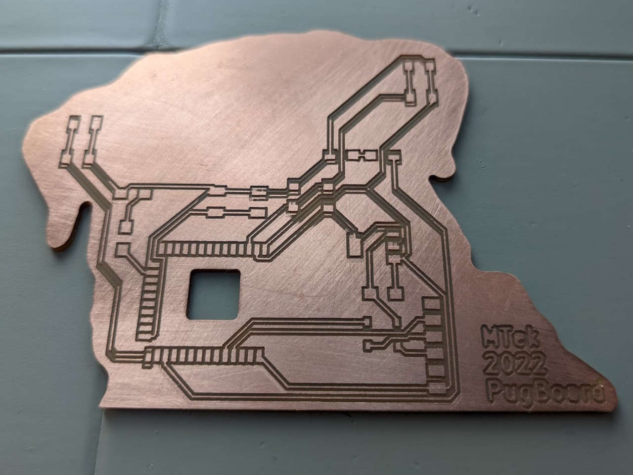
- PugBoard R2: Fab Rev 2 of my PugBoard swapping in an ATtiny 3226
- Explore the development workflows of for the for the microcontrollers above using:
8. Arduino IDE 9. MicroPython
Read DataSheet
ATtiny 3226
Reading the ATtiny 3226 data sheet ,I learned how to decode part numbers. For the part I have in my stock, a ATtiny3226-SU the numbers mean:
AT tiny 3226 - SU -
tiny = AVR Product family 32 KB flash size 2 = 2 series Family number 6 = 20 pins S = SOIC300 package type U = -40°C to +85°C Blank = Standard variant
I like the SOIC300 package it’s compact, but still easy to hand solder. The 3226 ATtiny variant I will be using has the following storage and memory:
| Device | ATtiny3226 |
|---|---|
| Flash Memory | 32 KB |
| SRAM | 3 KB |
| EEPROM | 256B |
| User Row | 32B |
Although the datasheet has a lot of info I find the ATtiny comparison chart on Wikipedia.
It looks the the 2nd generation or 2-series family ATtiny microcontrollers have added the following features over earlier families:
- UPDI programming has been added!
- Two USART compared to one USI or UART or none
- GCC ARch ID avrxmega3 (arch linux?)
- UPDI Program and Debug
I also found out you can sometimes restore bricked AVR chips by using [High-voltage serial]https://en.wikipedia.org/wiki/AVR_microcontrollers#High-voltage_serial to program chips where is reset pin has been disabled by a fuse. This could be useful for brute forcing a program onto a existing AVR in a commercial product for example.
I also learned what a UART is from Wikipedia entry: Universal asynchronous receiver-transmitter
A universal asynchronous receiver-transmitter (UART /ˈjuːɑːrt/) is a computer hardware device for asynchronous serial communication in which the data format and transmission speeds are configurable. It sends data bits one by one, from the least significant to the most significant, framed by start and stop bits so that precise timing is handled by the communication channel. The electric signaling levels are handled by a driver circuit external to the UART. Two common signal levels are RS-232, a 12-volt system, and RS-485, a 5-volt system. Early teletypewriters used current loops.
The ATtiny 3226 has two advanced UART called USART or Universal synchronous and asynchronous receiver-transmitter
I realize now that USART’s were most likely used in my Tandy TRS-80 Modem that I hacked in 1988 as a teenager.
The ATtiny 3226 has 18 GPIO’s and a max frequency of 20MHz. It also has one serial port interface, and two USART/SPI host interfaces, so I am hoping to program my PugBoard with regular FTDI USB to TTL cable. Although it also has a Unified Program and Debug Interface (UPDI) activated by shared pin using high-voltage signal or fuse override. UPDI is really cool, cause it uses only one pin freeing up two pins out of 20 for other functions.
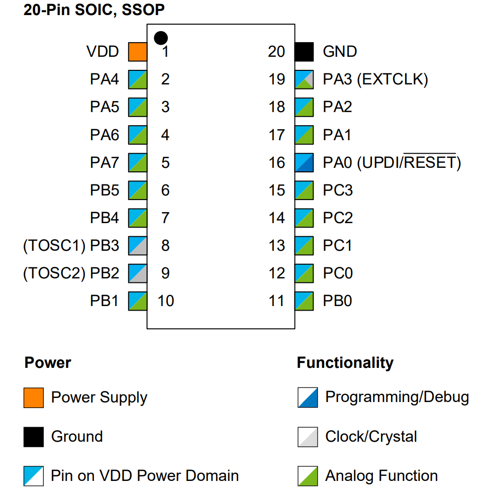
Above: Page 15 of the datasheet has a nice pinout drawing of the 20-Pin SOIC package I’ll be using.
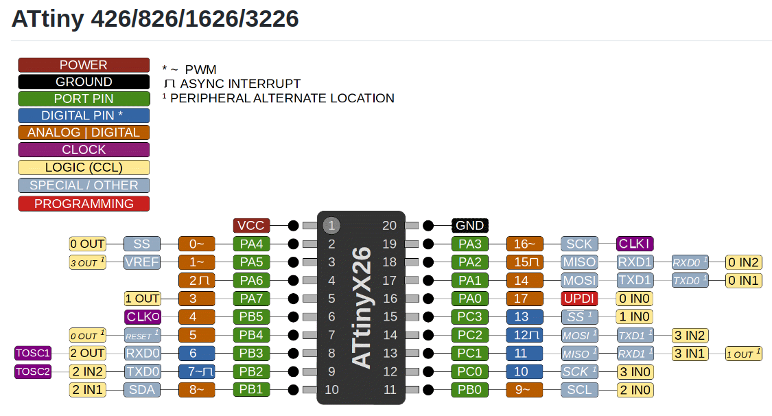
Above: Although this color coded pinout diagram is easier to read. Source
Page 18 has a good chart explaining all the function of each pin that are possible. of note is that USART1 and SPI0 are set as default on pins 17,18, 19. And USART0 needs something called PORTMUX to select alternative pin location, sounds complicated, I’ll avoid doing that.
two or three decoupling capacitors are recommended on page 20. Why do we only use one cap in our fab academy boards? On the same page resistor and capacitor circuit are shown for the reset switch which is said to prevent a spike that can harm the chip.
Fuse data starts on page 40, to be honest I still don’t understand fuses that much. I know enough to use pins in their default mode to avoid using fuses to change pin functions. Maybe if I end up selling products or maxing out pins to use I’ll learn more about fuses. I do see the advantage of locking the chip with fuse settings to prevent re-programming. We did this when programming our FabTinyISP programmers for our Electronics production assignment.
Page 40 through 92 were like reading Gobbledygook for me. Maybe if I have some kind of extreme use case in the future I’ll decode the technical gobbledygook on these pages.
Page 92 talks about clock select, which I think is handled by setting fuses through make commands, maybe?
Page 171 talks about a brown out detector of some sort, I’m guessing this helps the chip shut down without loosing it’s program memory or something like that that would cause problems.
Sleep mode on p173 sounds cool, it saves energy. Maybe I could use that to operate a ATtiny by battery for really long periods of time.
At this point of the datasheet I was loosing my concentration, so I switched to searching for key-words I was interested in:
PWM: Page 194 says Single-slope PWM (Pulse-Width Modulation) and Dual-slope PWM wave-forms can be generated. This would be useful for driving hobby servos
Sensor: P416 An on-chip temperature sensor is available. cool. P59 that temperature sensor can be calibrated? P491 the temperature sensor has a accuracy of +- 3 °C and a conversion time of 13 µs. whoa that’s fast. it would be cool to plot this data to serial monitor.
P493 talks about the UPDI Enable Sequence and shows a drawing of the timing of the protocol and enable sequence. It looks similar to TCP/IP to me.
P495 to 508 shows the impact of operating temperature on GPIO and all the different functions of the microcontroller. This might be handy if you needed to write a program to offset reading of sensors based on operating temperature to increase accuracy for some reason. The internal temperature sensor could be used to to offset readings in different operating situations, like in a thin atmosphere where chips can get very hot due to reduced cooling.
Page 511 has info on customer specific numbers being added to chip packages. This might be useful if I find a ATtiny chip in a commercial product I’m exploring.
P 521-523 gives the physical package dimensions of the Small outline integrated circuit (SOIC) package chip I’ll be using. SOIC whas a pin pitch of 1.27mm, I like this pitch because it’s not too hard for me to solder quickly. These SOIC dimensions on P 521-523 could useful for establishing a 3D cad model of the chip if there isn’t one available, or to double check pad footprint dimensions in KiCad.
P539 talks about how to get customer support. Maybe I’ll call my distributor, representative or Embedded Solutions Engineer (ESE) for support if I ever get really stuck on a project. More people should use the plain old telephone system to talk to each other!
P 540 has in interesting section of Microchip Devices Code Protection Feature and how they are aware people are tying to break into their chips in attempt to access there IP. I’m guessing this is how clones of the ATtinys are being made. I have heard several people say to buy chips from local reputable suppliers to make sure you are getting a fully functional and reliable chip. This is something that sites like Amazon and Ali-baba rarely enforce or care about, I hope that in the future cloning creates competition instead of companies and suppliers getting hurt. I think open source is the way to go on all code, but I can also see why chip Manufacturers may want to protect IP after investing so much in it.
I do feel we are headed towards a future of large conglomerate tech companies wielding too much control. See these controversies:
Alibaba Group#Controversy: Wikipeida Amazon_(company)#Controversies: Wikipedia
Beyond the ATtiny 3226 datasheet
After reading the ATtiny 3226 datasheet, I decided to search for some easier to understand info. The article ATtiny (tinyAVR) series-0 and how to use their GPIO written by Daumemo was a great resource for me to learn more.
MUX means multiplexed so PORTMUX pins is port multiplexing pins to have more than one function on a single pin? No this is not correct Alan Han told me PORTMUX in this case is a pin that has multiple function on one pin. I believe this pin function can be set by software code. Here is a good explanation of how PORTMUX works: PORTMUX on the 0- and 1- series explained
ESP32-WROOM-32x
By this point I have used and read quite a few sections of the ESP32-WROOM-32x DataSheet But I will review what I have learned from the DataSheet here
Thermal Performance
PAD 39 on the backside of the ESP32 chip is often misunderstood by users who do not read this line in the datasheet: “Soldering Pad 39 to the Ground is not necessary for a satisfactory thermal performance.”
Page 24 also mentions thermal performance “Soldering EPAD Pin 39 to the ground of the base board is not a must, however, it can optimize thermal performance. If you choose to solder it, please apply the correct amount of soldering paste.”
Page 26-27 shows how the vias coupled with copper pads work to move heat from the large PAD39 to the other side of the board. Oddly the datasheet seems to neglect the fact that these vias should connect to a larger copper pour on the back side of the board.
This makes me wonder if cutting a square hole in my milled boards and attaching a heat sink to PAD39 would allow for passive or active cooling. Can the ESP32 be overclocked? Water cooled? hmmm. Can the ESP32 be overclocked?
Would the ESP32 perform well in my high altitude balloon projects where thin atmosphere decreases thermal transfer into the thin air? A quick search seems to indicate that heat-sinks, fans and keeping components shaded from direct sunlight would be the the simplest way to keep chips cool in thin atmospheres. It seems for active cooling “Slip” fans may be helpful for high altitude cooling since they move more air flow in thinner density air.
Note: That low electronics getting too cold may be an issue, and high power electronics getting too hot may be an issue to reduced air convention. Having a fan move are air around an insulated decently sealed cooler may help even temperatures out. Air tight containers may explode at high altitude low pressures, such as sealed canisters and sealed LiPo batteries.
HAB - Enclosure and Heater System
Cooling Electronics at High Altitudes Made Easy
Optimizing cooling electronic chips at high altitude with consideration of solar radiation
Electronic controllers at high altitudes
Altitude Effects on Heat Transfer Processes in Aircraft Electronic Equipment Cooling
Page 2 notes that there are two temperature versions of the ESP32, I hadn’t realized this until reading it.
Operating ambient temperature: 85 °C version: –40 ~ 85 °C 105 °C version: –40 ~ 105 °C. Note that only the modules embedded with a 4/8 MB flash support this version.
Ok that was a bit a deviation :) but may be useful in the future for our South Side Hackerspace: Chicago 2024 eclipse ballooning project NEBP Team.
Operating voltage
Operating voltage/Power supply: 3.0 ~ 3.6 V (P2)
Pinout
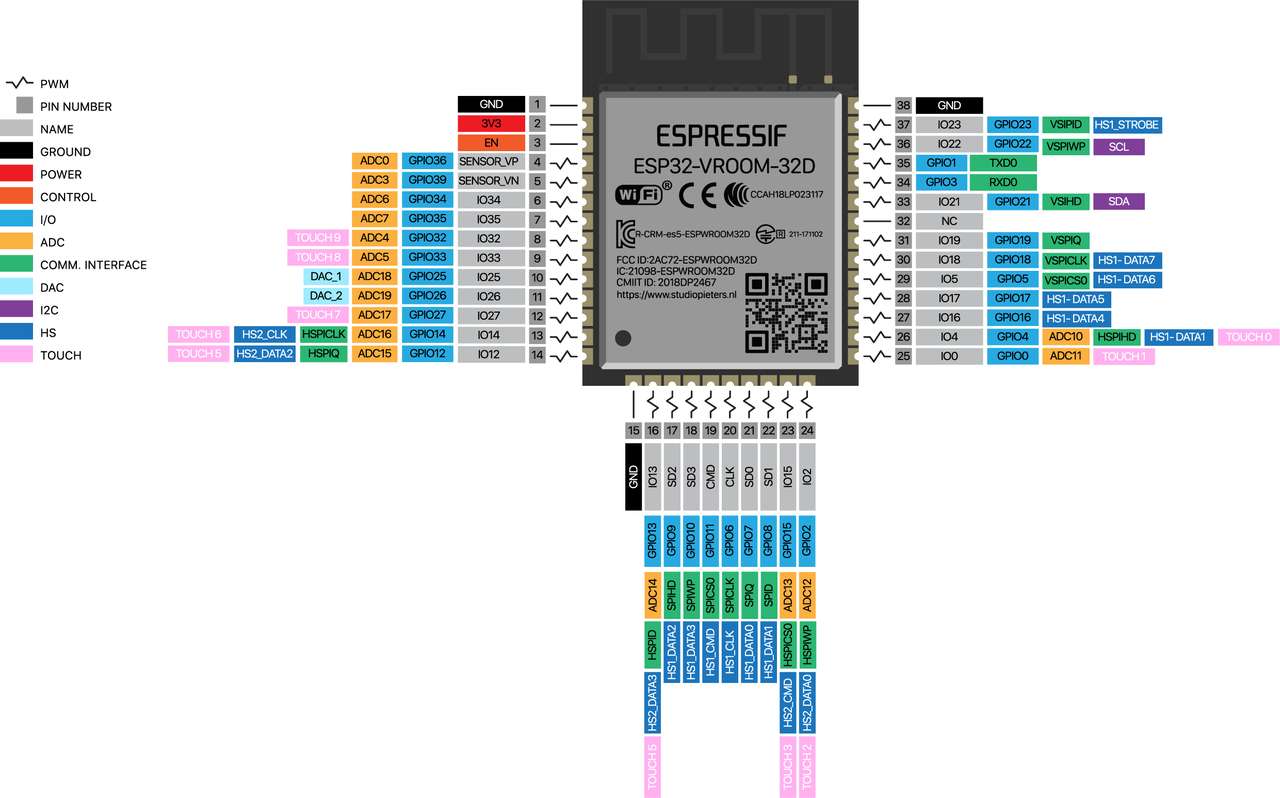
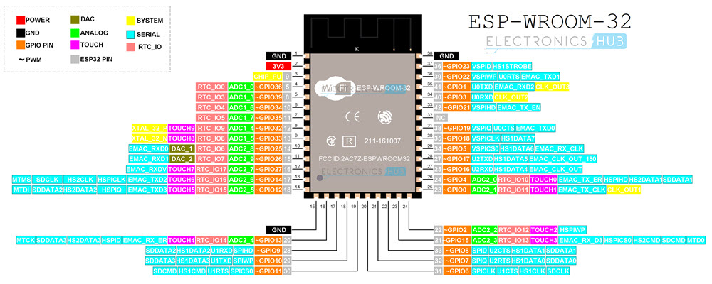
A Tiny Pug Board
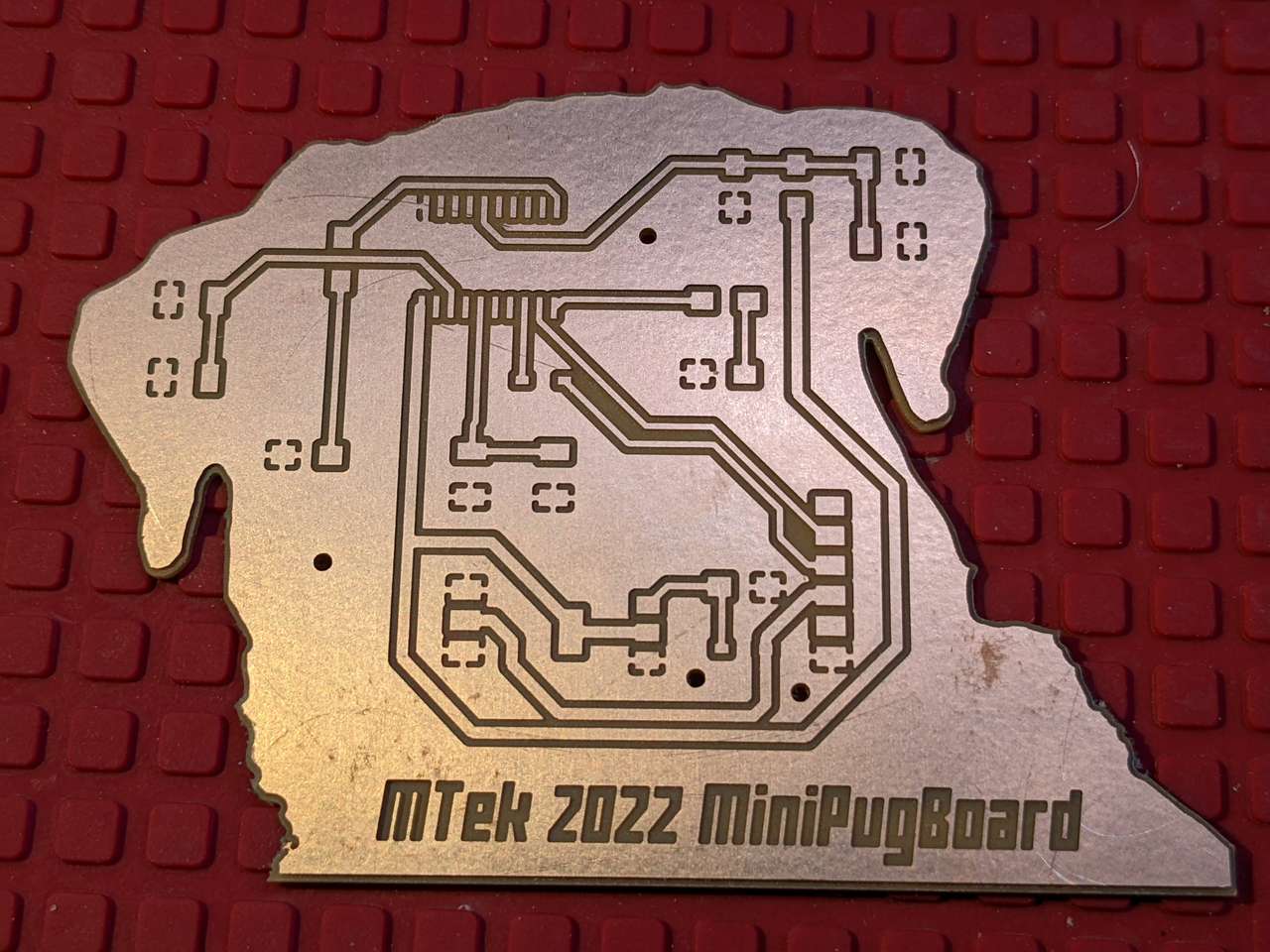
I have been using only ESP32 microcontrollers for my custom designed and fabricated boards up to this point. Since this assignment requires working with two different microcontroller series or types I decide to try out an ATtiny microcontroller! I made a new version of my PugBoard using the ATtiny 3226 microcontroller instead of an ESP32. I designed the board in KiCad.
Circuit Board Fab
CAM
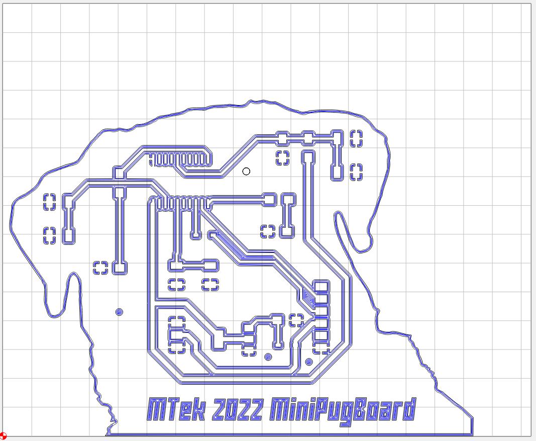
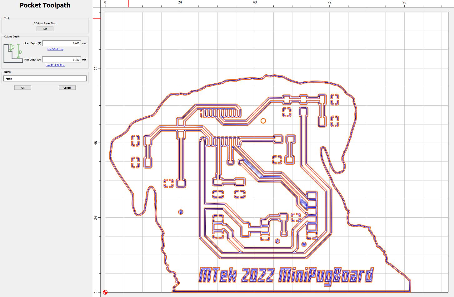
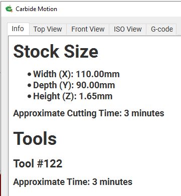
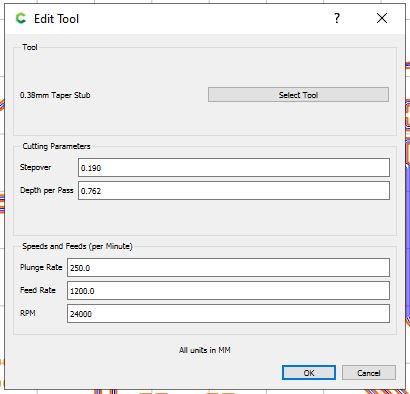
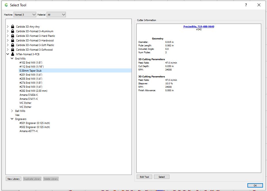
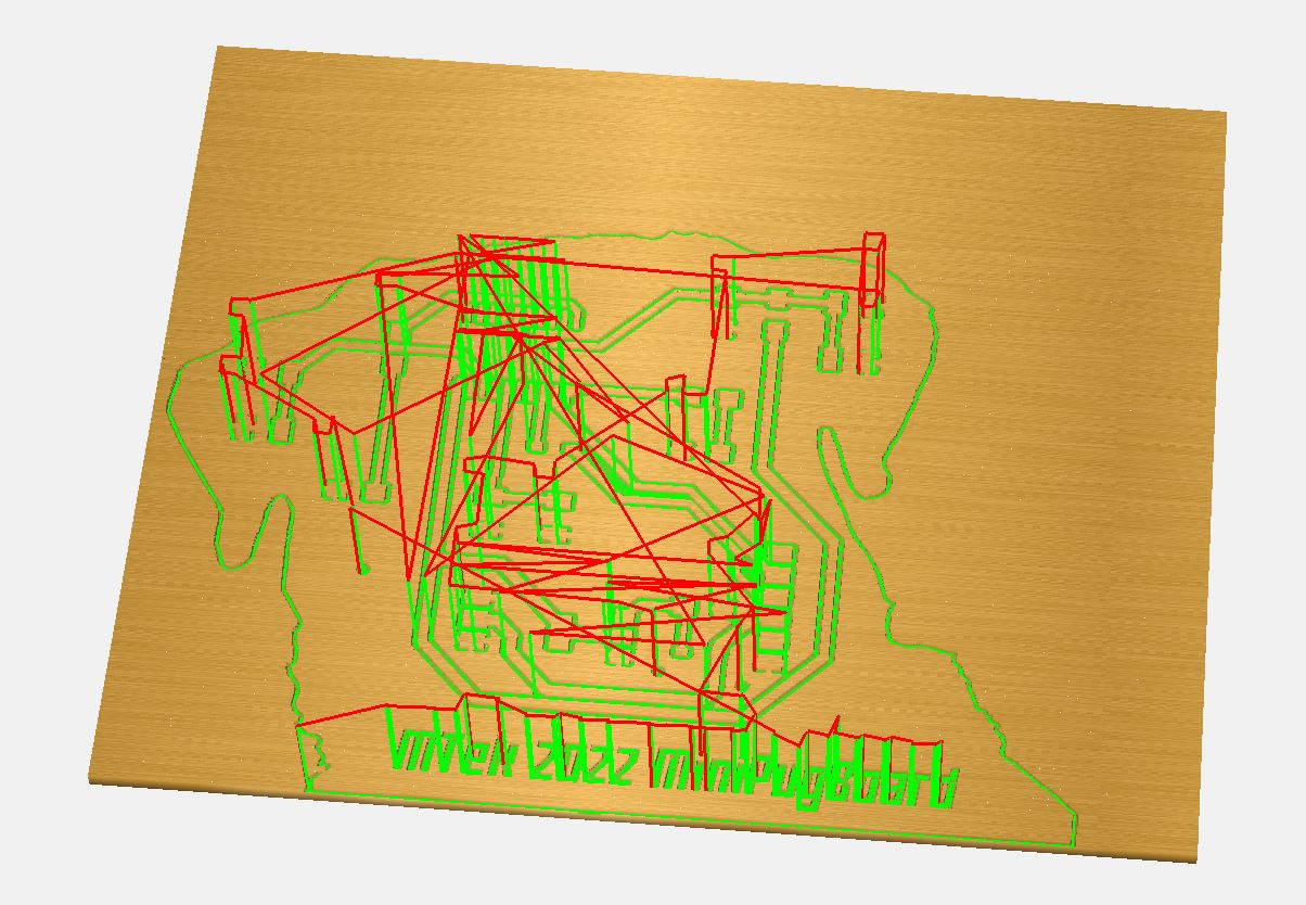
Above: I used Carbide Create CAM to set end mills, speeds and feeds and generate g-code for the Carbide 3D Nomad 3 mill.
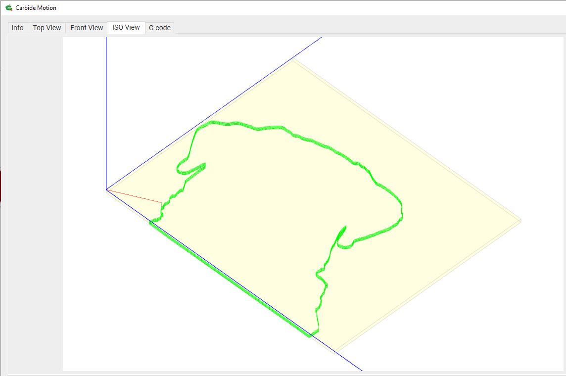
Milling
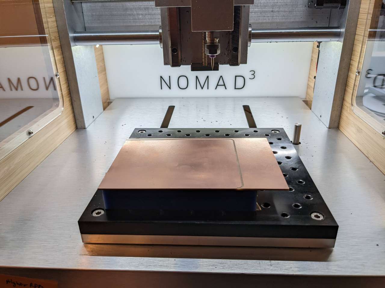
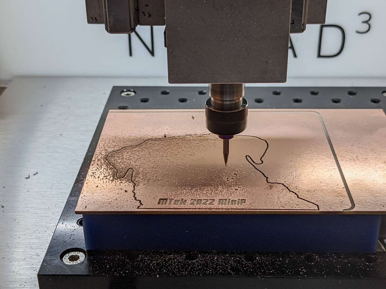
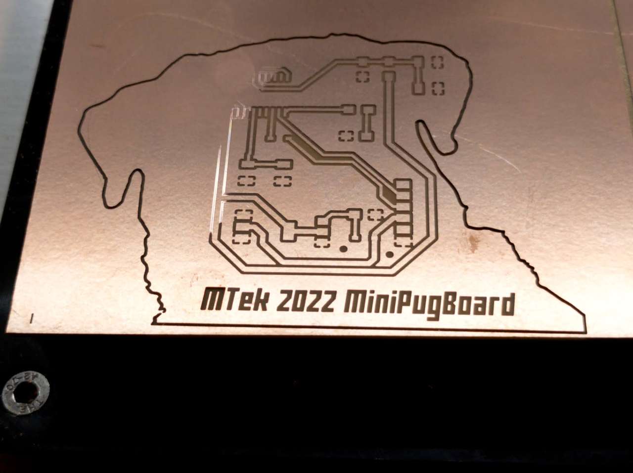

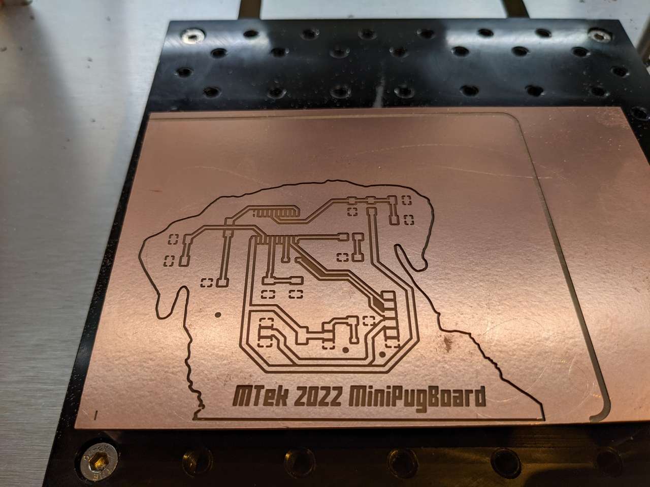

Above: I used Carbide 3D Nomad 3 mill to mill the Pug Board.
Interactive BOM
I once again used the wonderful Interactive BOM (iBom) plugin for KiCad to generate this:
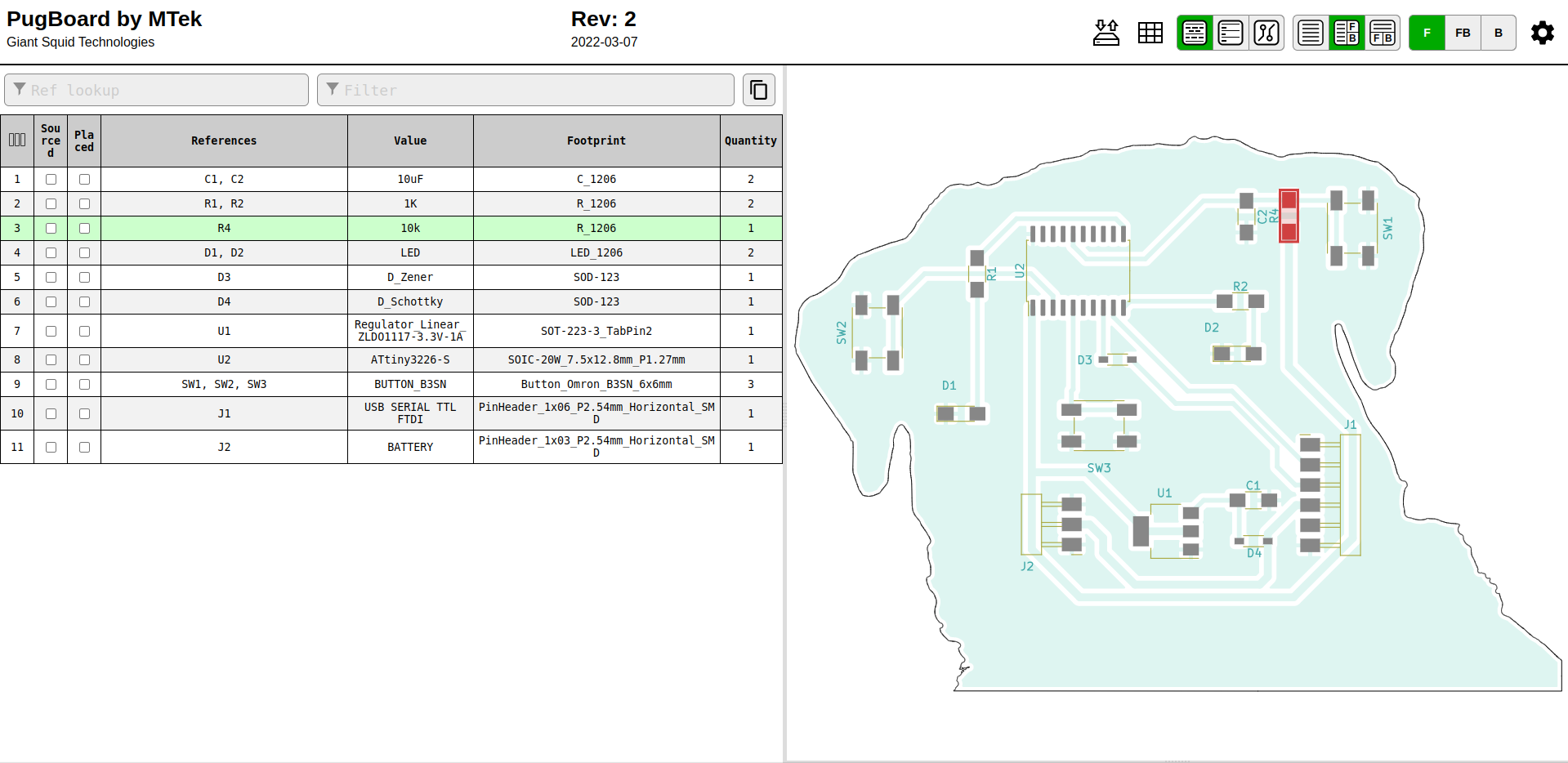 Above: Click image to access the HTML Interactive BOM (iBOM) generated by KiCad.
Stuffing
I used the iBOM to pick out components and place smaller parts first.
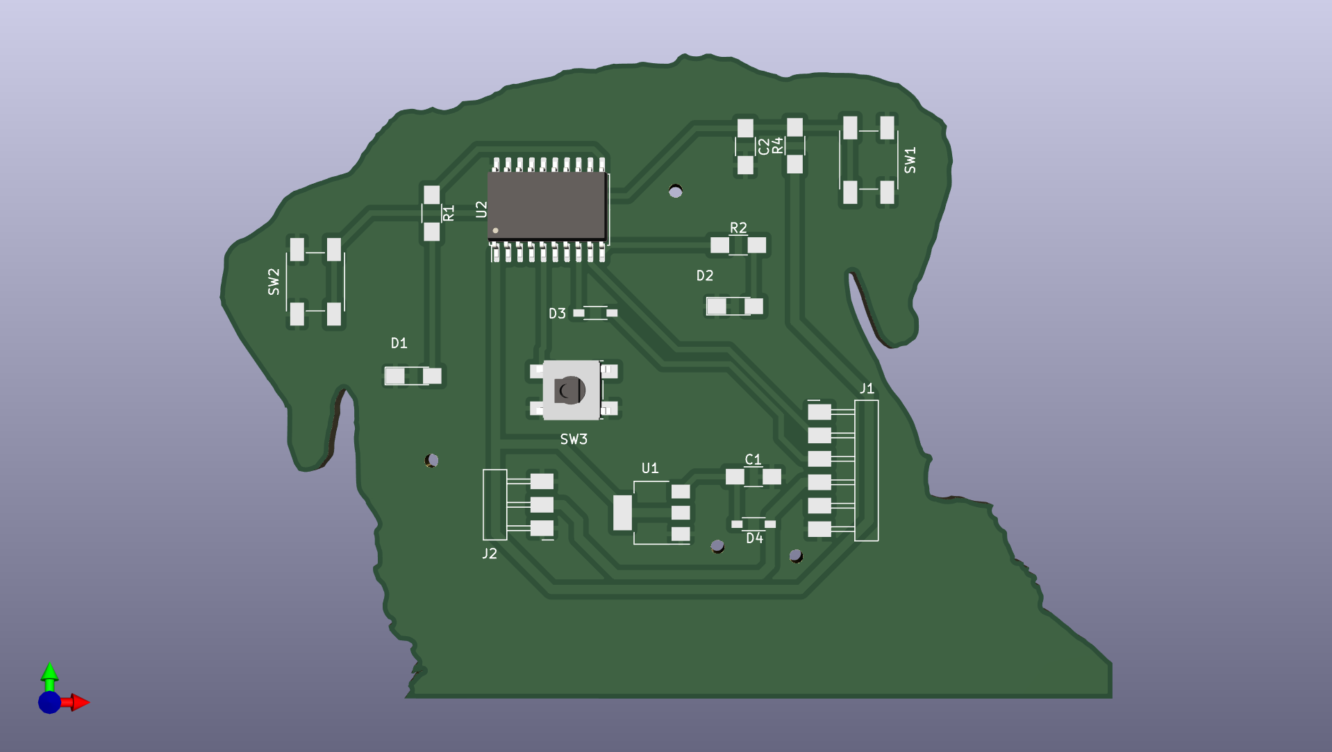
Above: I used the 3D image above from KiCad to determine the pin orientation of the ATtiny microcontroller with the dot on the package case determining pin 1.
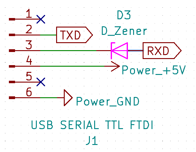
Above: I have been finding it’s easiest for me to look at the KiCad Schematic to quickly determine diode orientation, by looking at the line on the package and then on the diode symbol on the schematic. It would be even easier if the 3D model showed the diode case with line, but I wanted to move ahead without spending significant time adding all the 3D models to the package footprints.
Programming
I’m going to try to figure out writing code in the Processing language using the Arduino IDE 1.8.13, to control the ATtiny 3226 based TinyPug Board.
It seems like the megaTinyCore is a popular. I followed the install instructions atInstalling megaTinyCore. I used Arduino version 1.8.13 as recommended by the instructions:
This board package can be installed via the (Ardino IDE) board manager. The boards manager URL is:

http://drazzy.com/package_drazzy.com_index.json

1. File -> Preferences, enter the above URL in "Additional Boards Manager URLs"
2. Tools -> Boards -> Boards Manager... search for megaTinyCore then install 2.5.x DO NOT install 2.6.0!
3. Wait while the list loads (takes longer than one would expect, and refreshes several times).
4. Select "megaTinyCore by Spence Konde" and click "Install". For best results, choose the most recent version.
Next I selected:
- Tools, Board:, megaTinyCore, ATtiny3226…
- Tools, Chip:, ATtiny 3226
java.lang.NullPointerException
Shit! I don’t think I can program an ATtiny via serial. Maybe I need to set fuses to do this?
Reading the ATtiny 3226 datasheet I found the following out:
UPDI stands for “Unified Program and Debug Interface” it replaces In-system programming (ISP), AKA in-circuit serial programming (ICSP)
Page 15: 2.2 20-Pin SOIC, SSOP shows clearly Pin 16 is PA0 UPDI/RESET
Page 21: says “Connection for UPDI Programming” and shows that UPDI, VDD and GND are all that are needed.
Page 439: Starts the section “UPDI - Unified Program and Debug Interface” and shows that UPDI protocols that are different than used in ISP.
I should have read the programming sections of the datasheet more carefully! The ATtiny3226 is well tiny, and having the cool single pin UPDI is really quite slick! I also remember Neil and other instructors talking about UPDI needing only one pin for programming. Doh!
Also I had looked at the ATtiny microcontroller comparison chart on Wikipedia and it clearly shows that UPDI is the only option for Pgm Dbg on all 0,1 and 2 series ATtiny chips including of course the ATtiny3226 which is a 2-series chip.
Since I cannot program the ATtiny3226 via a serial port I will need to one wire to pin 16 PA0 (UPDI/RESET) and graft it onto my existing Tiny Pug Board, like opening Data’s head to program him in Star Trek. However, I don’t have a UPDI programmer :(
Not to worry Quentin Bolsee has one I can make one! SAMD11 dual serial, by Quentin Bolsee
I documented the process of making Quentin Bolsee’s SAMD11 dual serial board on my projects page.
Above is the graft wire to pin 16 PA0 (UPDI/RESET) I soldered on my Tiny Pug Board 20-Pin SOIC ATtiny3226
Above is how I wired the UPDI SAMD11 dual serial programmer to the Tiny Pug Board
Now to try programming again!
I didn’t have luck getting the UPDI SAMD11 dual serial programmer board to program. So…
I contacted Alan Han and asked him if he had a programmer. He did, actually an ATMEL ICE that I had forgotten I had borrowed to him. Alan dropped the ICE off at my place and I tried it out.
Atmel ICE programming via UPDI
Page 40 of the Atmel-ICE User Guide shows the pin outs to program via UPDI
I plugged the jumpers into my TinyPug board and tried programming again:
Same error!
I need help. I sent the following message to my local and global instructors and to my fellow remote classmates:
“I’m having a lot difficulties programming both Sam D and attiny chips with the ATMEL ice. Would anyone be able to help me at all today? “
I should also post this on mattermost Fab Academy messaging.
The datasheet on the Atmel ICE is very confusing about the connector pinouts. This persons site cleared that right up: CONNECTING THE Atmel-ICE PDI CONNECTOR
On a video conference call with Alan Han he suggested looking at the pinouts here to help me: Programmer UPDI D11C
I gave up on trying to program my board with the ATMEL ICE.
Serial to UPDI Programming
Talking again with Alan Han, he mentioned Serial to UPDI Programming with a standard FTDI cable and the Arduino IDE.
Alan sent me a link to the Git Programmer Adapter Serial to UPDIby Krisjanis Rijnieks. Fabricating my version of the board and the process of installing the SerialUPDI software By Quentin Bolsee and Spence Konde are documented on my project page: Programmer Adapter Serial to UPDI
Once I completed the project above, I met with my fellow fab academy student, Alan Han, via Signal video conferencing and he helped make sure I was connecting items up properly. When hooking up my wiring, I realized that the Resistor Capacitor circuit I had on Pin 16: PA0 (UPDI/RESET) for the reset button I had in my circuit, may have been interfering with UDPI Programming. I de-soldered the capacitor and resistor just to be sure.

Above: Resistor and Capacitor removed from Physical Pin 16: PA0 (UPDI/RESET)
Important Note I wonder if I went back and tried the other programmers if they would now work with this resistor and capacitor removed? That would be spiraling to wide at this time. I may come back and document this in the future.
Blink Sketch
I modified the Arduino tutorial blink sketch example code below with Alan’s help and then tried uploading the following Program using the Arduino IDE 1.8.13:
/*
  Blink

  Turns an LED on for one second, then off for one second, repeatedly.

  Chip: ATtiny3226
  Clock: 20MHz Internal
  Programmer: jtag2updi (megaTinyCore)

  Pin mapping: https://github.com/SpenceKonde/megaTinyCore/blob/master/megaavr/extras/ATtiny_x14.md

*/

#define LED_BUILTIN 9 //Sotware Pin 9 PB0 (Physical Pin 11)
#define LED_LEFT 8 //Softare Pin 8 PB1 (Physical Pin 10)

// the setup function runs once when you press reset or power the board
void setup() {
  // initialize digital pin LED_BUILTIN as an output.
  pinMode(LED_BUILTIN, OUTPUT);
  pinMode(LED_LEFT, OUTPUT);
}

// the loop function runs over and over again forever
void loop() {
  digitalWrite(LED_BUILTIN, HIGH);   // turn the LED on (HIGH is the voltage level)
  digitalWrite(LED_LEFT, HIGH);   // turn the LED on (HIGH is the voltage level)
  delay(1000);                       // wait for a second
  digitalWrite(LED_BUILTIN, LOW);    // turn the LED off by making the voltage LOW
  digitalWrite(LED_LEFT, LOW);    // turn the LED off by making the voltage LOW
  delay(1000);                       // wait for a second
}
… and the following verification line appeared in the Arduino IDE Output Pane!
pymcuprog.programmer - INFO - Write complete.
… and …
Pug Board Hero Shots
… Above: The LED eyes of my Pug Board blinked on and off! Awesome!
Above: I then added the b/w laser printed paper pug face overlay. You can download the same pug image from Wikimedia Commons Pug portrait.jpg by John Attebury
Later I hope to write new code that makes the Pugs eyes fade in and out with PWM when his nose button is pressed.
ESP-32
Programming with MicroPython
To learn how to program in MicroPython I used my board from the Input Devices Assignment. Please see that assignment for full details on how I designed and fabricated and trouble shot my GimbalDuo Board. The version below is a short version without trouble shooting.
GimbalDuo Board
I used Sara and Rui Santos’ excellent guides at Random Nerd Tutorials to learn about reading analog values from the potentiometer sensor gimbals:
I have used some excellent esp32 pin guides in the past, but the one at randomnerdtutorials is the best I’ve seen so far! ESP32 Pinout Reference: Which GPIO pins should you use?
ESP32 ADC – Read Analog Values with Arduino IDE
I decide it was time to try a different coding language: MicroPython.
I found this tutorial on MicroPython useful: ESP32/ESP8266 Analog Readings with MicroPython
To work with MicroPython I tried out Thonny IDE. I used the Linux Mint Software Manager to install Thonny. I tried uPyCraft as well but it was difficult to install so I stopped and moved ahead with Thonny.
I also needed to install python 3, esptool and stuptools, but when I went to my Linux Mint software manager both were already installed, probably from installing expresif dev software in previous assignments.
Next the guide said to run the esptool command, i typed the following into terminal:
python -m esptool
A bunch of expected text resulted showing that esptool was working:
esptool.py v4.1…
Next I plugged in my ESP32 GimbalDou board and flashed it with the MircoPython firmware:
The guide said:
If you are putting MicroPython on your board for the first time then you should first erase the entire flash using:
esptool.py --chip esp32 --port /dev/ttyUSB0 erase_flash
From then on program the firmware starting at address 0x1000:
esptool.py --chip esp32 --port /dev/ttyUSB0 --baud 460800 write_flash -z 0x1000 esp32-xxlatestrelease.bin
replace the “esp32-xxlatestrelease.bin” with the latest release .bin file downloaded on the the bottom of the page above, or use the file linked in the files section of this page. Remember that you need to reset your esp32 board to be programmed by pressing and holding the prog button and then pressing and releasing the reset button, then releasing the prog button.
during the command above the following was displayed:
esptool.py v4.1
Serial port /dev/ttyUSB0
Connecting......
Chip is ESP32-D0WD (revision 1)
Features: WiFi, BT, Dual Core, 240MHz, VRef calibration in efuse, Coding Scheme None
Crystal is 40MHz
MAC: ac:67:b2:d5:85:10
Uploading stub...
Running stub...
Stub running...
Erasing flash (this may take a while)...
Chip erase completed successfully in 16.9s
Hard resetting via RTS pin...
Next I ran the command to install the latest MicroPython firmware to the esp32:
esptool.py --chip esp32 --port /dev/ttyUSB0 --baud 460800 write_flash -z 0x1000 esp32-20220618-v1.19.1.bin
during the flash command above the following was displayed:
esptool.py v4.1
Serial port /dev/ttyUSB0
Connecting.....
Chip is ESP32-D0WD (revision 1)
Features: WiFi, BT, Dual Core, 240MHz, VRef calibration in efuse, Coding Scheme None
Crystal is 40MHz
MAC: ac:67:b2:d5:85:10
Uploading stub...
Running stub...
Stub running...
Changing baud rate to 460800
Changed.
Configuring flash size...
Flash will be erased from 0x00001000 to 0x0017efff...
Compressed 1560976 bytes to 1029132...
Wrote 1560976 bytes (1029132 compressed) at 0x00001000 in 25.2 seconds (effective 495.6 kbit/s)...
Hash of data verified.

Leaving...
Hard resetting via RTS pin...
Next I had to find what port my ESP32 was connected to, using the Arduino IDE I went to tools, port and found that my port was /dev/ttyUSB0 Not sure why this is needed, I moved onto the next task.
Next I ran the MicroPython script replacing the given pin with the GimbalDuo GPIO 04 which is simply pot = ADC(Pin(04)) in MicroPython.
# Complete project details at https://RandomNerdTutorials.com

from machine import Pin, ADC
from time import sleep

pot = ADC(Pin(04))
pot.atten(ADC.ATTN_11DB)       #Full range: 3.3v

while True:
  pot_value = pot.read()
  print(pot_value)
  sleep(0.1)
I cut and pasted the code into Thonny IDE. Next in Thonny I selected “Run” “select interpreter” and then selected: “MicroPython (ESP32)”” and Port: “”…()/dev/ttyUSB0)…”” hmm that’s why they wanted me to get the port above!
Next I pressed the reset button on the GimbalDou board while it was plugged into the USB port. This triggered the Shell window to respond with confirmation:
rst:0x1 (POWERON_RESET),boot:0x12 (SPI_FAST_FLASH_BOOT)
configsip: 0, SPIWP:0xee
clk_drv:0x00,q_drv:0x00,d_drv:0x00,cs0_drv:0x00,hd_drv:0x00,wp_drv:0x00
mode:DIO, clock div:2
load:0x3fff0030,len:4540
ho 0 tail 12 room 4
load:0x40078000,len:12344
ho 0 tail 12 room 4
load:0x40080400,len:4124
entry 0x40080680
MicroPython v1.19.1 on 2022-06-18; ESP32 module with ESP32
Type "help()" for more information.
Next I clicked the play button and got this via the Thonny IDE Shell while moving the gimbal:
2206
2207
2205
2203
2208
2203
1636
1275
1412
2220
2739
3955
4041
3029
2346
1388
528
529
944
2893
4095
4095
3711
2777
1695
927
526
523
511
509
510
525
524
528
528
528
528
516
510
530
527
522
519
507
517
526
1162
2652
4095
4095
4095
4095
4095
4095
4095
4095
4095
4095
4095
4095
4095
4095
4095
4095
4095
4095
4095
3745
2703
1649
688
518
506
499
499
499
496
496
496
496
496
496
496
496
496
496
496
496
496
509
1035
2295
3264
4095
4095
4095
4095
4095
4095
4095
4095
3723
2367
1157
505
505
505
503
501
499
499
497
497
539
1728
3439
4095
4095
2205
2206
2207
2207
2204
2208
2206
2206
2206
2208
2208
2207
2208
2203
2206
2206
Holy Frack! it works! Time to take a video
Hero Video
Above: Video of Thonny IDE MicroPython code for potentiometer gimbal input showing changing values with 11db of signal Attenuation via Thonny Shell
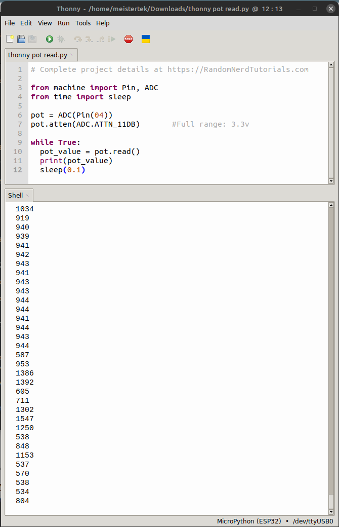 Above: View of Thonny IDE in use running the MicroPython code below.
code
MicroPython Code “esp32ReadAnalog.py” with comments explaining my understanding of the code.
# Complete project details at https://RandomNerdTutorials.com
# modified by Dan "MTek" Meyer 2022-Jul-31 Sun 9:44pm

from machine import Pin, ADC   #ADC=analog digital conversion
from time import sleep

pot = ADC(Pin(04))             #pick your boards GPIO pin
pot.atten(ADC.ATTN_11DB)       #Full range: 3.3v with x db signal attenuation

while True:                    #while loop forever?
  pot_value = pot.read()       #read the pot value
  print(pot_value)             #print pot value to shell
  sleep(0.1)                   #pause x.x seconds between reads
ESP-32 PugBoard
NOTE This board was too complex for this assignment. I should have read the assignment more carefully, it was not required to design a new board. So I abandoned this board and made a simpler ATtiny based version of this board documented above.
The ESP-32 PugBoard below was a more advanced version of the PugBoard that used an ESP-32 chip. However I mistakenly re-zeroed my mill and milled off traces by mistake. At the time I had no large circuit board milling blanks on hand, so I abandoned the project. I may revisit making this board after graduation.
However, I learned a lot working on my ESP-32 based ESP-32 PugBoard documented below, that was relevant to this assignment.
END NOTE
I wanted to make a custom shape board, so I found this great video on that: ADVANCED PCB GRAPHICS WITH KICAD 6 AND INKSCAPE
I wanted a pug shaped board. Pugs are one of may favorite dogs, so I found this pug photo at Wikimedia Commons.
| Function | Pin | Arduino |
|---|---|---|
| Reset SW1 | 3 | EN |
| Hold to program Button SW2 | 25 | GPIO0 |
| Summon Demons Button SW3 | 7 | GPIO35 |
| Evil Eye LED D1 | 8 | GPIO32 |
| Evil Eye LED D2 | 8 | GPIO16 |
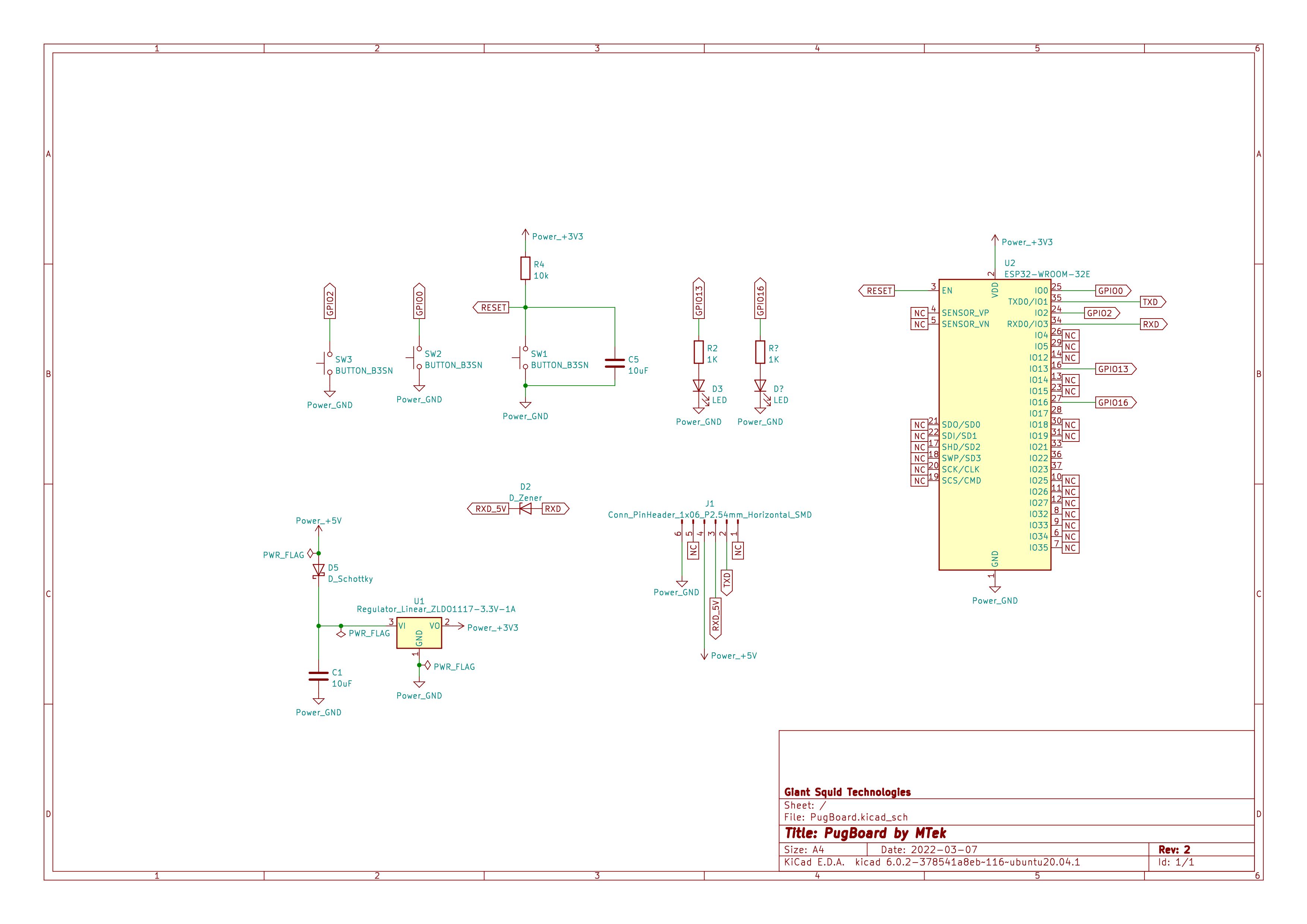 In KiCad 6 I laid out my schematic. Note pins and GPIO’s on this schematic were later changed.
Next was KiCad PCB Editor. I added a board Edge.Cuts outline by importing an SVG I created by tracing photo I cleaned up in Gimp. The new SVG import art work and export SVG functions in KiCad 6 are awesome!
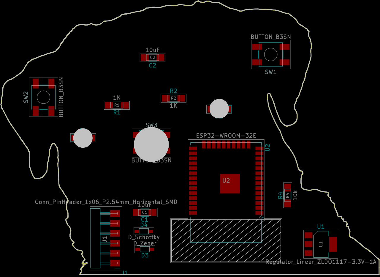 Here is my board with the components I dragged in place before routing traces.
I was being driven nuts by unconnected pins, well in Schematic Editor you simply select the X– icon called Add a no-connection flag or press the q key. This change also resulted in a proper design rules check.
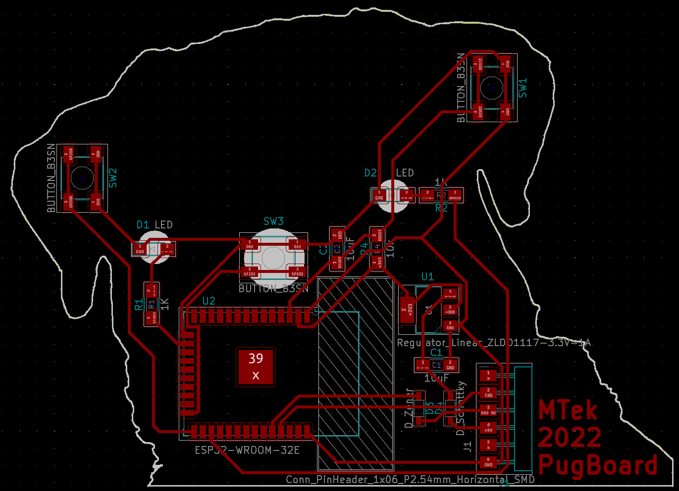 Here is my board after a few hours of routing tracks.
I then went on to “Perform Electrical Rules Check” and had errors. I watched the 2021 Electronics Design with KiCad by Aalto Fab Lab This helped me get ready for the KiCad PCB editor. I also learned that a Global Label can be added called NC and set as a passive component for any pin that is not not connected. I also learned that you can use the Schematic Editor / Preferences / Manage Symbol Libraries / Global Libraries and Project Specific Libraries tabs, Migrate Libraries button to convert a libraries from legacy to the “KiCad” 6.x format.
Next I used Inventables free Easel software to mill the traces of my PugBoard on a 500x500mm bed X-Carve, using the following settings:
| Machine | Feed Rate | Speed | Plunge Rate | Cut Depth | Tool | TIR |
|---|---|---|---|---|---|---|
| X-Carve 500x500mm | 1168 mm/min (46 ipm) | 12,000rpm | 508 mm/min (20 in/min) | 0.10mm (.004 in) | PreciseBits Taper Stub End Mill 0.38mm (0.0150”) dia, 2 Flutes | 0.4mm (.0015 in) |
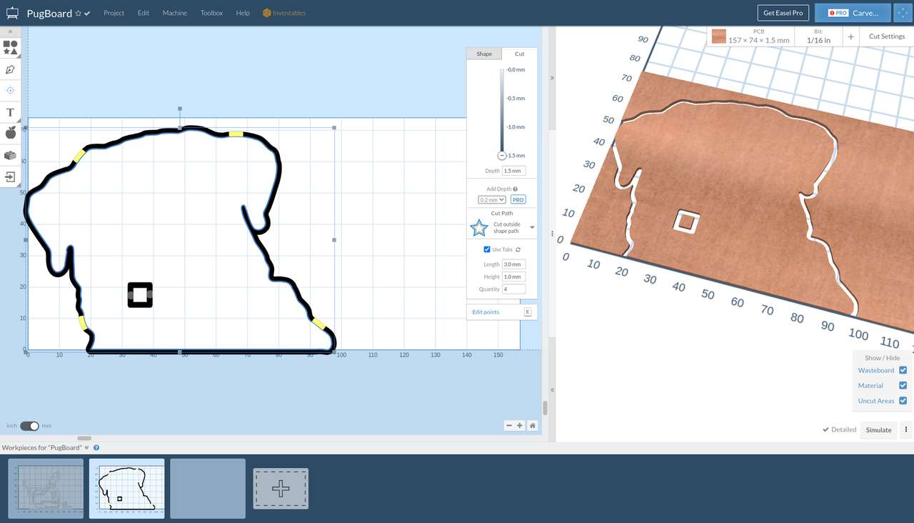 Then I cut the outline.
| Machine | Feed Rate | Speed | Plunge Rate | Cut Depth | Tool | TIR |
|---|---|---|---|---|---|---|
| X-Carve 500x500mm | 200 mm/min | 12,000rpm | 100 mm/min | 0.50mm | End Mill 1.6mm dia, 4 Flutes | 0.4mm (.0015 in) |

 I did my first mill of traces, but I made a mistake and did not set my depth of cut deep enough to remove the copper around my traces.
Milling off traces! :(
Then I made an even bigger mistake, and re-zeroed my Y axis slightly off from my initial cuts. This caused me to mill off some of my traces :(
One interesting trick I learned was to remove unused pads on the ESP32 you may (press ‘E’ with the cursor over the pad) and under “Layers” change it from “All copper layers” to “B.Cu”. This allows more space to route traces under the ESP32 package. Just remember to cover those traces with kapton tape to insulate them from the ESP32’s legs.
Compare the performance and development workflows
Development workflows
Using the Development workflows above I felt that:
The ESP-32 was ok to program with a simple USB to TTL Serial adapter cable. However designing a board for an ESP-32 is quite a bit more difficult due to the number of pads on the ESP-32 MCU. The Thony IDE was easy to install in Linux Mint (Debian) with the bash install script suggested at Thonny Wiki, Linux, Installing. However the MicroPython firmware install process was a somewhat complex extra step that was not required with The ATtiny 3226 and Arduino.
The ATtiny 3226 was easy to design a board for in KiCad. However, since I mistakenly put an Resistor Capacitor circuit on the RESET pin, that was also the UPDI programming port, a lot of trouble shooting was done before he realized the problem. Once the Resistor Capacitor circuit was removed, and the required resistor was in place per the programming with the Arduino IDE was quite easy.
There was a bit of one time command line setup using SerialUPDI software to get the USB to TTL Serial adapter by FTDI to speak the UPDI protocol to program the ATtiny 3226 via the Arduino IDE. But this process was easy.
The ATtiny 3226 was also easy to use without having to learn how to set fuses, which I needs more time to fully understand.
Personally I like the ESP-32 MCU design and programming workflows better, but that may because I have spent more time reading ESP-32 data sheets, and have used the ESP-32 in more projects. I think for most people it would be much easier to start with the ATtiny 3226 and Arduino IDE.
Performance
Both the ESP-32 and ATtiny 3226 were more than fast enough for this assignment. However the ESP-32 was surprisingly easy to program. The fact that the ESP-32 can be programmed initially with a simple low cost USB to Serial converter cable is great. Also once the ESP-32 is programmed to connect to WiFi it can be programmed that way with no physical cables needed going forward. However ESP-32 MCU’s are quite a bit more expensive than ATtiny MCU’s
The ATtiny 3226 is a great low cost MCU and it is easy to program if no circuits are placed on the RESET/UPDI pin, except the resistor, or better yet a diode, that is required per the megaTinyCore and SerialUPDI documentation.
References
Aalto Fablab: Setting up MegaTinyCore