8. Computer controlled machining
Assignment
| Have you? | Done |
|---|---|
| Group assignment | ⬇ |
| Complete your lab’s safety training | Yes |
| Test runout, alignment, speeds, feeds, and toolpaths for your machine | Yes |
| Document your work to the group work page | Yes |
| and reflect on your individual page what you learned | Yes |
| Individual assignment: | ⬇ |
| Make (design+mill+assemble) something big | Yes |
| Include your design files and hero shot photos of the final object | Yes |
Learning outcomes
| Have you? | Done |
|---|---|
| Demonstrate 2D design development for CNC production | Yes |
| Describe workflows for CNC production | Yes |
Checklist
| Have you? | Done |
|---|---|
| Linked to the group assignment page | Yes |
| Documented how you designed your object | Yes |
| Documented how you made your CAM-toolpath | Yes |
| Documented how you made something BIG (setting up the machine, using fixings, testing joints, adjusting feeds and speeds, depth of cut etc.) | Yes |
| Described problems and how you fixed them | Yes |
| Included your design files and ‘hero shot’ photos of final object | Yes |
FAQ
How big is big?
Answer: Big enough to show you understand many of the possibilities of CNC machining - drill, pocket, dog-bones, nesting, etc.
Dan: My foam glider will use all these and will be 1.2 meters in wingspan
Does it have to be wood or wood products?
Answer: No. But the lab is only responsible for providing you with a full size wood board.
Dan: My material will be Depron Extruded polystyrene Sheet 5.7 to 5.8 mm thick. I will supply my own foam sheet.
Large Format CNC Accessibility
I will complete this assignment using my ~$500 FoamCrawler CNC Router I designed and built for Fab Academy. I am asking my local and global instructors if I may complete Fab Academy using the FoamCrawler, as it can meet all of the make something big requirements. This will avoiding using a high cost CNC router costing in the range of $10,000.00 to $20,000.00. CNC routers and laser cutters in this price range exclude smaller fab labs and individuals from completing Fab Academy when access to a fully equipped Fab Lab is not possible or is difficult. A low cost machine like the FoamCrawler increases accessibility to Fab Academy. Increased accessibility is one of the core topics covered in the latest books on Fab Labs; Designing Reality
Fab Shop
I, and many other Fab Lab Gurus, personally strive to drive down the cost and space requirements for a set of fabrication capabilities typically found in a fully equipped Fab Lab costing over $100k. My Fab Shop concept is a set of build it yourself machines and a low cost computer taken from the scrap bin that aims to push the limits fabrication capability in small space and budget. The Fab Shop concept empowers an individual, or small group of people, to start their own Fab Shop with almost full Fab Lab capabilities, in a spaces like an urban apartment or small garage.
1.2 Meter Chuck glider (Meets make something big requirements)
Since my local instructor said my project was not meter scale and big enough I decide to use the machine I designed, The Foam Crawler to make a 1.2 meter wing span chuck glider from foam sheet.
The glider will include all the things I need to learn during this assignment. I will also test slot and tab joint fits, by measuring and test fitting parts, although foam sheet is forgiving in this area.
Safety training
For the FoamCrawler there are procedures that must be followed:
- Make sure the spindle is moved to where you want to start your cut on the foam sheet
- Set x,y,Z zero with a $ home command.
- Test feed the foam sheet completely forward and back to the edge of the rollers, to make sure there is enough space for the sheet to move.
- Use the front power switch, or power strip switch to shut off the machine in an emergency.
- Wear safety glasses, router bits may break or shatter especially if crashed into solid parts of the machine.
- Wear a dust mask, foam dust particulate can irritate your lungs
- Make sure to have adequate ventilation, foam can out gas fumes when cut or if burned by impropper speeds and feeds.
- Have a fire extinguisher ready, any process that creates dust and heat, such as routing an milling is a potential fire hazard
- Be aware of sources of ignition, such as brushed electric motors in power drills, gas fired water heaters, gas stoves, vacuums with brushed motors.
- Immediately sweep up all dust after each part is milled.
Documentation of processes
Materials Machined
- Depron Extruded polystyrene Sheet 5.7 to 5.8 mm thick (sometimes difficult to source in USA)
- FOAMULAR® Fanfold DWB extruded polystyrene foam 5.1 to 5.4 mm thick (at most home improvement stores)
- DOW Protection Board III extruded polystyrene foam 5.1 to 5.4 mm thick (difficult to source, may be obsolete)
Test Machine Capability
In Onshape CAD I designed a Foam Test Plate to cut on the Foam Crawler CNC. This test plate would allow dimensional capability to be checked. If needed Steps per mm factors may need to be adjusted, especially on the roller based y-axis where slip can occur. The conservative feed rates in the next section were used to reduce the chance of the cutter feed pushing and pulling the foam sheet out of the grip of the rollers.
 Above: Onshape Foam Test Plate design
 Above: Onshape Foam Test Plate design SVG imported and simplified in Inkscape. It’s very important to verify that the actual objects are exactly the right size before moving to CAM. Download the SVG image / file above to generate cam for your own machine.
 Above: SVG dimensioned drawing export from Onshape, dimensions will be checked with calipers after machining. Download this file to check your own machine.
speeds and feeds
All cuts were completed with to following two sets of settings: PreciseBits 1.6mm diameter fish-tail, diamond-cut router bit spun at 6,000 to 12,000 RPM with a 48VDC 400Watt DC Spindle Feed rate X & Y: 1200 & 2400mm/min Plunge rate Z: 230 & 1200 mm/min Depth per pass: 7mm (single pass) Spindle RPM 6000 and 12000
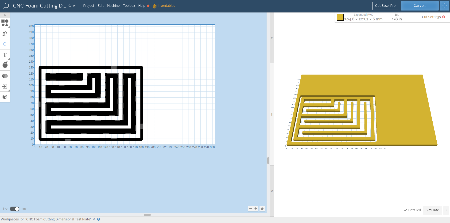
Above: Inkscape SVG imported into Easel CAM. One layer should have been eliminated in inkscape before import. No worries…

Above: Easel CAM. Toolpath depths and 3D preview generated. Unneeded toolpaths were deleted.
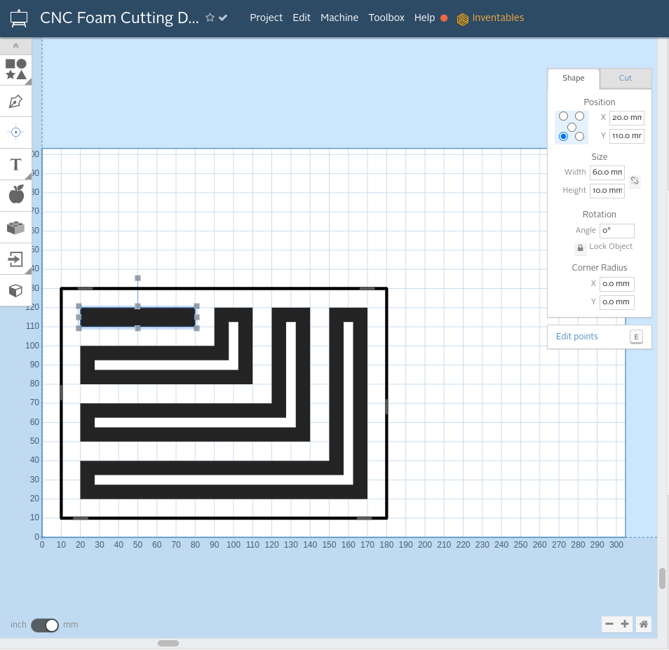
Above: Easel CAM, verifying that dimensions are correct.
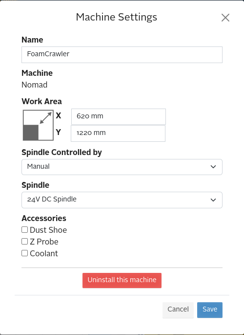
Above: Easel CAM Machine Settings
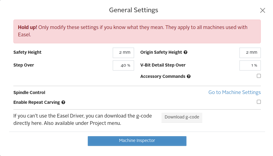
Above: Easel CAM General Settings, note Download g-code button, this will be used to send the g-code to the Foam Crawler via WiFi.

Above: Easel CAM, Pocket milling toolpath operation 1 on it’s own workpiece.

Above: Easel CAM, perimeter cutout toolpath operation 2 on it’s own workpiece.
Now onto milling the Foam Test Plate to check:
Preparation
To get ready to mill the Foam Test Plate.

Above: I inspected my ~ 5-6mm thick foam sheet material, black Depron was very flat. The DOW Protection Board III extruded polystyrene foam insulation with plastic film on one side. The DOW Protection Board III was wavy and the peak to valley measurements varied from 0.3 to 0.8 mm. Note that if the rollers are parallel with waves the Z height may be maintained relative to the wavy surface.
For application where flatness is important to function, Depron foam should be used. In most prototype RC aircraft and template applications DOW Protection Board III is a good low cost option.

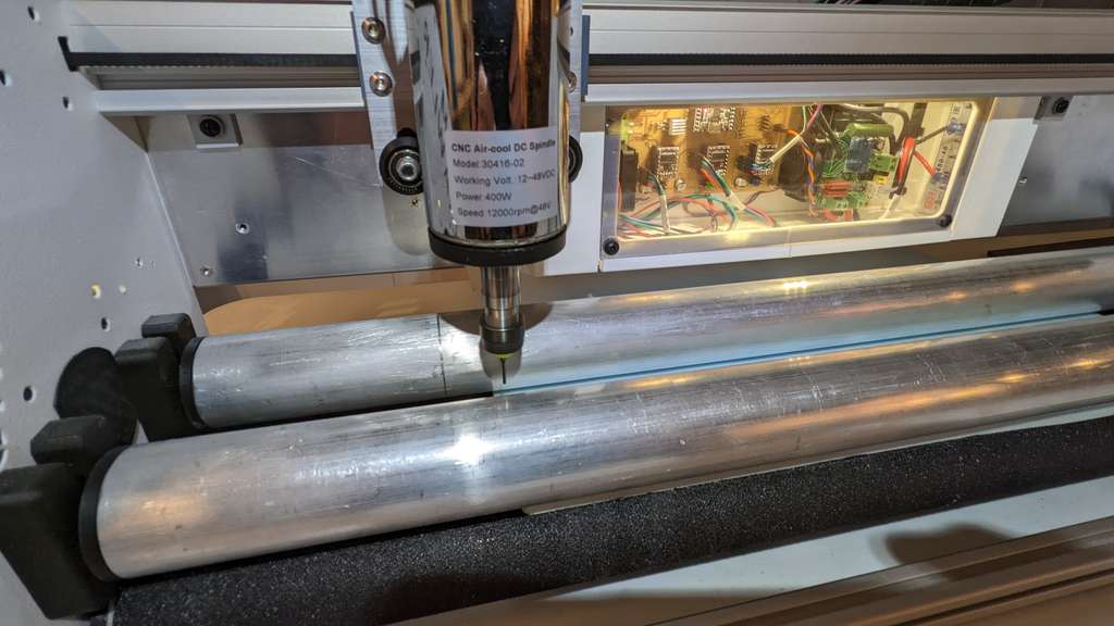
Above: The cutter flute depth covers the material thickness well. However wavy materiel may cause rubbing on the cutter shank.
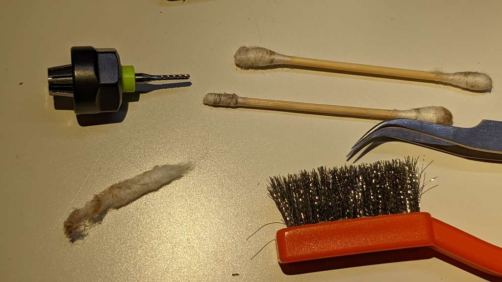
Above: I made sure that the collet, throat, nut and tool were very clean. Even a small bit of dirt can cause the tool to shift slightly leading to runout. I was surprised how much dirt there was on the surfaces of the tool holders.

Above: I wore my magnifier safety glasses, to protect my eyes.

Above: I checked for clearance with the foam sheet driven all the way forward.

Above: I checked for clearance with the foam sheet driven all the way back.
Above: Next I zeroed the bit in X and Y directions
I then touched off with the end mill on the surface of the foam, and zeroed Z.
Milling
I then started milling and the first few pockets machined well. However the cut suddenly became oddly silent. I paused the machine and inspected the end mill, this is what I saw:

Above: weird stringy bits of foam membrane twisted around the end mill.

Above: Retracting the end mill it was clear that the plastic membrane on one side of the foam had melted running the spindle at 12,000 rpm. I cleaned the bit and lowered the spindle rpm to 6,000 rpm. the rest of the cuts went well.
I also realized that I should load the DOW foam with the thin plastic membrane facing down. I think sometimes, with membrane facing up, the waves in the foam push the membrane up onto the shank of the tool and it melts quickly. If the membrane is placed down it is always on contact with the diamond-cut cutting edges and does not melt.

Above: The rest of the cuts went well.

Above: View of the backside of the Foam Test Plate, the cut quality was high. a bit of fuzz on one edge is normal. However climb vs conventional cutting can be used if needed to give the smoothest edge on the used final part. for my RC aircraft application the fuzz does not impact the final items.
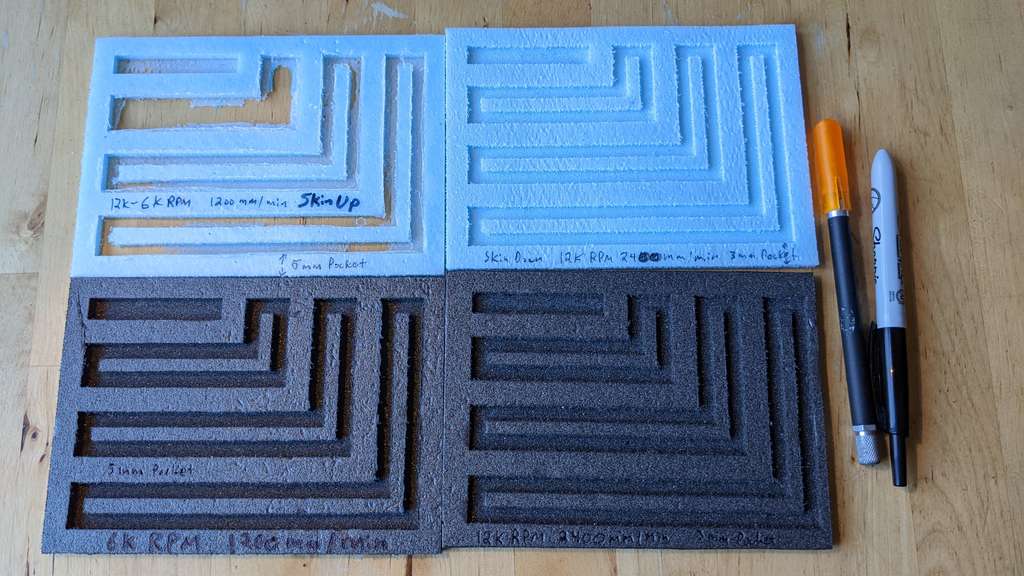
Above: 4 Foam Test Plates marked with speeds and feeds. 12,000 rpm at a feed of 2400 mm/min works as well as 6,000 rpm at 1200 mm/min. The higher rpm and feed rate saves significant machining time. Both 5mm and 3mm pocket depths were tested.
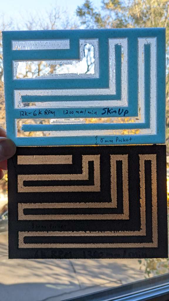
Above: The 5mm pocket depth revealed the limitations of the wavy DOW Protection Board III with some pockets cutting through the bottom. This makes me suspect that waves are as deep as 1 to 1.2 mm deep in some cases. The Depron foam did not have break through issues.
Above: The 3mm pockets of course did not break through, even on the wavy DOW Protection Board III

Above: The 3mm pockets of course did not break through, even on the wavy DOW Protection Board III
runout
Runout defined:
- Northland Tool: The Complete Guide to Spindle Runout: How to Test, Measure & Reduce
- CNC Cook Book: Measure and Reduce Spindle Runout [Tool Life Killer]
- Wikipedia: Run-out
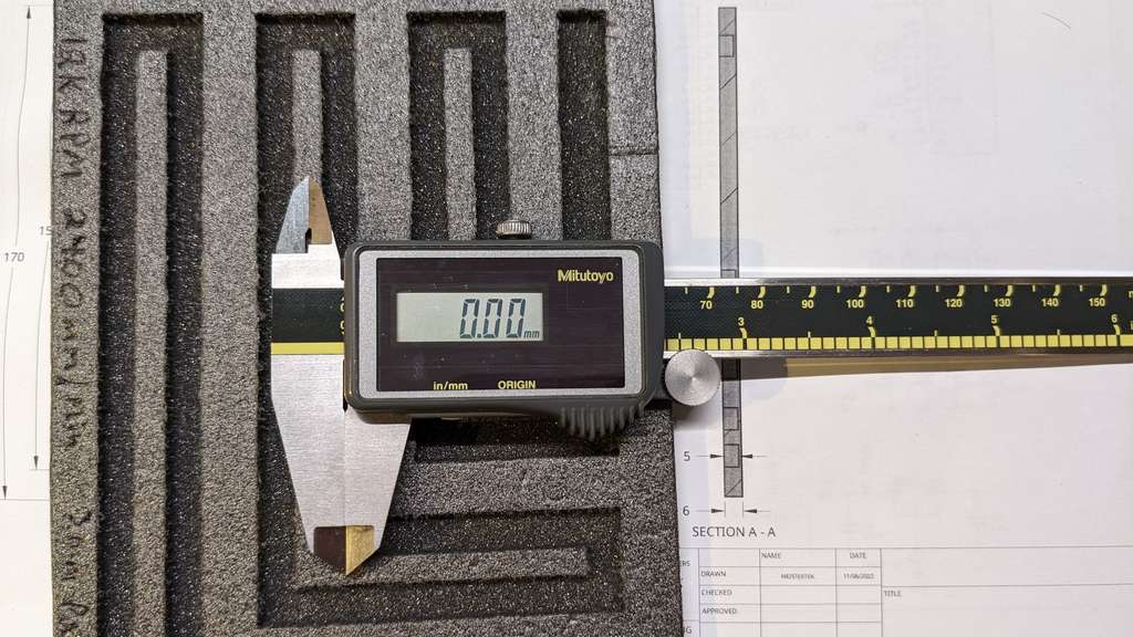
Before beginning measurements, I made sure my calipers were properly zeroed.


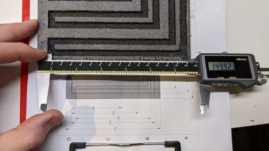
 Above: The measured dimensions of both the edges of the pocket and pocket islands showed no signs of runout. I did my best to engage the widest length of my caliper jaws and stopped as soon as I had a small amount of resistance. The resulting measurements show that the Foam Crawler is quite repeatable and accurate.
I think that some stiffer materials would need to be cut to truly test runout, but the Foam Crawler is made to cut foam and it does this well. The Foam Crawler has more than enough repeatability and precision for tab and slot construction to work well for my RC aircraft and high altitude balloon package applications.
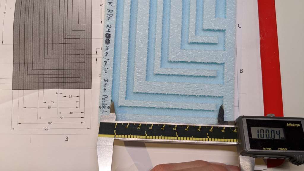
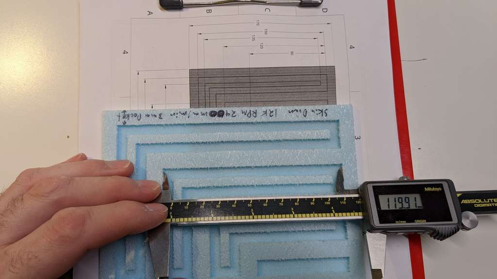
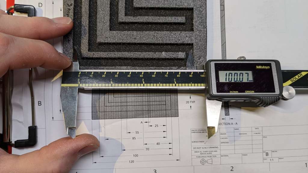
Measuring the slots above the measurements were:
X Direction Short 100.04 mm 10.03 mm 100.07 mm 10.06 mm
So it looks like a possible average + 0.05 mm runout may be present in the X direction. So it looks like a possible average + 0.05 mm runout may be present.
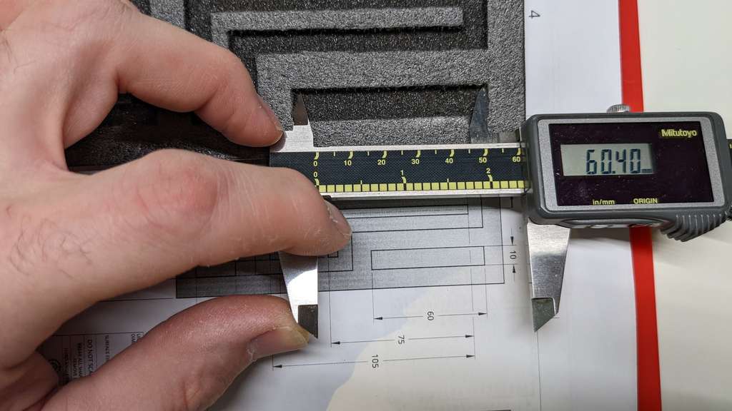
Y Direction Long 119.91 mm 149.94 mm 59.95 mm 149.92 mm 60.40 mm
One measurement 60.40 seems to be an outlier however and may be a measuring error. Eliminating that measurement, it looks like a possible average - 0.07 mm runout may be present in the Y direction.
Please NOTE However, measuring foam is susceptible to it being difficult to apply the same force between measurements of the foam slots and ridges. A more rigid material would need to be used to reduce the impact of caliper operator variability in these measurements. Even then a caliper is susceptible the the factors covered here: Mitutoyo: General notes on use of caliper
Alternatively a specialized thickness measuring tool for compressible materials would need to be utilized. These tools are beyond my current skills set and accessibility to use. Here is a good primer article about Gaging Compressible Materials in Modern Machine Shop Magazine.
Pin gauges and micrometers with a ratchet thimbles may be best to measure complete runout on harder plastic like materials.
Most students in Fab Academy only have control over how they load the end mill into the collet and how clean the collet and end mill surfaces are. They also have control over how tight they clamp the collet nut, but typically don’t have a way to measure this tightness. For milling large parts in wood what the control of these factors should be enough to prevent most runout issues and get repeatable runout values between end mill changes.
However, for milling with small diameter tools, such as those used in milling circuit boards, students and future fab in Fab Academy should also be taught how to measure Total Indicated Runout (TIR). I cover that procedure in my project area under ” Total Indicated Run-out (TIR) “. TIR allows runout of the just the tool, holder, and spindle to be checked. Measuring TIR of each rotating part of a spindle would students and fab lab managers to pin point the sources of runout of the complete spindle and tool holding system. Also tricks such as marking and numbering quadrants of rotating adapters collets and end mills and then rotating them to cancel each others runout can be learned.
Typically I see hard plastics or aluminum with a single milled slot being measured to determine the complete final stack-up of runout. This stack-up of runout, includes vibration (out of balance spinning parts), flex, material factors, end mill geometry grind quality and geometric dimensions and tolerances (GD&T), collet grind quality and cleanliness and GD&T. Collet Nut tightening torque level and GD&T. Spindle and adapter GD&T. Also errors calculations in steps per mm and calibration of servo drives can have a major impact on runout measurements above the width of a single milled slot. Each one of these items should be investigated independently to find out the true source of complete runout in a cut. However just measuring the complete runout is a good way to learn the impact of runout on assembly of tab and slot construction and to get students to start thinking critically about what might cause runout.
I also am debating in my mind if measuring vibration and balancing of spinning components should be taught or at least discussed.
alignment
 Above: When the 90 degree L pockets were measured with my manual and electronic square there was no detectable deviation from 90 degrees. This means the Foam Crawler is aligned and hold alignment well despite the roller drive potential to slip. The following settings are probably conservative and may be able to be increased, but I am quite happy with them for now.
Foam Crawler: Recommended speeds and feeds
Ideal speeds and feeds obtaining satisfactory runout, dimensional and alignment results on the Foam Crawler CNC as of Nov 7 2022: PreciseBits 1.6mm diameter fish-tail, diamond-cut router bit spun at 12,000 RPM with a 48VDC 400Watt DC Spindle Feed rate X & Y: 2400mm/min Plunge rate Z: 1200 mm/min Depth per pass: 7mm (single pass) Spindle RPM 12000 (Full on max)
Sci 1.2 meter Glider
Design process
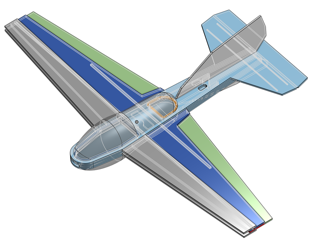
Using Onshape CAD I designed a glider very roughly based on the J-78 slope glider design by Jeff Schroeder
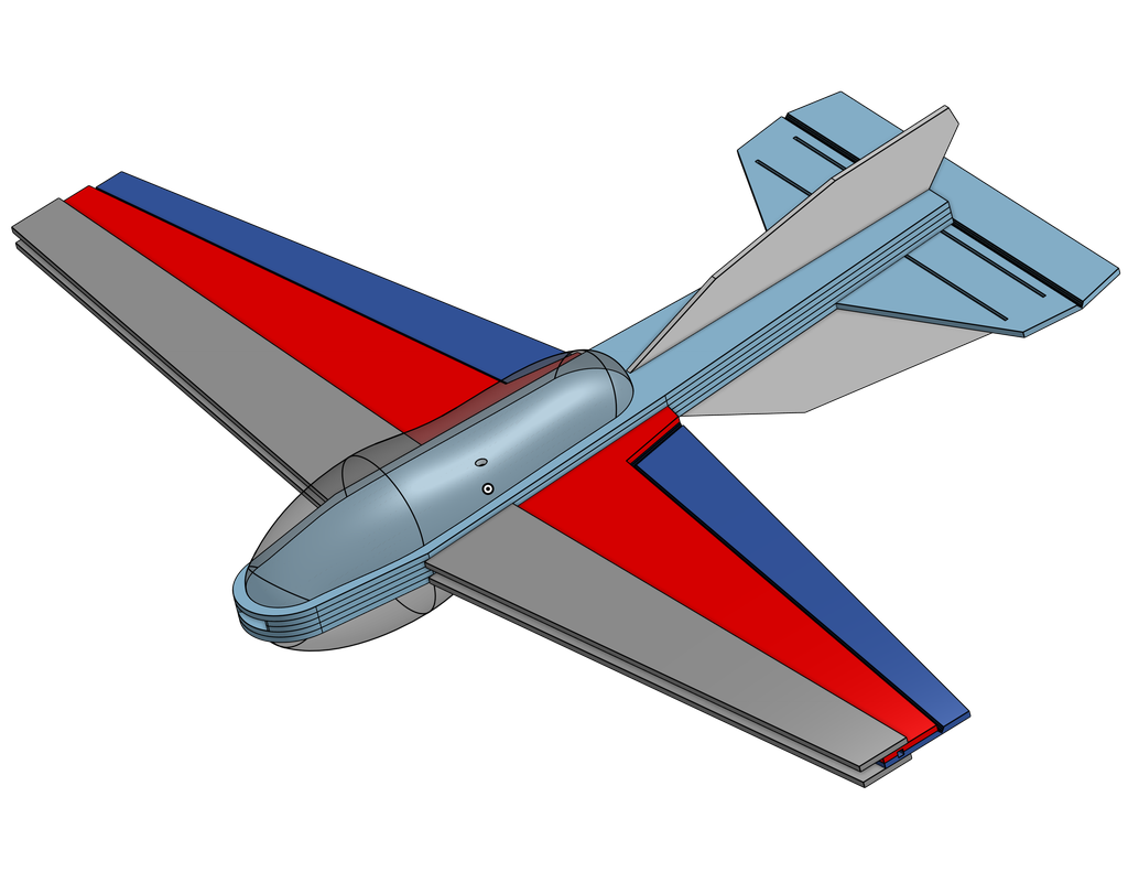
I call my design the SciGlider.
 Above: Sci Glider CAD in Onshape as of Wed Nov 9 2022. All parts will be Extruded polystyrene (XPS) foam sheet, except: canopies will be 3D Printed, and supports will be carbon fiber and aluminum tubing.
Above: Sci Glider CAD in Onshape with hidden edges shown in light gray. This shows the channels and pockets that will be milled for aluminum and carbon fiber rods. Milled slots near control surfaces, will allow taping the top edge and breaking the foam along the slot to make articulated control surfaces if the glider is to be converted to RC control.
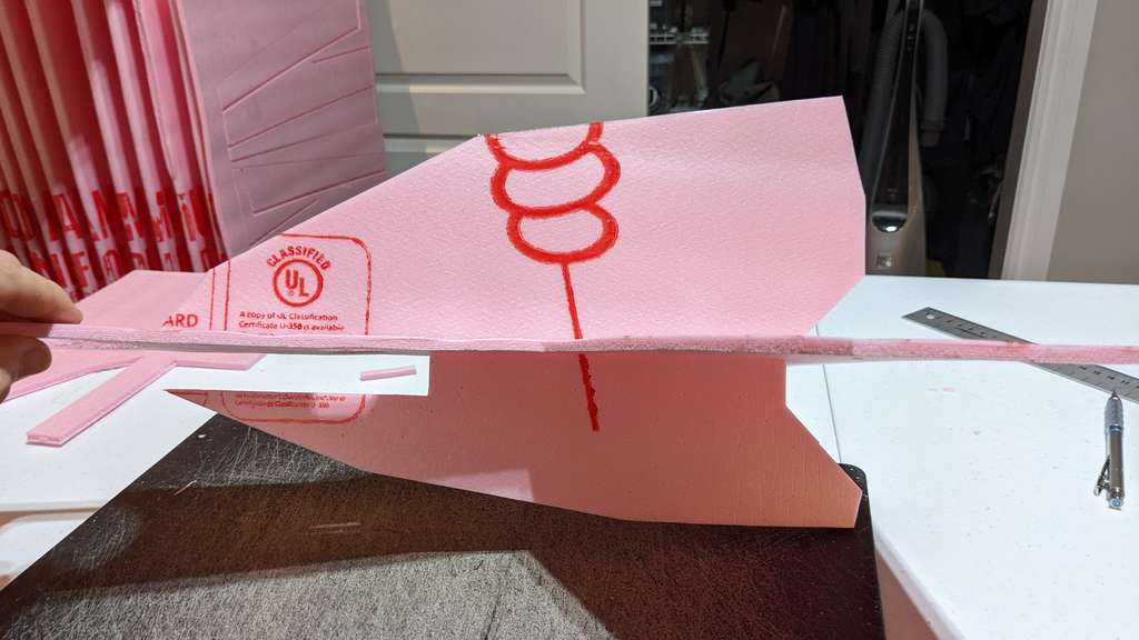
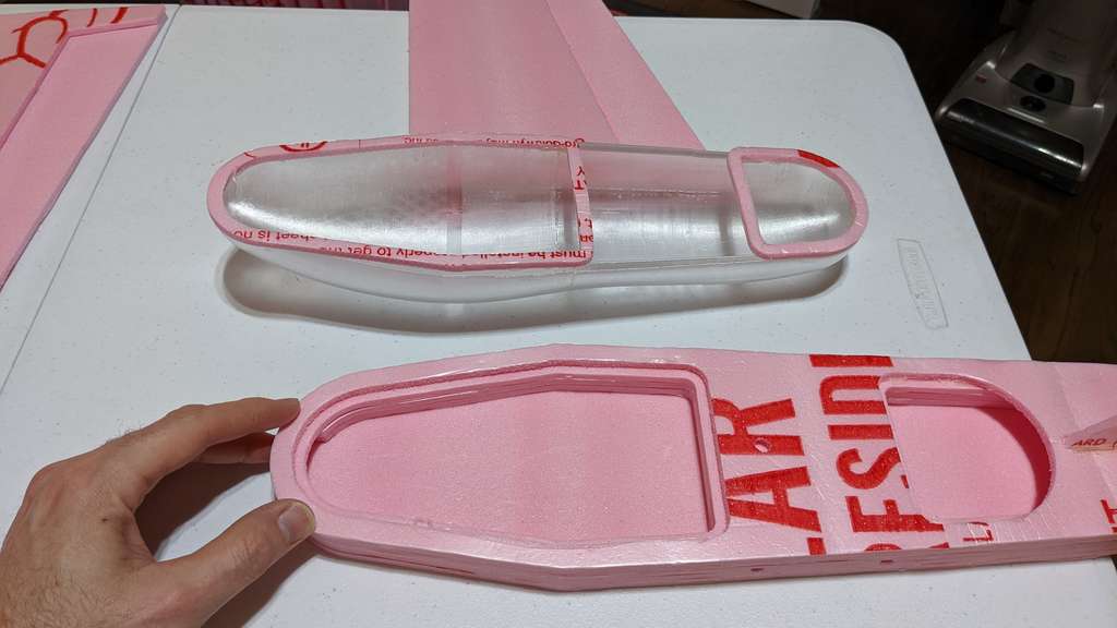
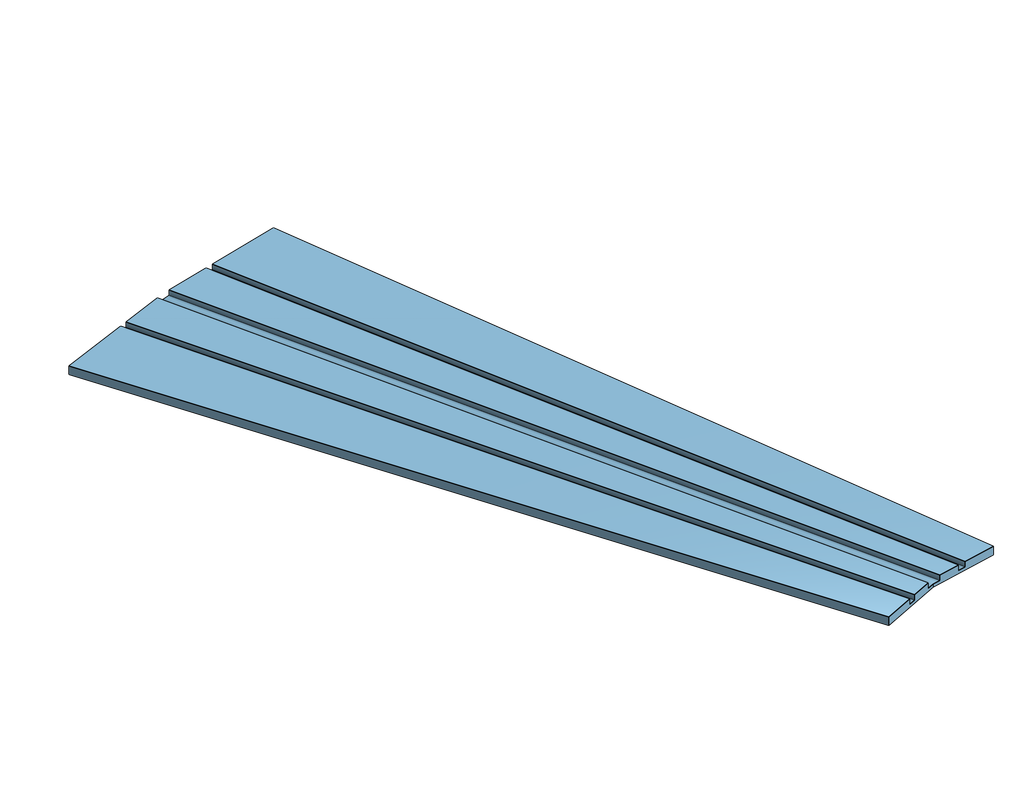 Above: KF Airfoil, wing leading edge part design. This part will be folded over the leading edge of the wing to create a KFm airfoil. See Wikipedia: Kline–Fogleman airfoil for more info. How this part works will become evident during assembly of the glider.
 Above: Bottom side of SciGlider
CAM-toolpath process


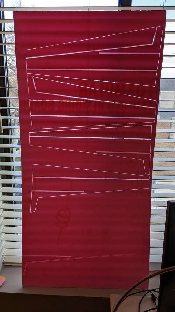
Above: Onshape layout drawings 1:1 scale. Parts are laid out on the 560 x 1100 mm sheet size of a typical XPS foam sheet with a margin subtracted to allow for some misalignment of the foam sheet when it is loaded into the Foam Crawler. Note nesting of parts to save material.
Next I use Inkscape to join all the individual line segment generated by Onshape together.
- Select all the lines
- Go Path->Combine (CTRL-K)
- Go to the Node Editor
- Select all nodes (CTRL-A)
- Click the Join Selected Nodes icon
- See it closes all the gaps in one go.
Source: Inkscape Forum: Joining separate lines into one polygon (efficient way?)


Above: SVG Layout Sheet 1,2,3 download each SVG image to use in your preferred CAM system.
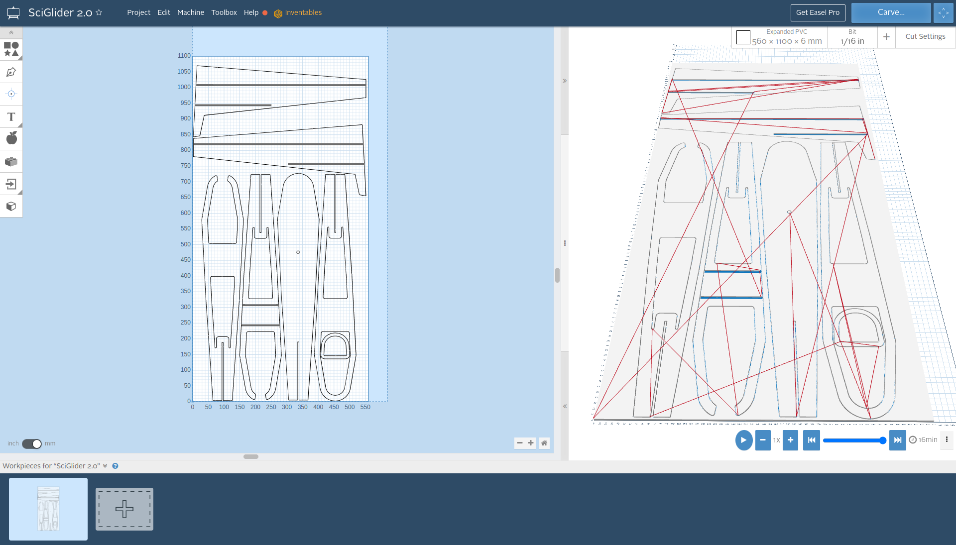
Above: tool paths for glider sheet 1

Above: settings for glider tool paths
CNC foam milling process


Above: Make sure there is enough clearance for the foam to be driven in Y in front of and behind the Foam Crawler.
Above: Wear safety glasses.
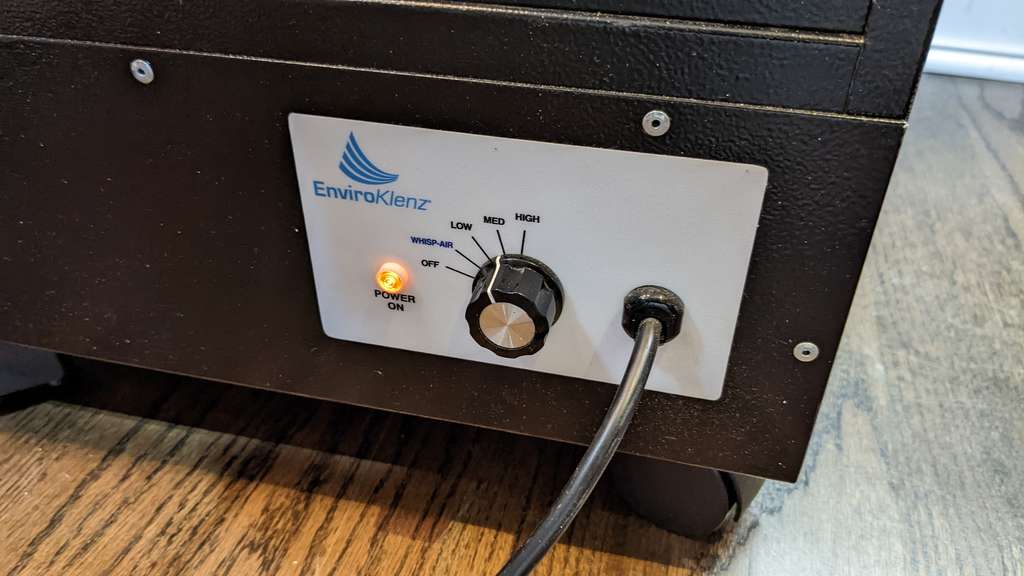
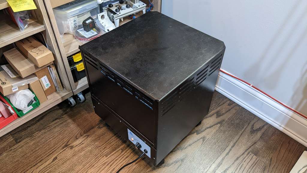
Above: Use a dust filter and fume collector.

Above: Alternatively you can use a vacuum with a HEPA filter.
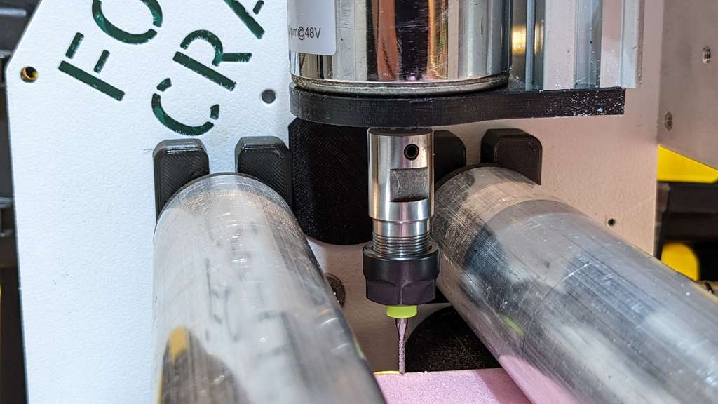
Above: Foam sheet and router bit zeroed in X,Y and Z. Touch the end mill off on the top of the foam with the end mill spinning at full speed, you should hear a small buzz of cutting when you touch the surface of the foam. Now Zero the X,Y, and Z in the FluidNC web interface.
Above: Video of real time cutting feed rate in process
Above: Video time lapse of full sheet of parts being cut.
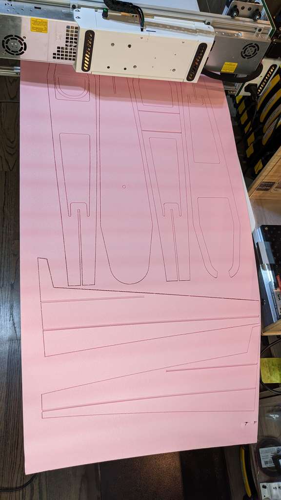
Above: Sheet 1 cut!


Above: Due to the variance in thickness of the FOAMULAR® Fanfold foam sheets Z depth is difficult to maintain properly. Note the un-cut portions of slots and pockets.
Ok! all parts for the SciGlider are cut! Now onto assembly.
Glider assembly process
Materials used for construction and assembly:
- Depron Extruded polystyrene Sheet 5.7 to 5.8 mm thick
- DOW Protection Board III extruded polystyrene foam 5.1 to 5.4 mm thick
- carbon fiber rods old arrow shaft can be used as well.
- fiber reinforced tape
- color packing tape
- clear packing tape
- BlenDerm Medical Tape
- Hot glue sticks
- Hot glue gun
I used the onhape CAD model to guide the assembly of the SciGlider. Note that the top fuselage / horizontal stabilizer plate captures the vertical stabilizer (tail fin) when glued in place, make sure to thread the vertical stabilizer in place through the fuselage / horizontal stabilizer before final gluing.

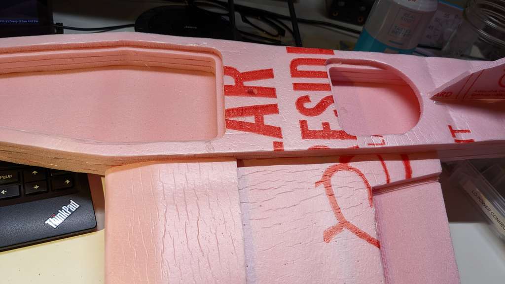
Above: Sheets of CNC cut nested parts. Parts are nested to optimize material usage. Left over foam sheet can be utilized for smaller models and projects and should be kept.

Above: Verifying measurements CAD = 227.500 mm Part = 228 mm, most likely due to parallax.

Above: An additional 40mm was added to the slot on the fuse and horizontal stabilizer part to accept the vertical stabilizer (tail fin). The most recent CAD file has 50mm added to this same slot to make the assembly even easier.
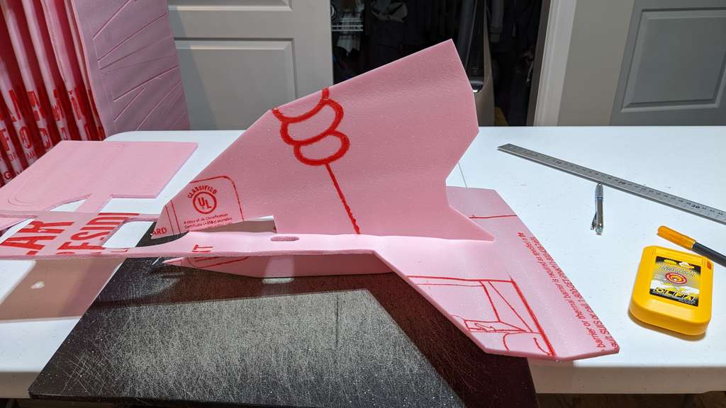
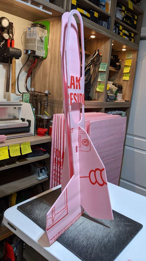
Above: the vertical stabilizer (tail fin) must be inserted into the top sheet of the fuse first.
Above: Vertical stabilizer (tail fin) fully seated in the top sheet of the fuse.
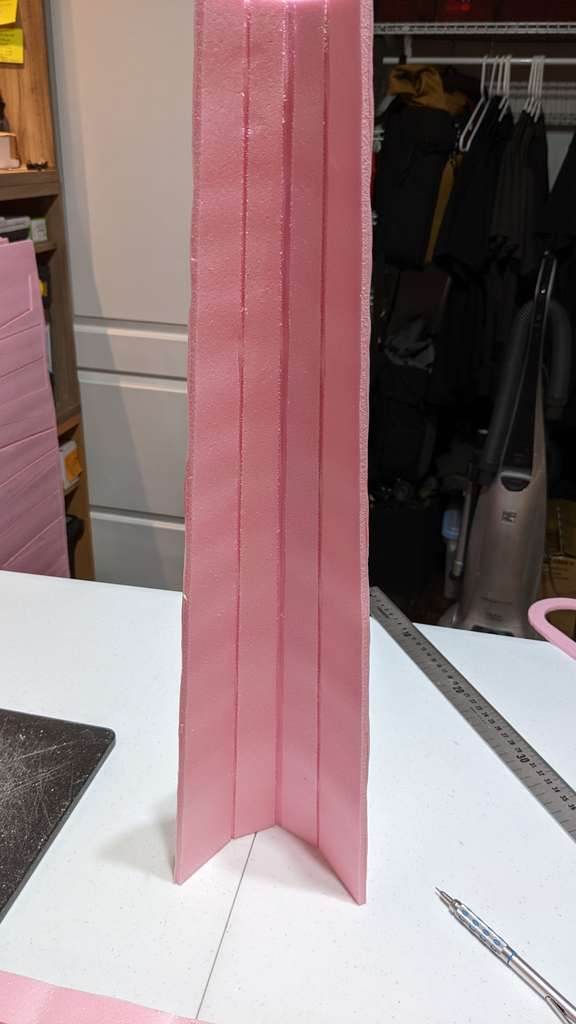
Above: Pre-Bending KF Airfoil, this part will be glues with the leading edge of the wing sandwiched into the C shape of the KF airfoil.
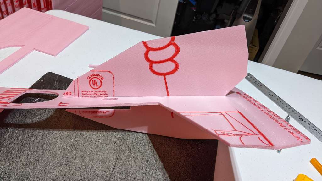
Above: the lower sheet of the fuselage slips into place onto the Vertical Stabilizer (Tail Fin)

Above: Dry fit all parts before gluing. This will help you understand where glue must be used and where it should not be used. This also verifies that there was no skip steps or slippage of the sheet foam during milling.

Above: Dry fit the 3D printed canopy in place on top of the slim foam canopy locator parts.
Above: Avoid getting glue on the seams between the thin foam canopy locators. Use a small amount of glue so you can pull the canopy off the fuselage along with the faom locators. Then you can add more glue from the interior of the canopy assembly.

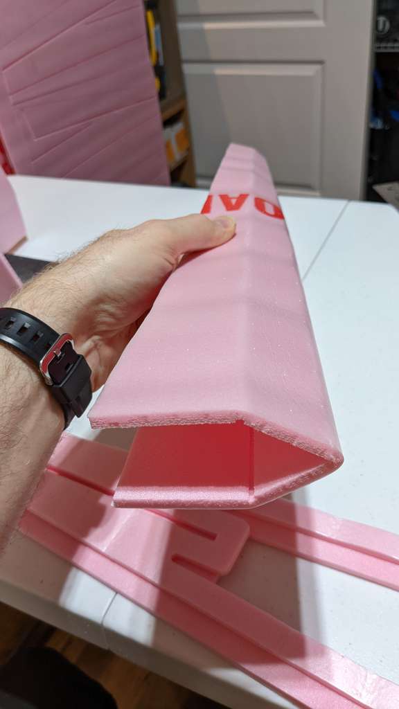
Above: This is what the KF airfoil part should look like after gluing on the leading edge of a wing half. Glue the bottom part first and wait for it to completel dry before moving to the top part for final assembly. Slide the second part around while the glue is still liquid to position the KF foil in a way that there is minimal twist when looking at the wing straight on from the front edge.

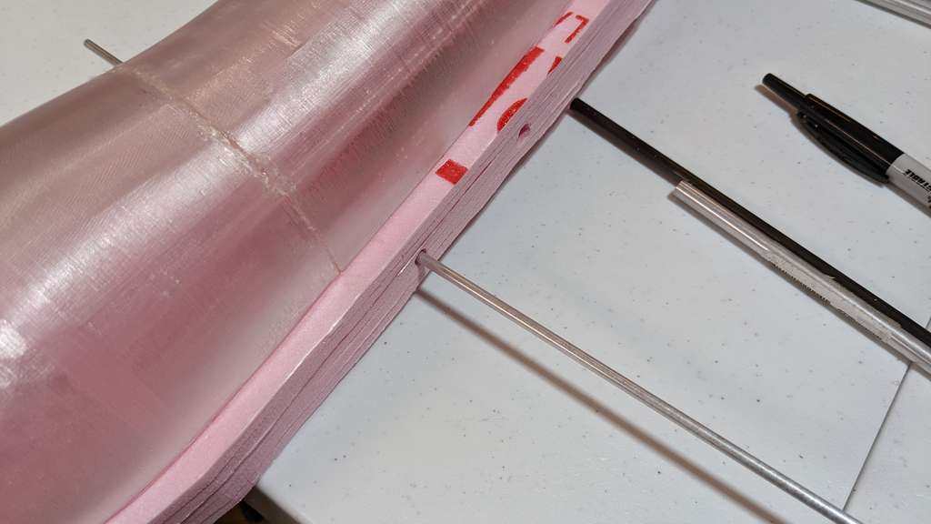
Above: Dry fit a 6mm cabon fiber tube through the two holes in the fuselage.

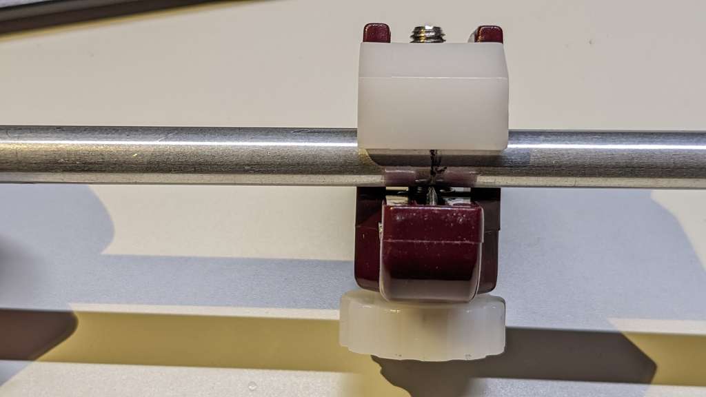
Above: Dry fit a the 7mm aluminum tube over the 6mm carbon fiber tube through the two holes in the fuselage.

Mark the Aluminum tubes along the fuselage edge.
Above: If the holes get glue in them or are too tight, don’t worry just use progressivly bigger diameter aluminum tubes to core drill out the holes.

Above: A smaller tube can serve as a guide for the next bigger aluminum tube core drill

Above: Aluminum tube core drill removing some foam from a hole.
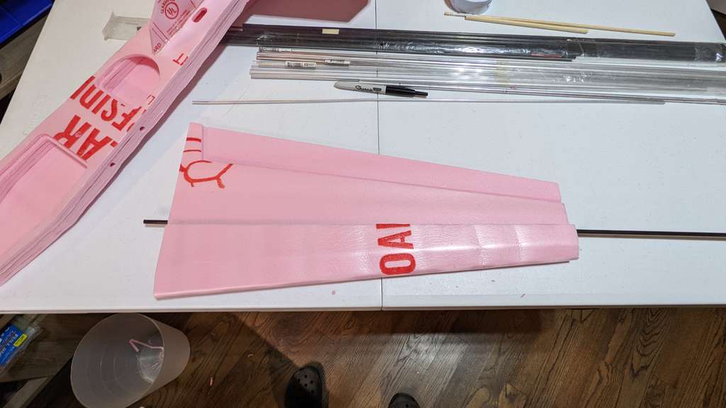
Above: Insert the 6mm carbon fiber tube into a finished wing half. An interference (snug) fit is ideal, since it will hold the wing during flight. If the fit is not tight enough experiment with adding cellophane and or clear tape to the carbon fiber tube to create a snug fit.

Above: Short aft carbon fiber rod and forward longer carbon fiber tubes installed in a wing half. We will now line the tube sockets in the fuselage to the left with aluminum tubes to increase strength and durability. These aluminum liners will also allow repeated disassembly of the glider for easier transport in small vehicles, by backpack etc.
Above: Cutting aluminum tube lined socket holes in the fuselage to the left.
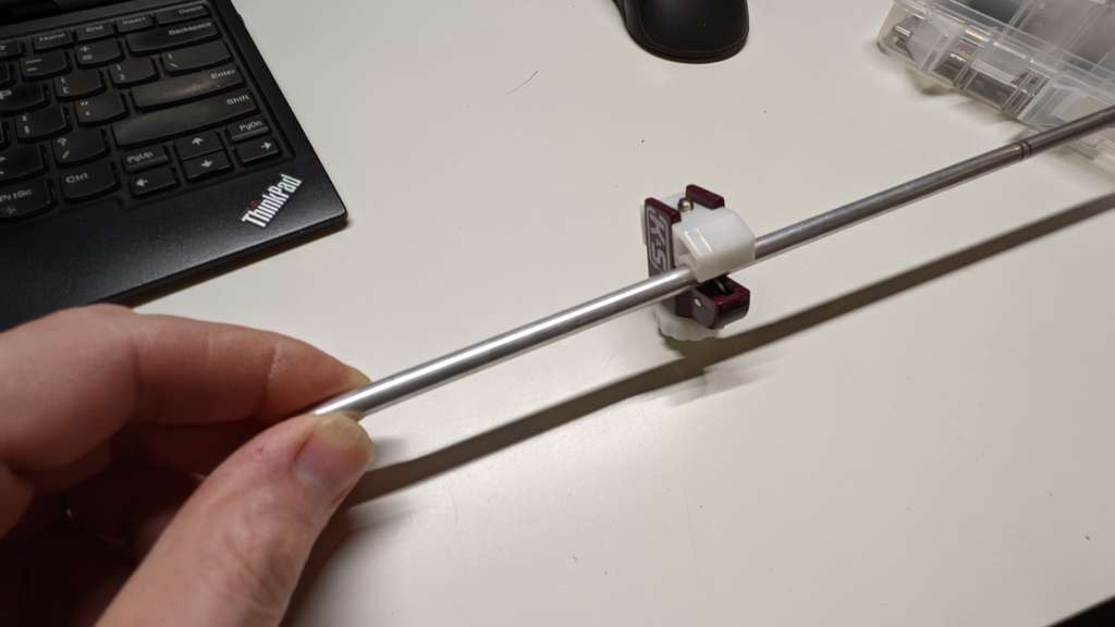
Above cutting the aluminum tube with an K&S tubing cutter.
 Above: Chamfering interior edges of the aluminum tube.

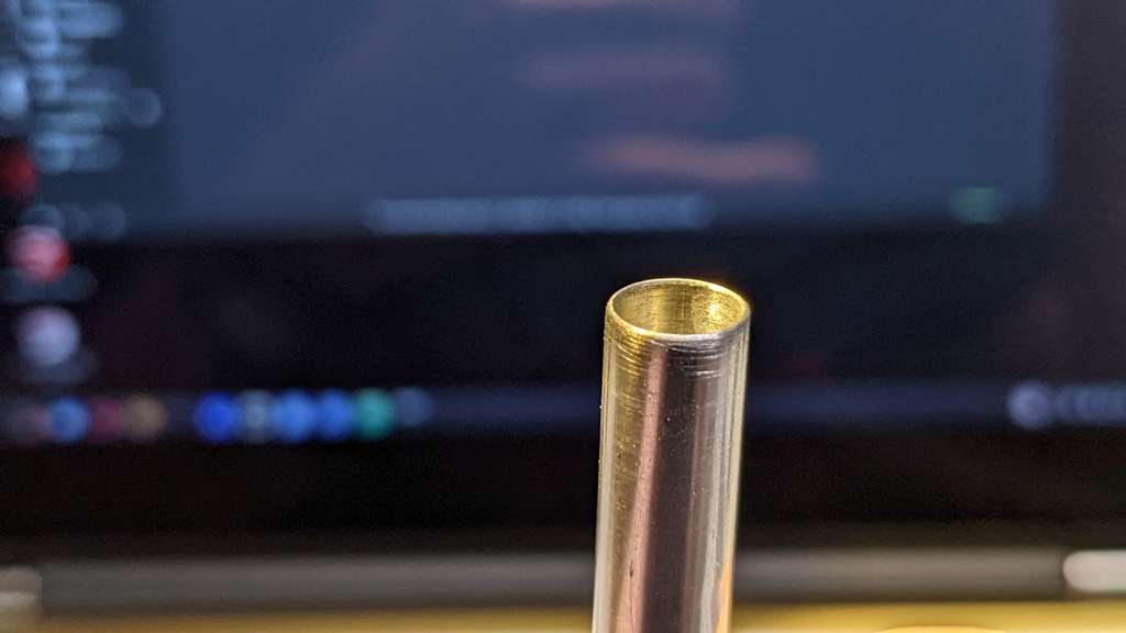
Above: Sanded interior edges of the aluminum tube will prevent scoring of the 6mm carbon fiber tube that will travel through.

Above: Wing assembly approaching the fuselage with a friction (slight interference) fit.
 Above: Wing seated
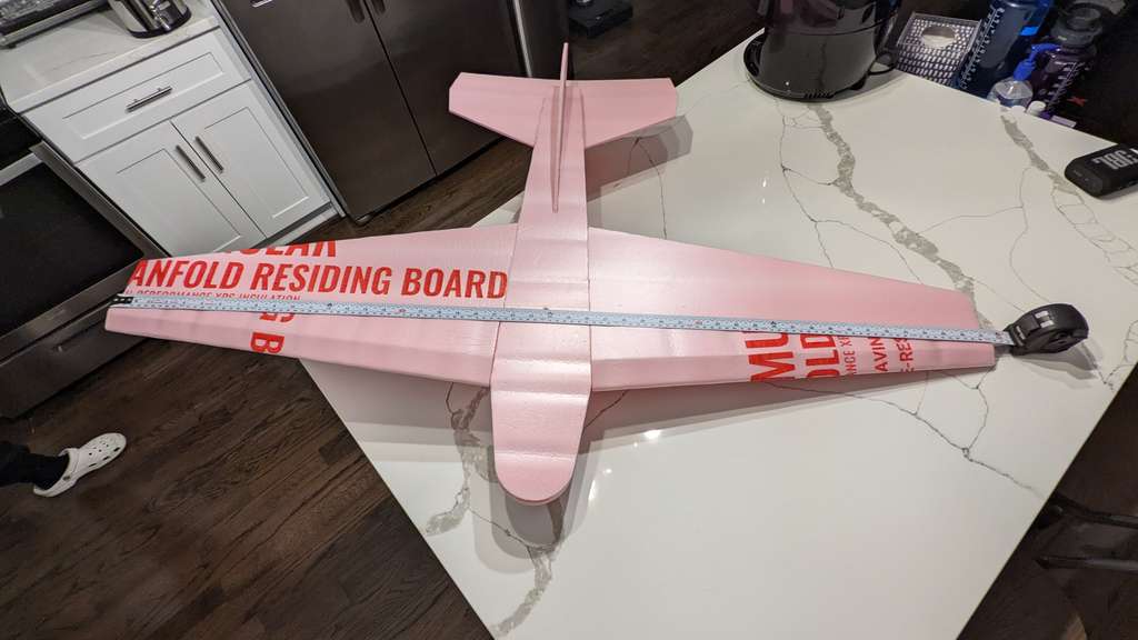
Above: measuring 1.2 meter wing span.

Above: 1.2 meter wing span as measured close up.
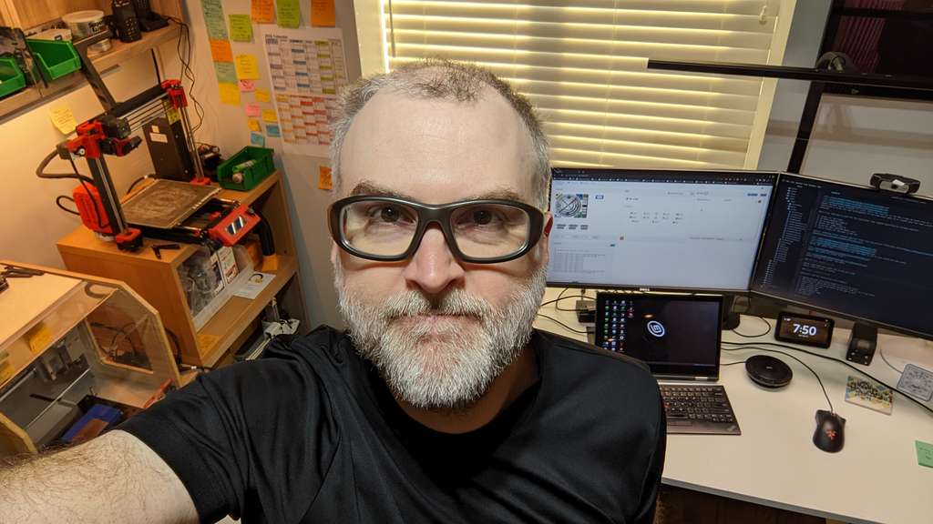
Hero Shots

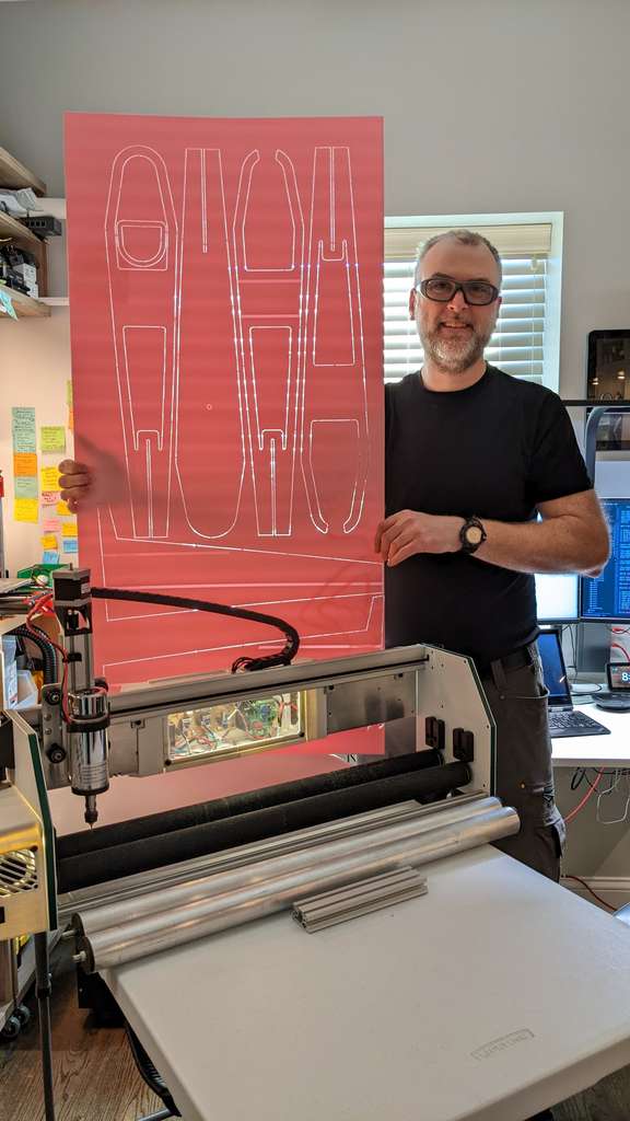
Here I am with the completed SciGlider The wingspan is 1.2 meters! This is the largest foam aircraft I have ever built! I can’t wait to test glide the SciGlider and possibly add radio controls.
Design Files
In case the link above does not work in the distant future:
SciGlider Parasolid Assembly File
SciGlider Parasolid KF Airfoil File
SciGlider G-Code for your Foam Crawler:
SciGlider01.nc Sheet 1 parts
SciGlider02.nc Sheet 2 parts
SciGlider03.nc Sheet 3 parts
All SVG files used for CAM toolpath generation are above as images in the CAM section. Simply right click and save the SVG file to your local computer.
Reflect on what you learned
Foam properties
Foam is difficult to measure with a calipers to high precision. Waves in low cost foam sheet does impact Z axis pocket depth consistency. Depron foam is much flatter and therefore a better choice when blind pockets are needed at a specific depth.
Slot and Tab Construction
Slot and groove construction allows for very strong interlock and location for model aircraft construction. Foam has some give when used for tab and slot construction, designing slots to the exact thickness of the material results in a snug interlock. Deep slots have the capability of aligning sheet stock parts perpendicular to each other without the aid of a square during construction. This makes assembling the vertical stabilizer of model air craft properly a much easier task than traditional butt joints.
Accuracy
The Foam Crawler may be able to obtain +- 0.07mm accuracy due to run out. This is more than enough accuracy for model aircraft, patterns for routing furniture, and making foam patterns for sand casting.
Speeds and feeds
The SciGlider was cut with the following Speeds and feeds: Tooling: PreciseBits 1.6mm diameter fish-tail, diamond-cut router bit spun at: 12,000 RPM with a 48VDC 400Watt DC Spindle contact me if you need a spindle like this I have over 10 of them in stock. Feed rate X & Y: 2400mm/min Plunge rate Z: 1200 mm/min Depth per pass: 7mm (single pass) Spindle RPM 6000 and 12000
I found that speeds and feeds above 3000mm/min in X and Y will start to skew the foam sheets out from between the roller drives of the Foam Crawler. I find keeping the feed at or below 2400mm/min allows for good repeatability and accuracy even when there is quite a bit of foam dust present.
I may modify the Foam Crawler with some kind of rack drive in the future and then I’ll be able to increase feeds and speeds to reduce production times.
Speed and complexity
The Foam Crawler CNC allows for a design using CAD to be transferred to CAM and cut with a high degree of precision.
Accessibility and cost
The cost of the [Foam Crawler](https://fabacademy.org/2020/labs/incitefocus/students/daniel-meyer/assignments/Week20/) is ~$500, which is quite accessible for home, garage, or community shop use, compared to other CNC mills with a similar working envelope. However the Foam Crawler is a DIY machine with a BOM that needs to be sourced by the builder and requires access to a 3D printer, a small milling machine, and some specialized tools. A local Fab Lab, or Hacker Space can provide those tools. Or a person could build their own Fab Shop (Mini Fab Lab) and then make the Foam Crawler.
Link to group assignment
2022 References
A primer on speeds and feeds can be viewed on Wikipedia:Speeds and feeds
2020 Assignment
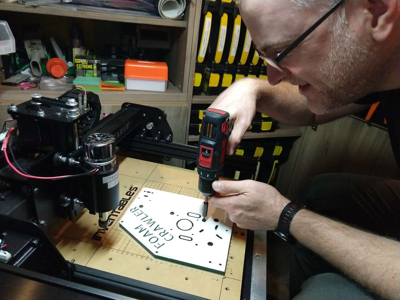
HDPE Side Plates
I decided for this assignment to mill the side plates of my Foam Crawler machine from two color 12 mm thick HDPE. Each machined plate is 200 x 250 mm. These two side plates connect to long aluminum extrusions to make a machine frame that holds all mechatronics required to run the machine.
Size
The overall assembled machine size will be quite large:
| Dimension | SI | Inches | Feet |
|---|---|---|---|
| Length | 0.80 m | 31.5” | 2.6’ |
| Height | 0.44 m | 17.3” | 1.4’ |
| Depth | 0.27 m | 10.6” | 0.9’ |
CAD
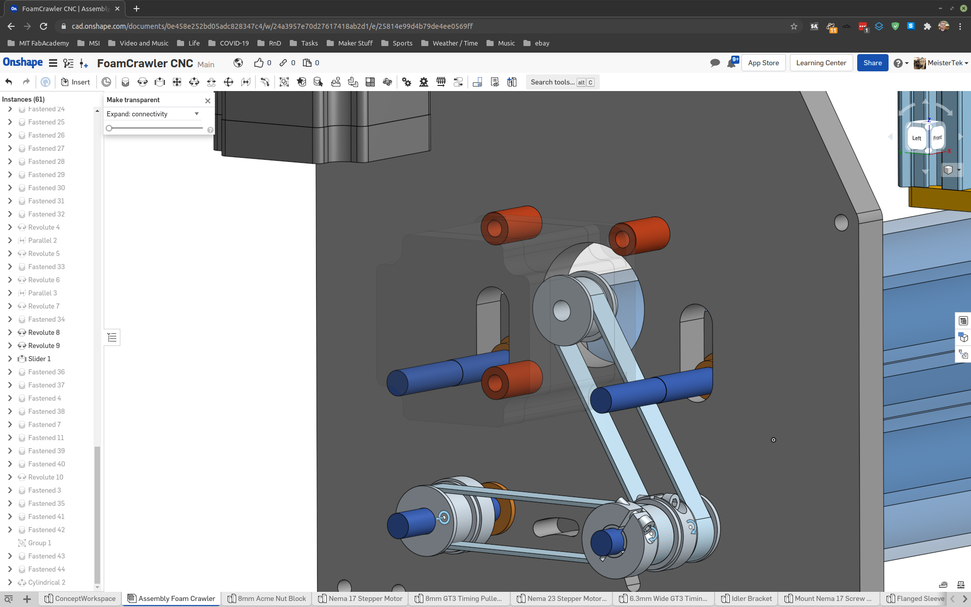
 Stage 1 of of virtually assembling the machine. I will make design changes during this virtual assembly to make the machine perform better and make building and maintaining the machine easier.
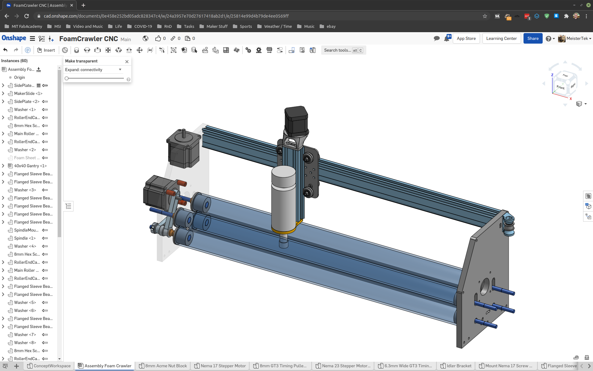
Yesterday and last night I got a lot of work done. Here is my assembly model as of Sunday 3:30 AM
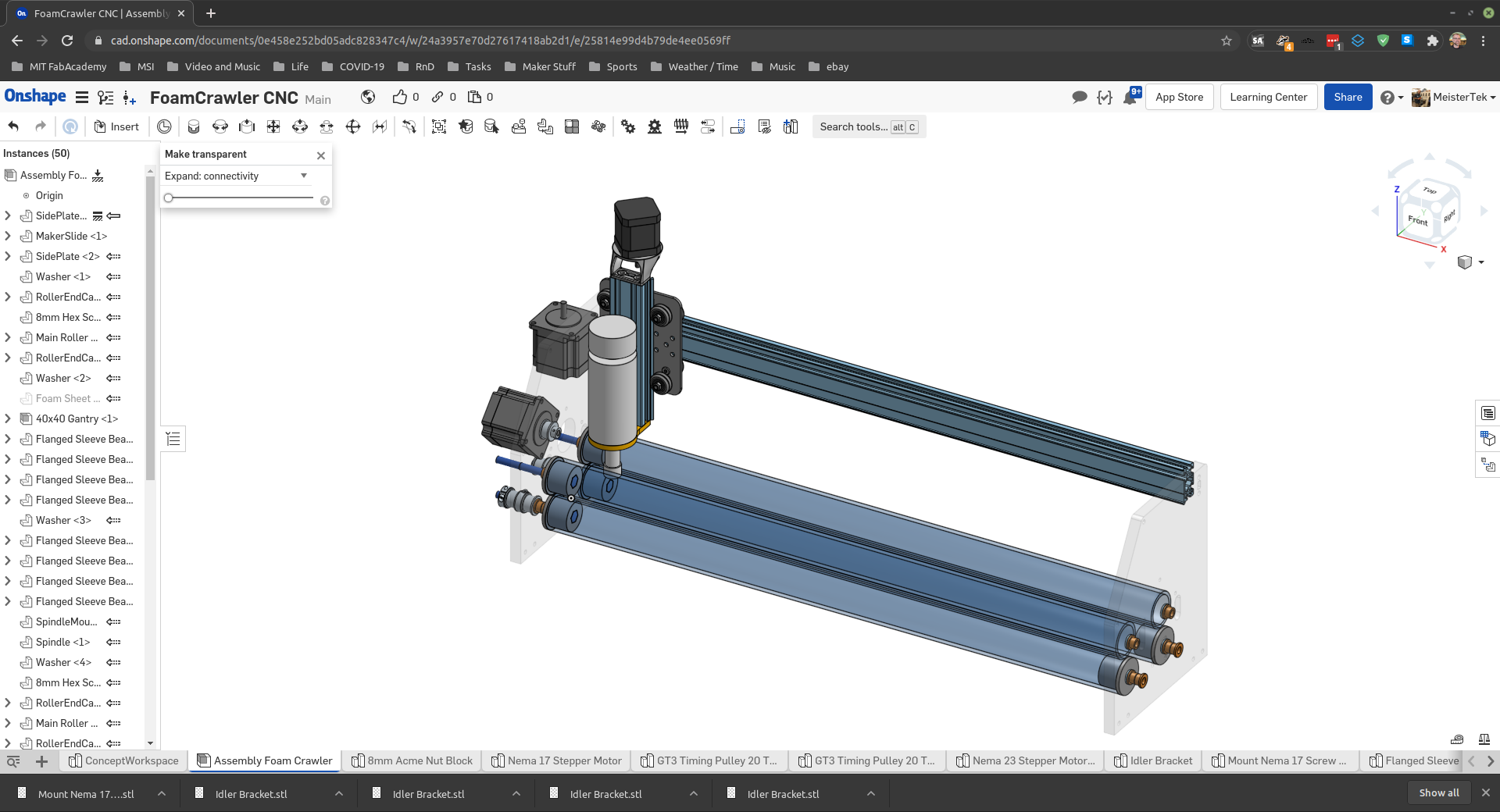
It’s been some time since I have done virtual assembly using CAD and,,, boy is it fracking powerful. This is the first time I have explored the assembly mates that Onshape uses. They work really well once you understand them. Onshape has excellent documentation.
At this point in time I have over 60 parametric assembly mates, and a BOM of 29 unique parts and a total parts count of 118.
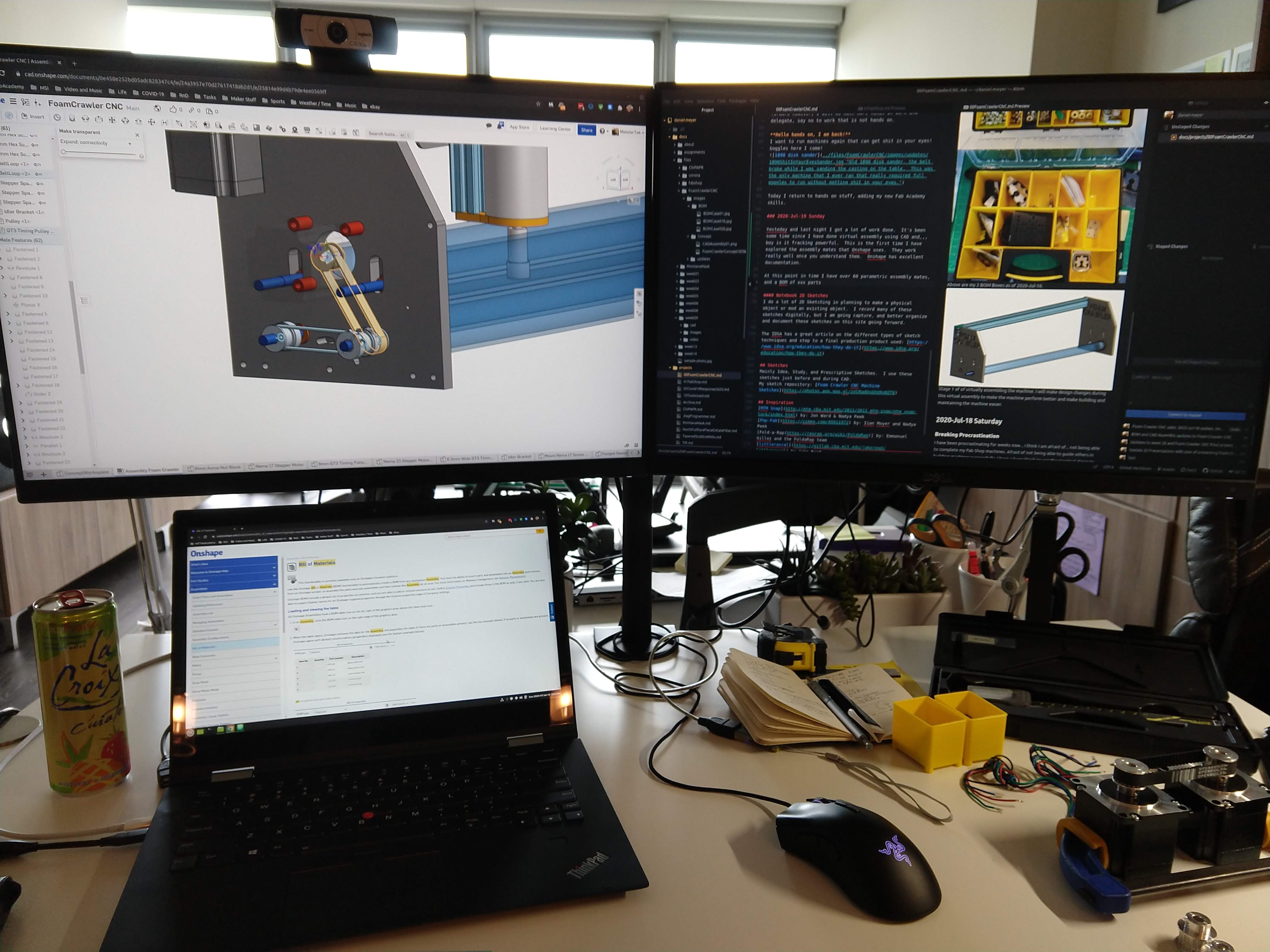
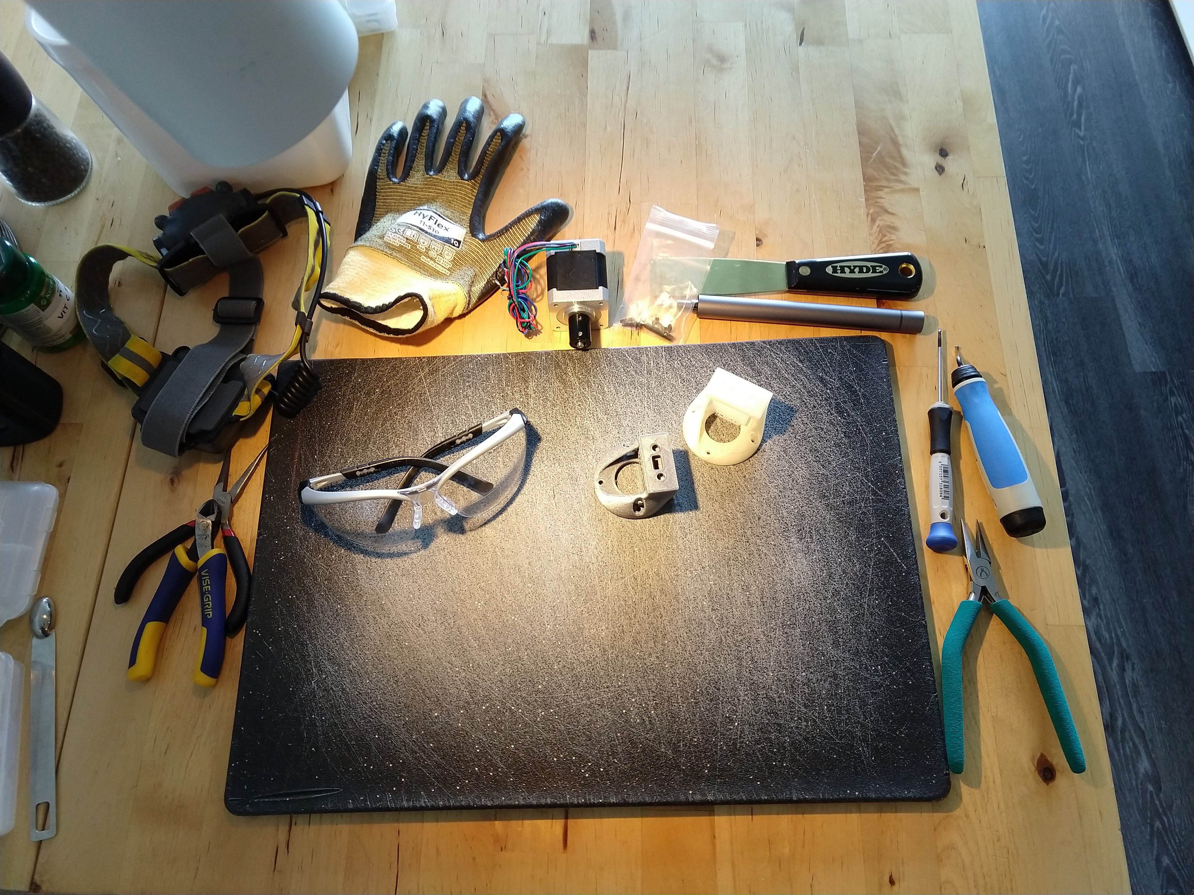
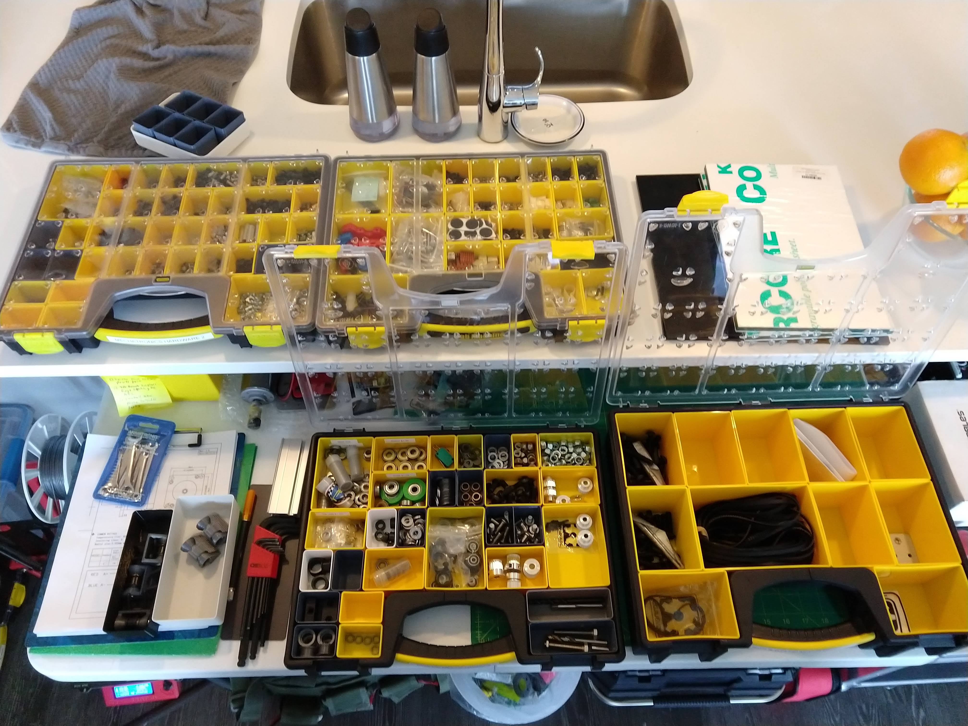
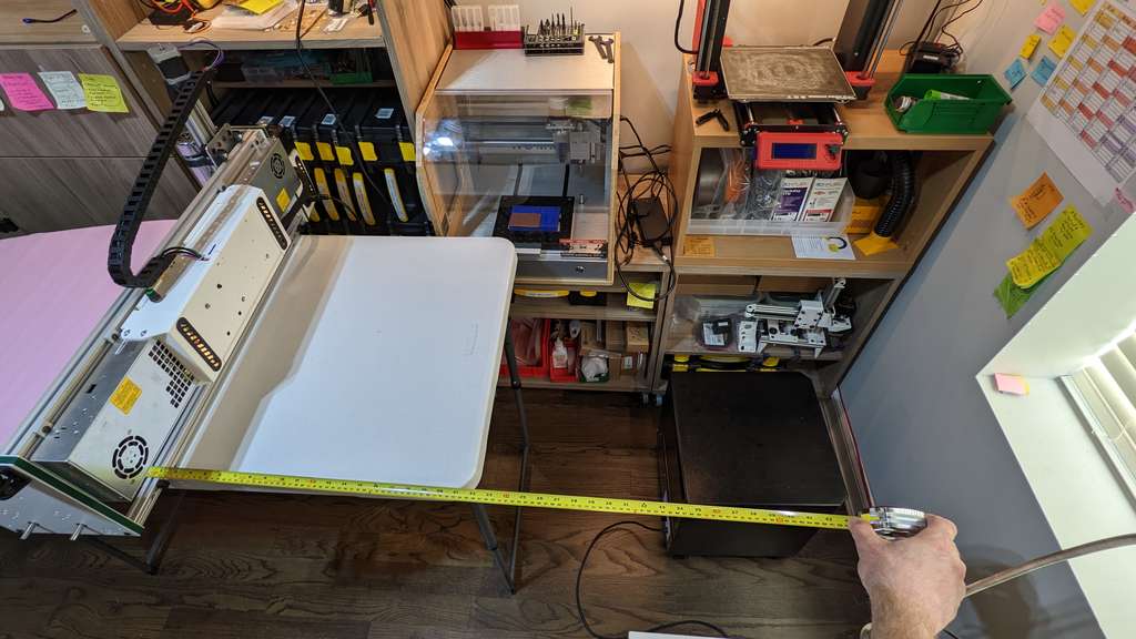
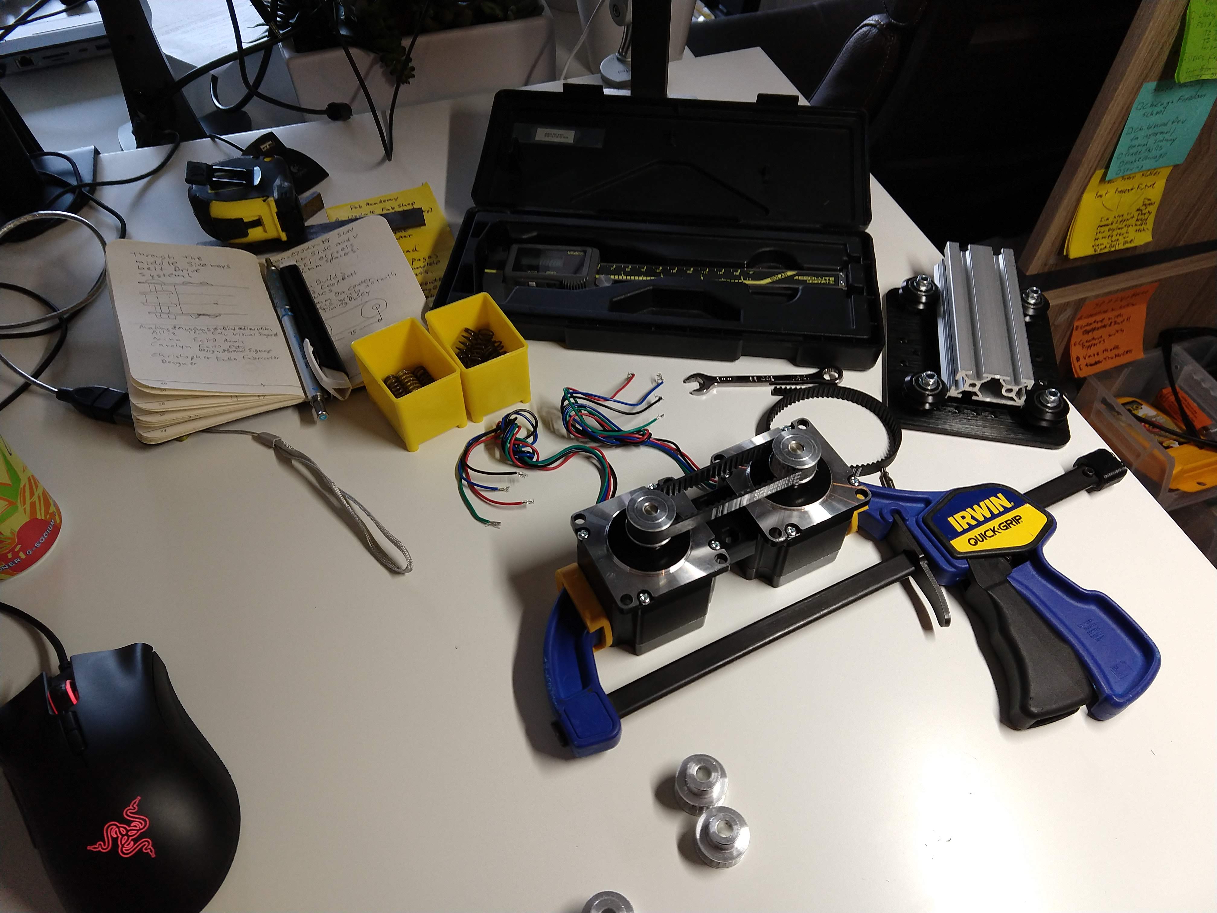 Above are some shots of my workspace as I design, 3D print, test and assemble in real and virtual worlds.
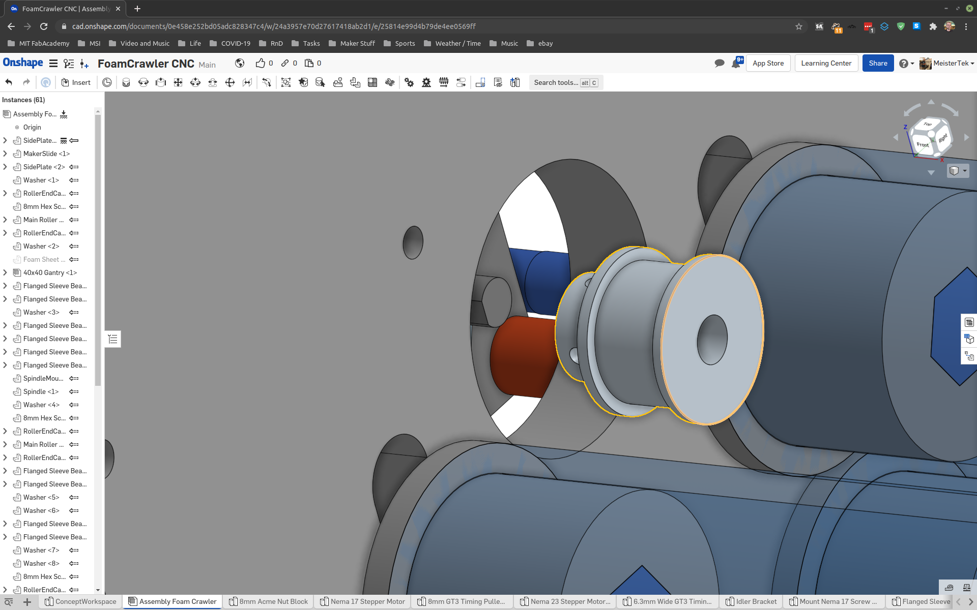
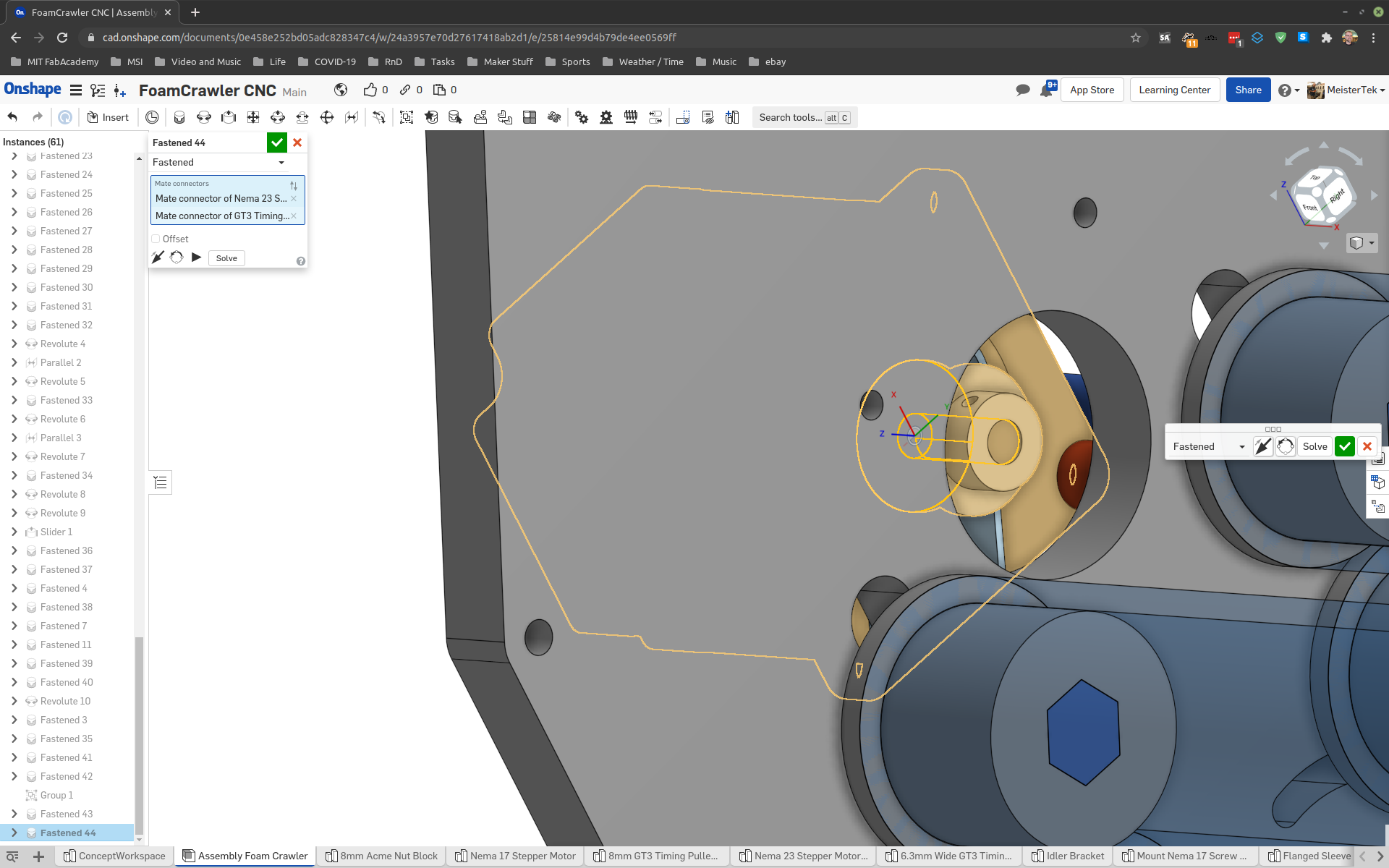
More screen captures of virtual assembly:

X Y Z CAD Check
Time for final checks of X, Y, Z ranges in parametric CAD. Double check drive system geometry.
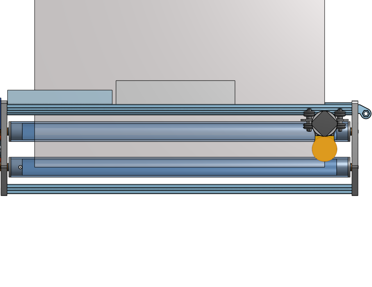
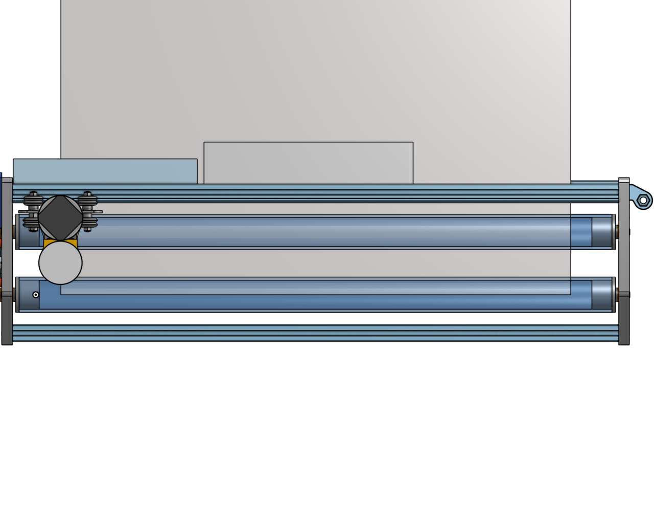


All looks as good as it’s going to get!
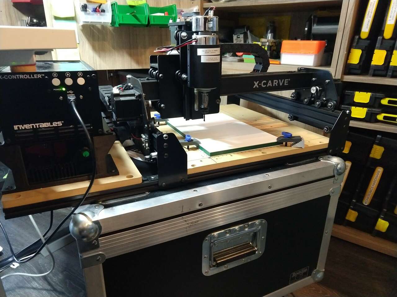
Time to mill the HDPE side plates on the 250x250mm X-Carve I have here at home. I have 3D printed all the parts needed. I went to Home Depot and purchased PVC pipe and fasteners that haven’t arrived from McMaster yet, PVC pipe is much cheaper than from McMaster anyway.
Milling and Machine Parameters
| Feedrate | Speed | Plunge Rate | Cut Depth | Tool | TIR |
|---|---|---|---|---|---|
| 381 mm/min | 12000rpm | 228 mm/min | 1 mm | 3.175 mm Single Flute Upcut End Mill | 0.04 mm (.0015 in) |
See my project on Total Indicated Runout (TIR) for more information on how I set end mills in the X-Carve mill.
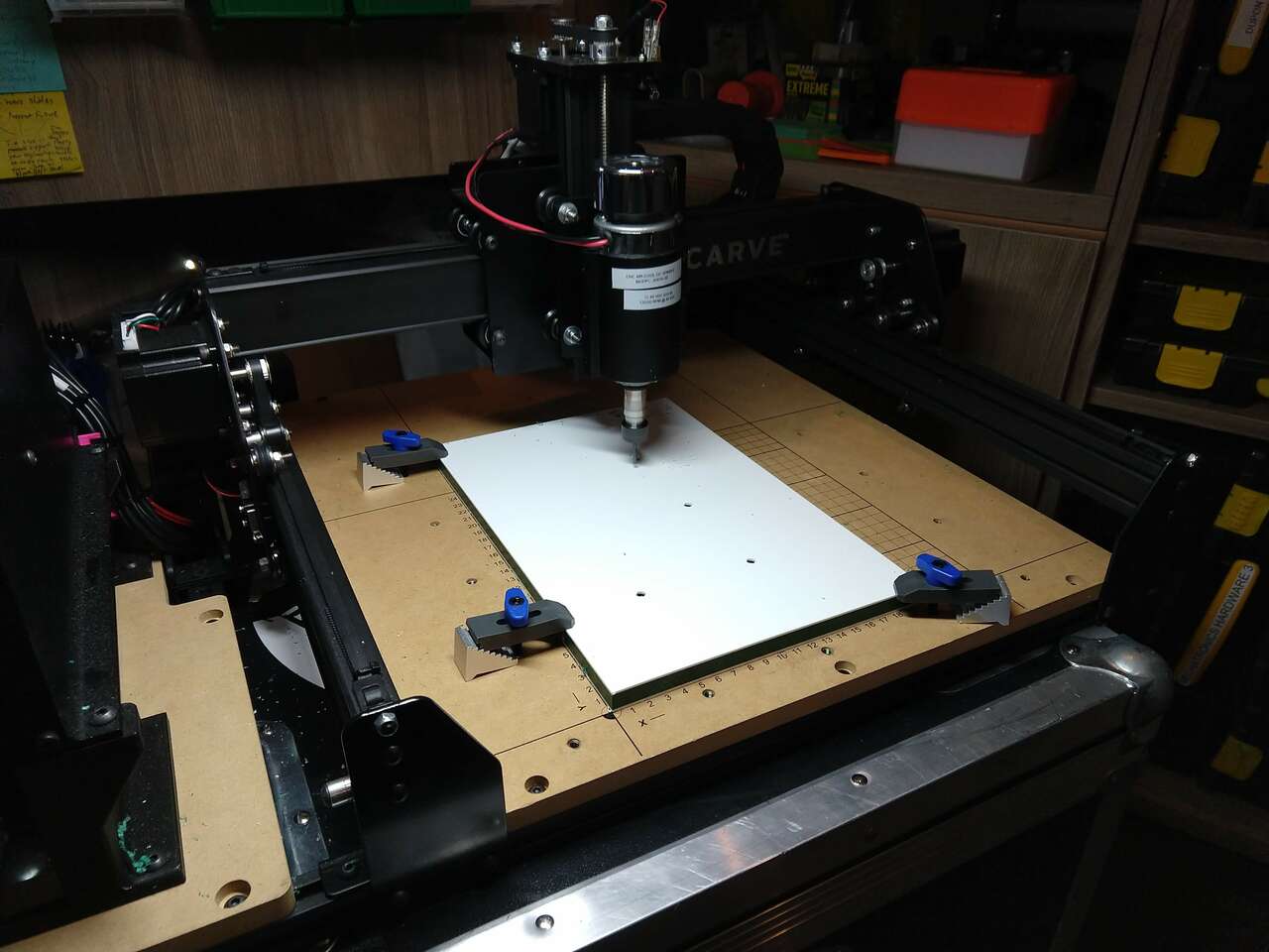
 HDPE sheet clamped in place with Inventables Step Clamps.
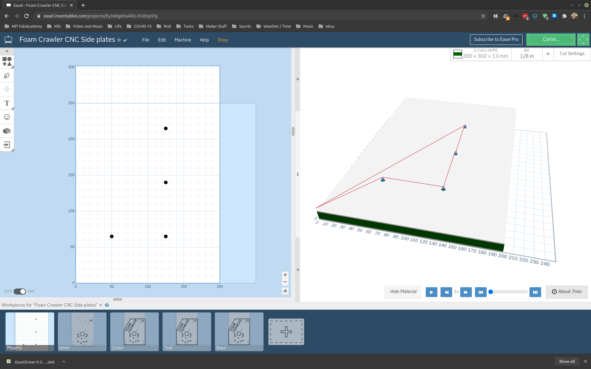 Hold down tool path
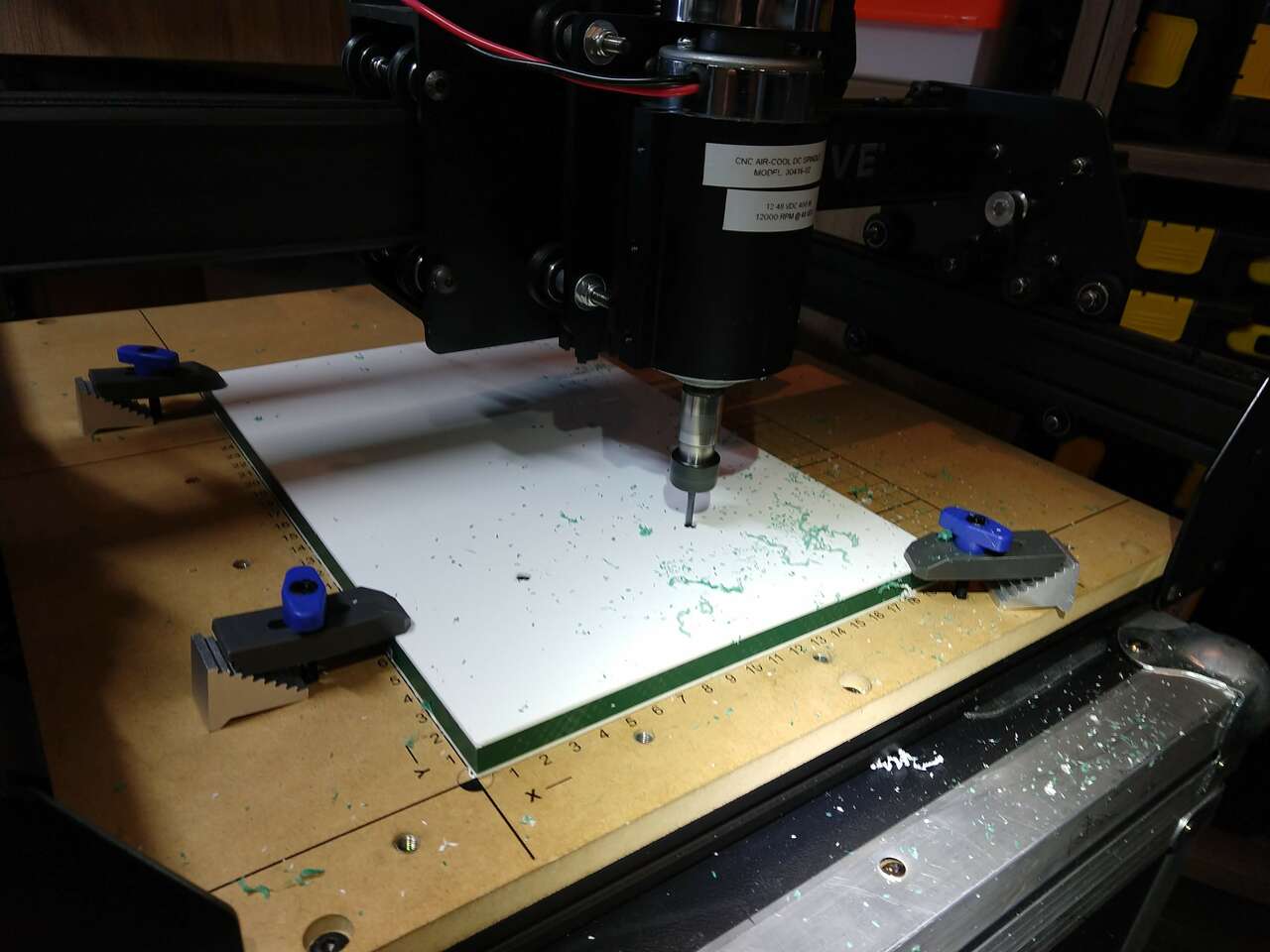 Hold down milling
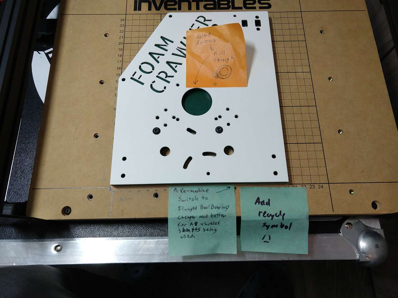
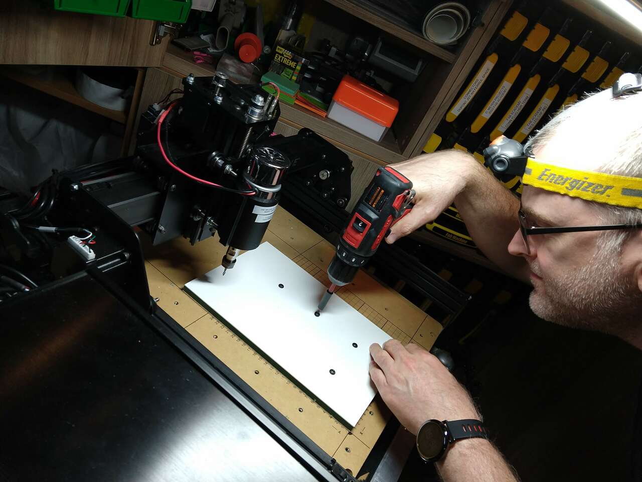 Step clamps removed, hold down screws added
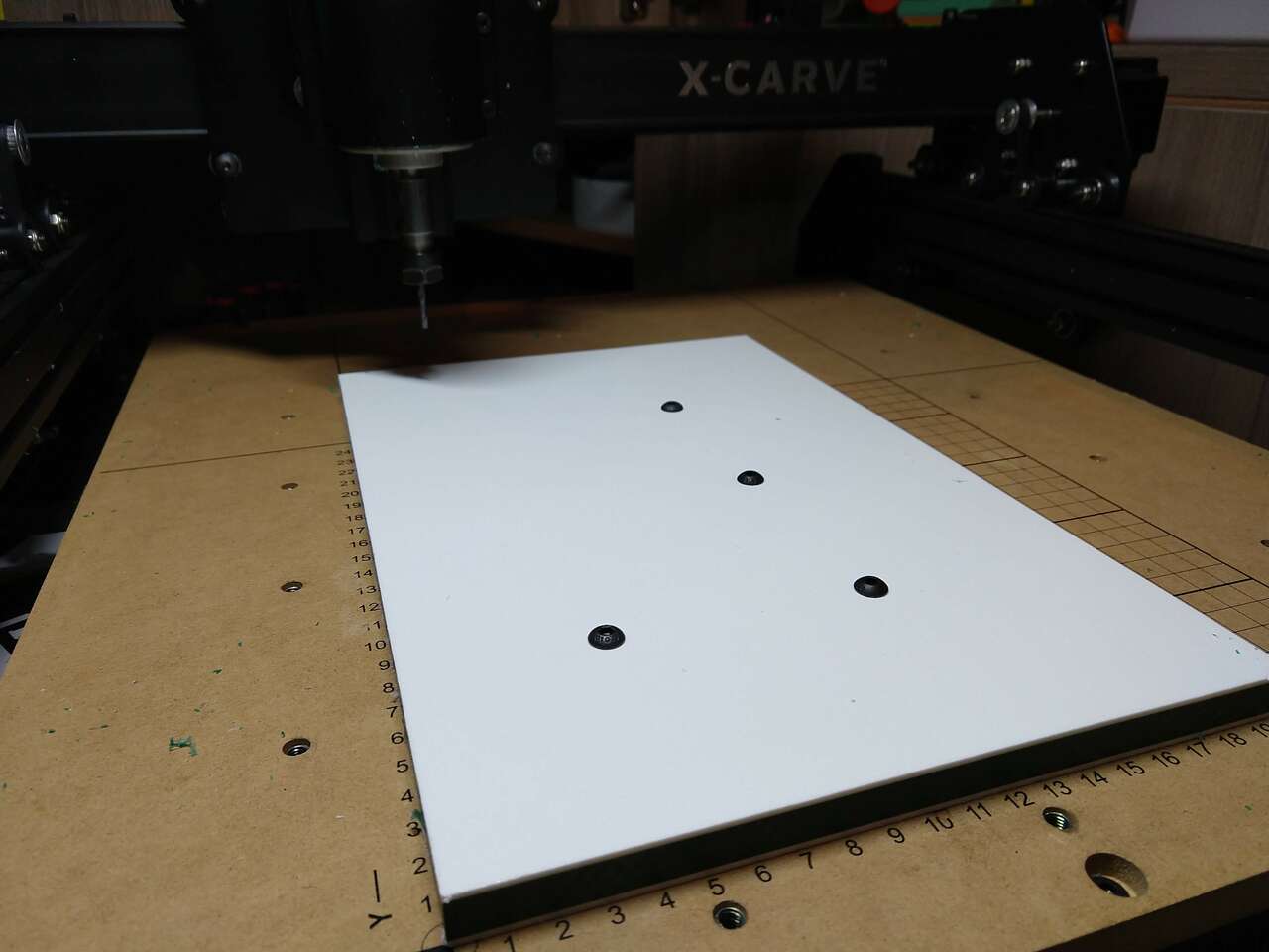 Hold down screws fulling installed. These hold down screws have a slip fit into the HDPE holes. This allows for alignment of the part to be held during milling. Also the HDPE part can be removed and remounted onto the machine bed multiple times to add machining later. These hold downs can also accommodate flipping and locating the part for second side machining with alignment retained.
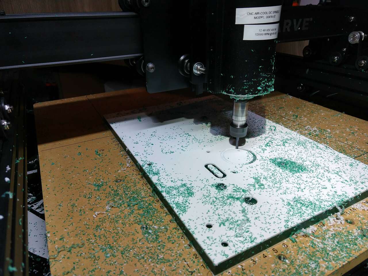
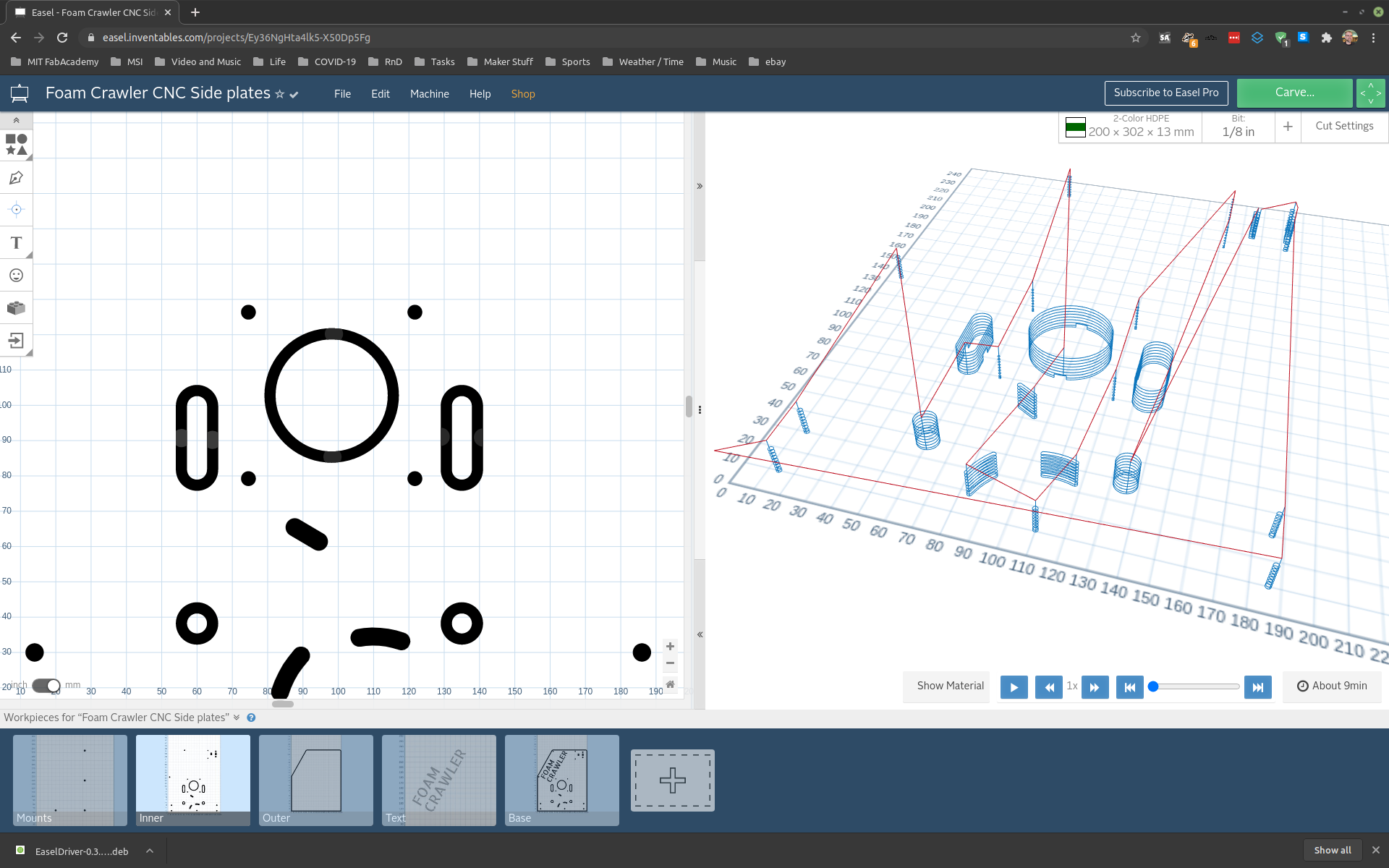 Inner Milling
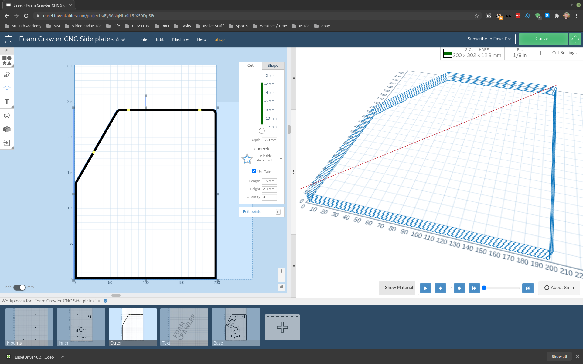
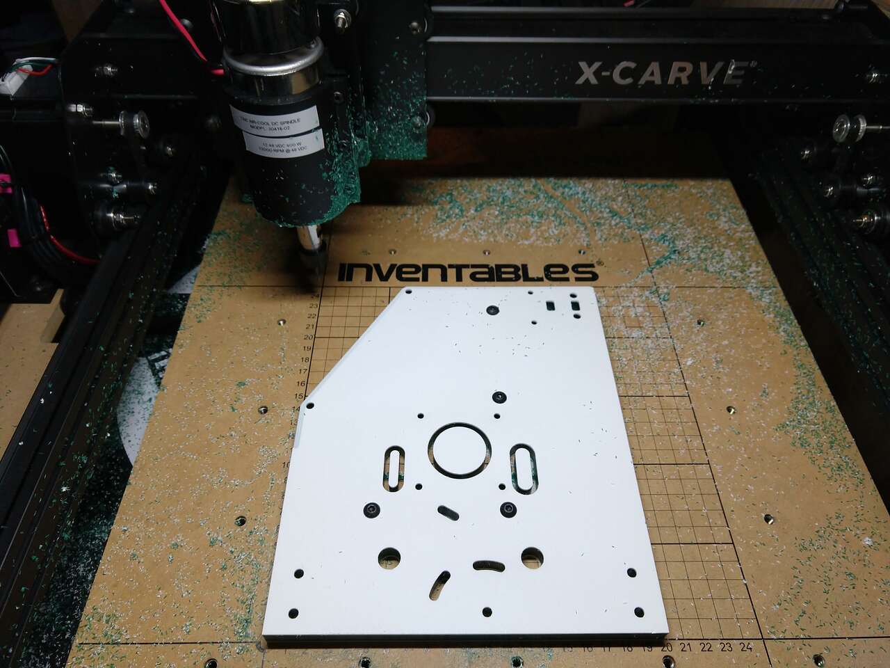
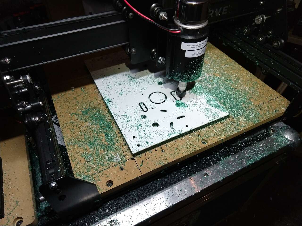 Outer Profile Milling
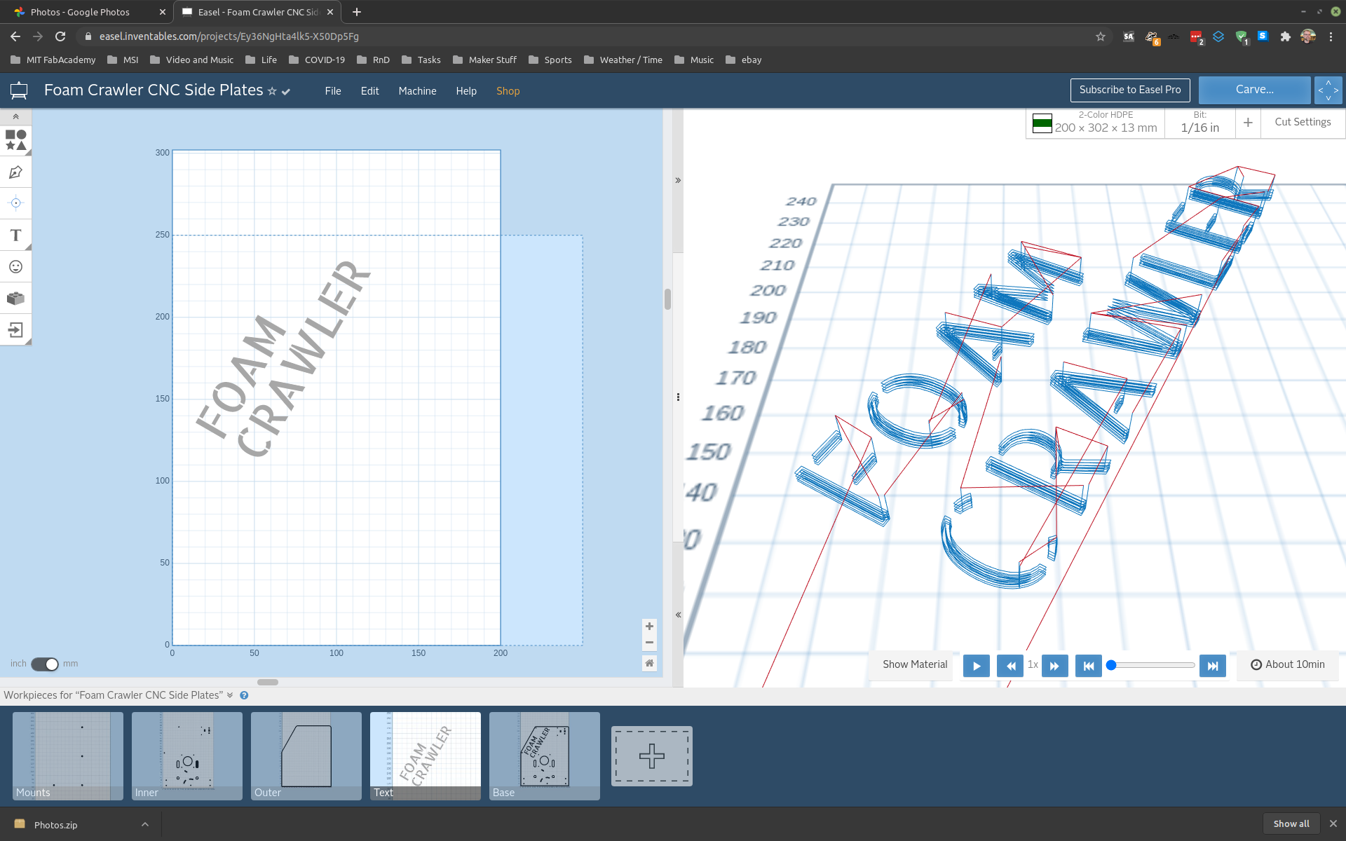
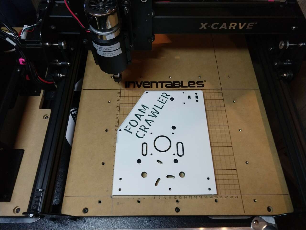
 Text Milling
| Feedrate | Speed | Plunge Rate | Cut Depth | Tool | TIR |
|---|---|---|---|---|---|
| 381 mm/min | 12000rpm | 228 mm/min | 1 mm | 1.6 mm Fishtail Spiral, Upcut Bit | 0.04 mm (.0015 in) |
 Removing hold downs
Assemble Machine
 Corrections and updates
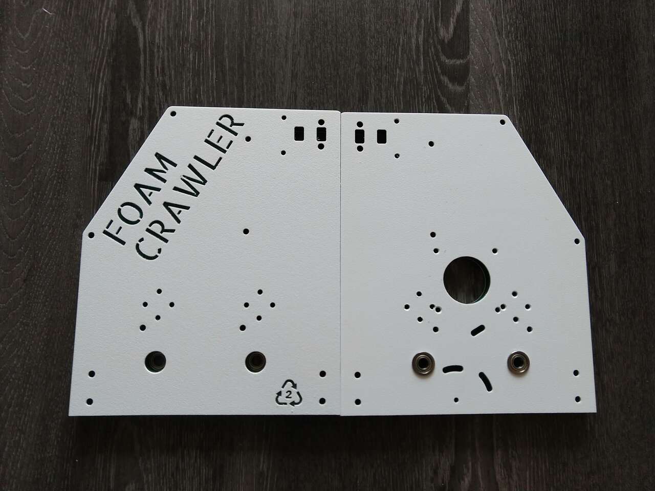 Side plates with flanged bearings inserted
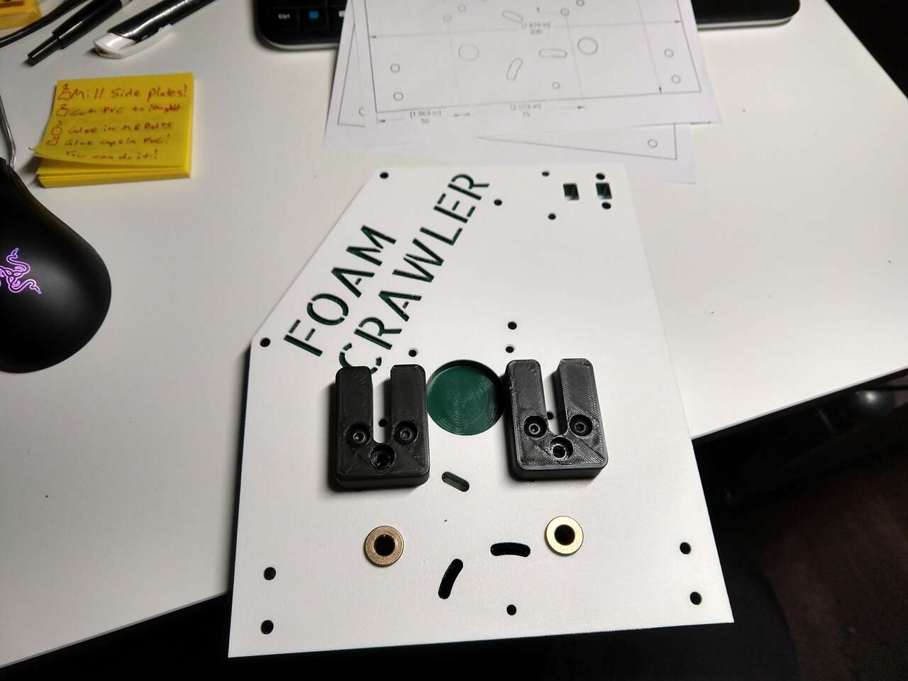 Upper roller cradles installed
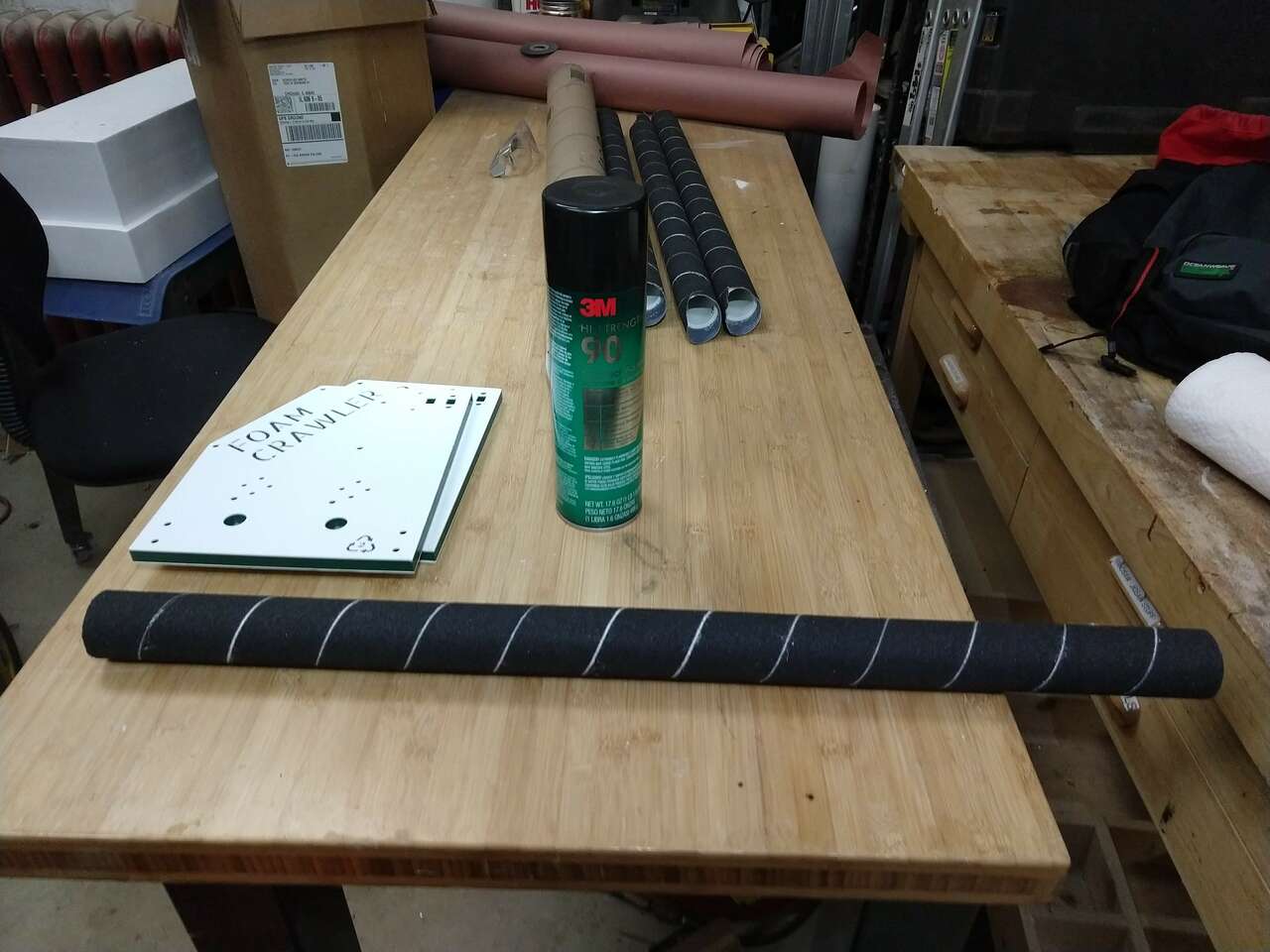
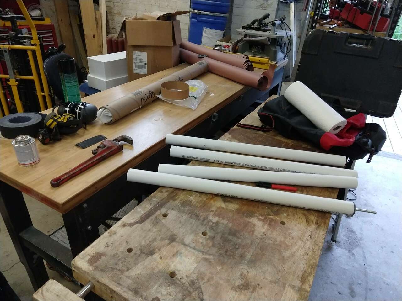 PVC rollers sanded and ready for grip tape glues on with 3M 90 adhesive
 How to mark grip tape for trimming
 grip tape done
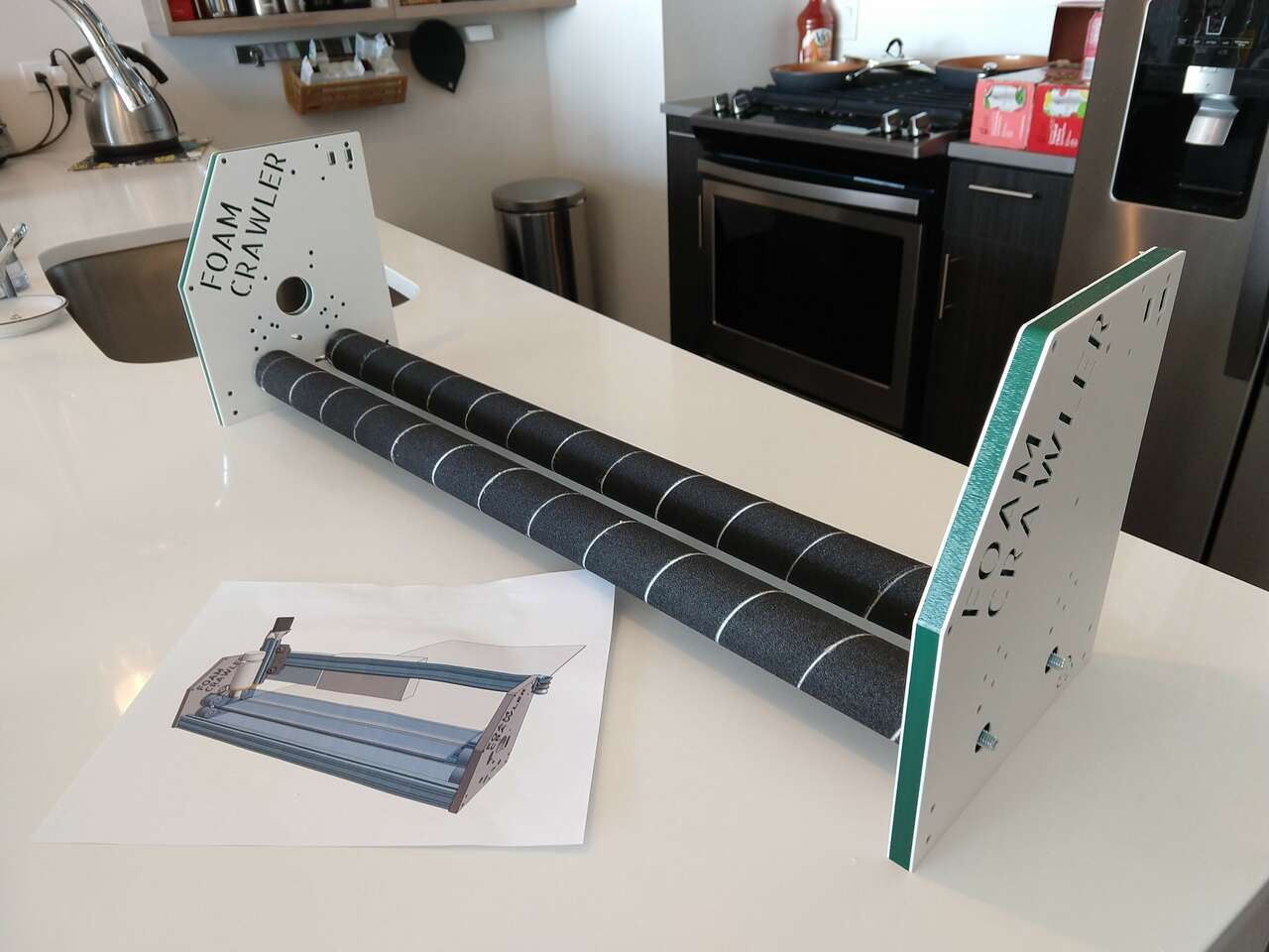 Lower rollers test fit
CAD files
See this link forOnshape CAD files of the Foam Crawler Assembly: FoamCrawler CNC
727 Glider
My [727 Glider Project] made from white CNC cut Depron foam sheet, with tab and slot construction.