20. Final Project Presentation
Foam Crawler: A CNC Foam Sheet Cutter
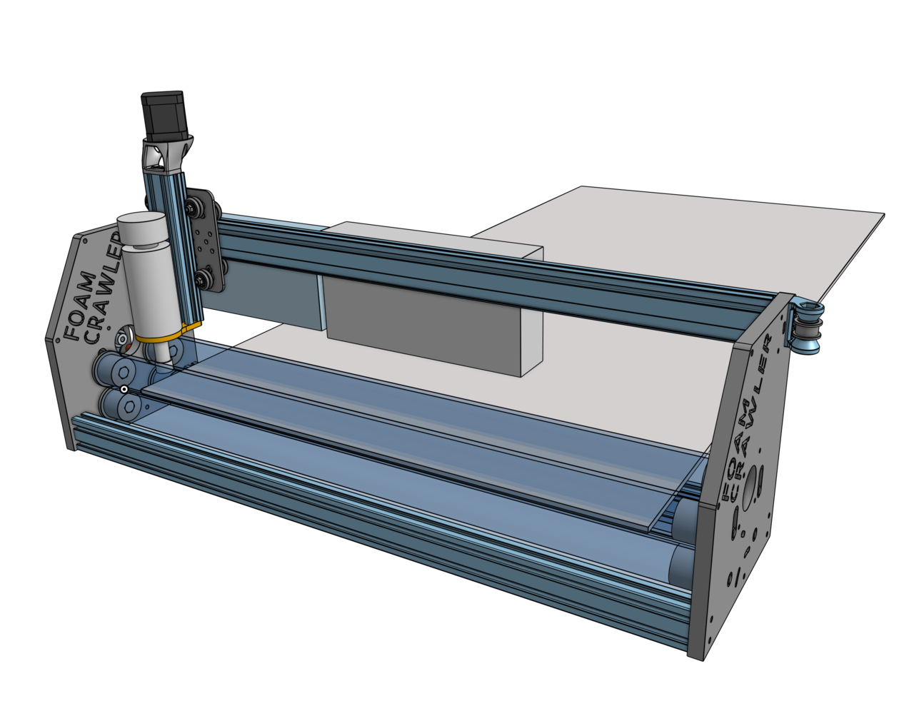
My Final Project is the Foam Crawler, a CNC machine that cuts foam sheets with a 1.6mm diameter end mill powered by a 12,000 RPM spindle.
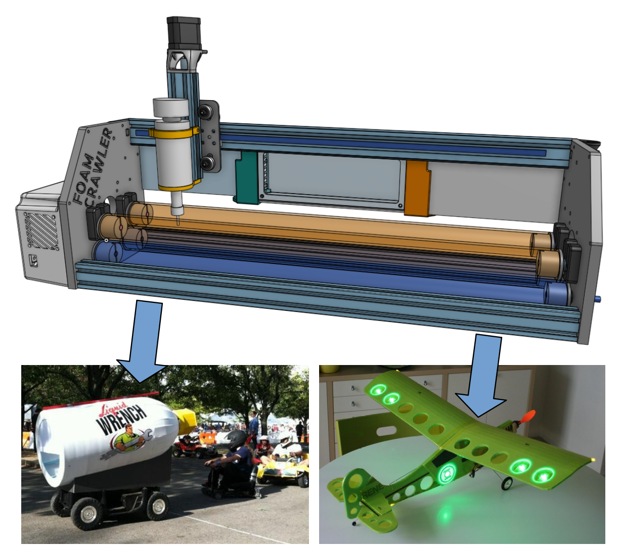 Slide of showing two examples of what the Foam Crawler can make. Left image is a small pace car with a foam body and base that looks like a giant can of liquid wrench. All the parts to make the body were made from CNC cut foam. The right image shows Radio Controlled airplane where the entire airframe is CNC cut foam.
Above is a video of the first ever Foam Crawler CNC Machine completed and operational on 2020-Aug-19. In the video the Foam Crawler is cutting a simple example to demonstrate its basic capabilities. See below for more details on what the Foam Crawler can do and how it was designed, fabricated and built.
What it can do
The Foam Crawler is a low-cost CNC milling machine that can cut 2D shapes from foam sheets up to 600 mm wide and 30 mm thick and an infinite length. These foam sheet shapes can be used to fabricate:
- Small and medium thin foam shapes
- Large interlocking foam shapes
- Casting Patterns (Match plate)
- Lost Foam Patterns
- Router templates (for cutting wood, plastic, aluminum)
- Fixtures and Jigs
 Small and medium thin foam shapes, in this example foam sheet parts to make a radio control airplane.
 In this example: A pace car that looks like a can of liquid wrench was made from interlocking sheets of foam shapes to make a giant spray can used as a theatrical prop.
 Lost Foam Casting In this case a foam pattern for sand casting an aluminum wheel
 Router templates (for cutting sheets of wood, plastic, or aluminum)
Things fabbed from foam sheets:
- Aircraft (my favorite)
- Casting patterns (for casting plastic, cool and metals..so hot!)
- Router guide patterns for cutting wood and aluminum
- Super large interlocking foam objects (large glowing LED foam sculptures)
- Vacuum Forming patterns
- Antenna soldering and bending fixtures, for complex 2D and 3D shapes (helical, circularly polarized, etc.)
Advantages of foam fabrication
- Can be cut on low cost cnc machines
- Material (foam) costs are low
- Cuts Fast using minimal cutting forces
- Light weight
- Easy to fill and finish with light weight spackle, gorilla glue etc.
- 2D X Y foam shapes can be stacked in Z to make 3D shapes
- Can make patterns for casting metal with lost foam and sand casting techniques
Foam patterns and fixtures
CNC foam shapes can be used as master patterns and templates. These patterns can be used in conjunction with a router and a ball beating guided bit to route complex shapes from wood, plastic, and aluminum. The edges and tops of the foam can be hardened by brushing on epoxy to make a more durable guide surface. The top of the foam could be laminated with carbon fiber, fiberglass, or burlap and epoxy to make more durable patterns.
Foam drill fixtures can be used to very accurately located drilled holes by using the foam base pattern to make a HDPE drill fixture. These fixtures that will accept drill bushings. The HDPE secondary pattern would be much more durable and could be used over and over in short to medium production runs. The HDPE pattern could also be used to make and aluminum pattern that would be capable of high volume production.
Project Management Timeline
| Target Date | Task |
|---|---|
| June 23 | Basic CAD Design of CNC Foam cutter |
| July 2 | Ready or purchase final control boards and touchscreens |
| July 11 - 17 | Purchase timing belts, pulleys, M8 hardware |
| July 12 - 22 | Purchase bushings, taps and tap drills |
| July 4 - 18 | Advanced CAD Design |
| July 19 - 25 | Manufacture and assemble prototype machine structure |
| July 26 -Aug 1 | wire and test machine |
| Aug 2 - 8 | Troubleshoot machine, iterate, improve |
| Aug 9 - 15 | Present machine to Fab Academy |
Specifications:
Work Envelope: 600 mm x 30 mm x ∞ mm Machine Dimensions: 860 mm x 260 mm x 450 mm
Detailed Overview
For my Fab Academy 2020 Final Project I designed and built a CNC Foam Cutter. I have always wanted to make a CNC foam cutter that is more capable and easier to use compared to my first CNC machine I built the PhlatPrinter.
The laser cutter is one of the most powerful and easy to use machines in a Fab Lab. However Laser cutters are extremely expensive for a individual. Laser cutters are not easy to install and run at home.
A CNC foam sheet cutter is easy to use and is easier to install and run at home. Most importantly is that a CNC foam sheet cutter can be fabricated in a Fab Lab for around $300. A foam cutter can easily process 60cm x 120cm foam sheets (2x4 feet). This is much larger than a small laser cutter, rivals a large bed laser cutter, and is about 25% the work area of a full size shop bot.
The casting and molding Fab Academy session also reminded me that large molds and patterns can be made on a CNC foam sheet cutter. Stacks of foam sheet shapes make great sand casting patterns.
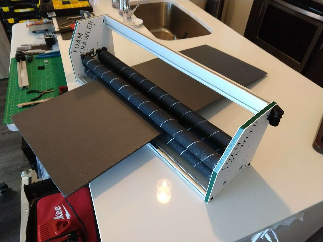
This machine will be the first of a series of machines for my Fab Shop project. I call it the Foam Crawler because the twin drive rollers appear to crawl across the foam. Also this machine has a shape and look similar to a Star Wars Sandcrawler.
Background
I built a wooden PhlatPrinter CNC machine from a kit in 2009. The PhlatPrinter allowed me to digitally design and fabricate RC aircraft from CNC cut foam sheets.
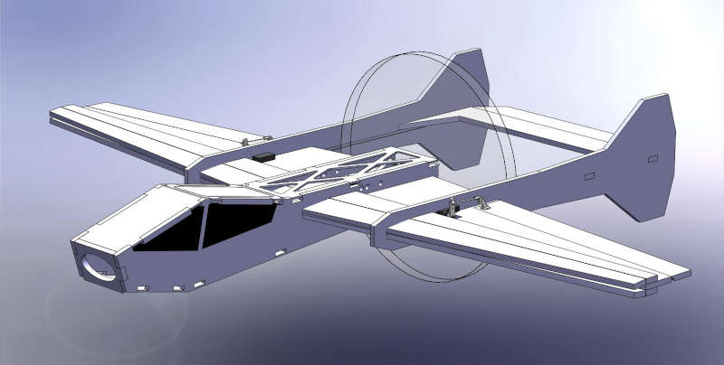
My Prizm Hex RC Aircraft CAD design:
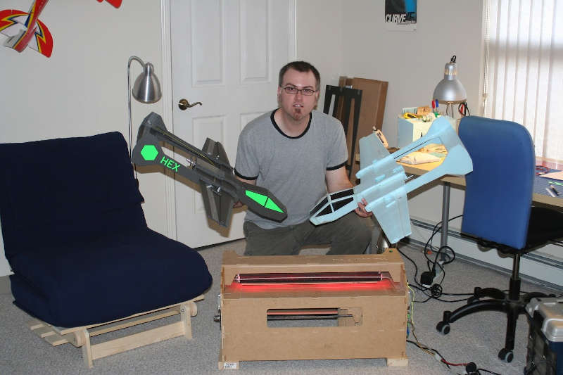
 Two assembled Prizm Hex RC Aircraft after being CNC cut on my PhlatPrinter.
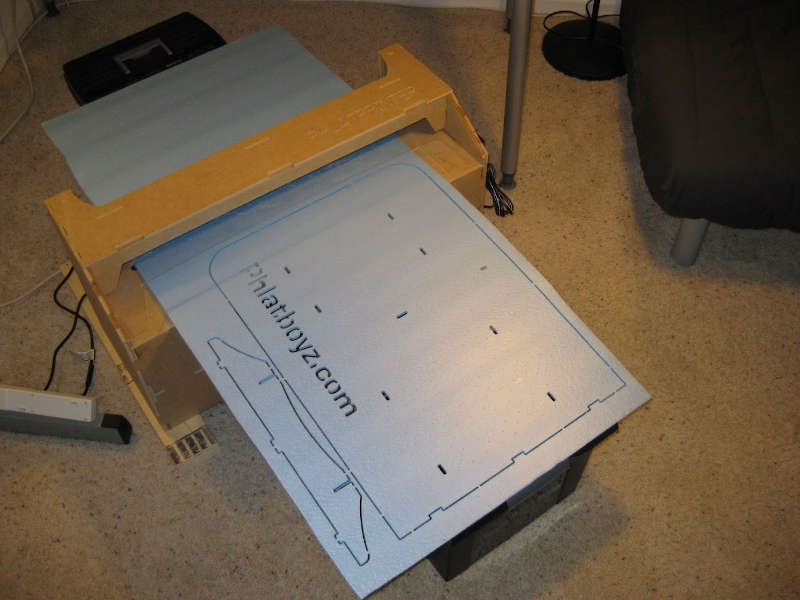
 My Phlat printer cutting parts.
I have upgraded the PhlatPrinter to improve its performance and reliability over the years. In the photo below I redesigned and entirely new Z and Y axis gantry using MakerSlide and laser cut parts. This new gantry greatly improved the reliability and cutting speed of my PhlatPrinter.
I have always wanted to design and build my own foam cutting cnc machine from the ground up, adding features I have wished for after years of building items with foam sheet.
CAD
CAD Concept 1 Complete
2020-Jul-15 Wednesday
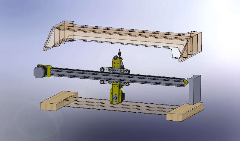
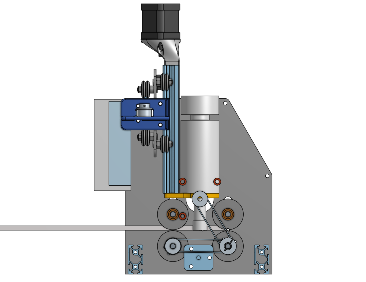
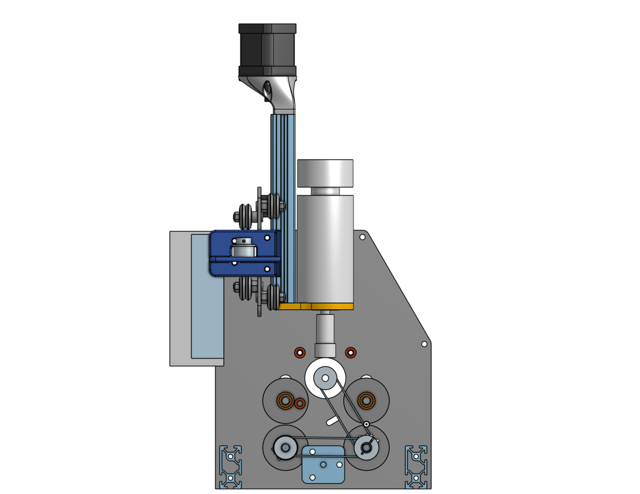
 This concept shows how the rollers will drive the foam through them and basic spindle and cutting tool position.
Breaking Procrastination
2020-Jul-18 Saturday
I have been procrastinating for weeks now… I think I am afraid of… not being able to complete my Fab Shop machines. Afraid of not being able to guide others in building machines successfully. I have a huge block to use the practical down to earth with my hands machinist skill set I learned and used every day when I was so much younger. Have I been corrupted by slowly drifting towards a Manager who works less with my hands. Have I broken my pact I made with myself years ago:
“Never stop practicing the work of the workers yourself.”
“Always do direct hands work. This will allow you to stay connected with and understand workers. Do not become those who hold the workers down with their fancy speeches, and un-worked hands and corrupted excuses of why they get more than the workers.”
I am a hard working, hands on, Midwesterner. I deeply love that kind of work, so much so it does not seem like work when I do it. I haven’t done as much of that work as I would like the past few years. My job as a Manager is important, going forward however, I will do much more hands on work and delegate, say no to work that is not hands on.
Hello hands on, I am back!
Today I return to hands on stuff, adding my new Fab Academy skills.
CAD Assembly Design
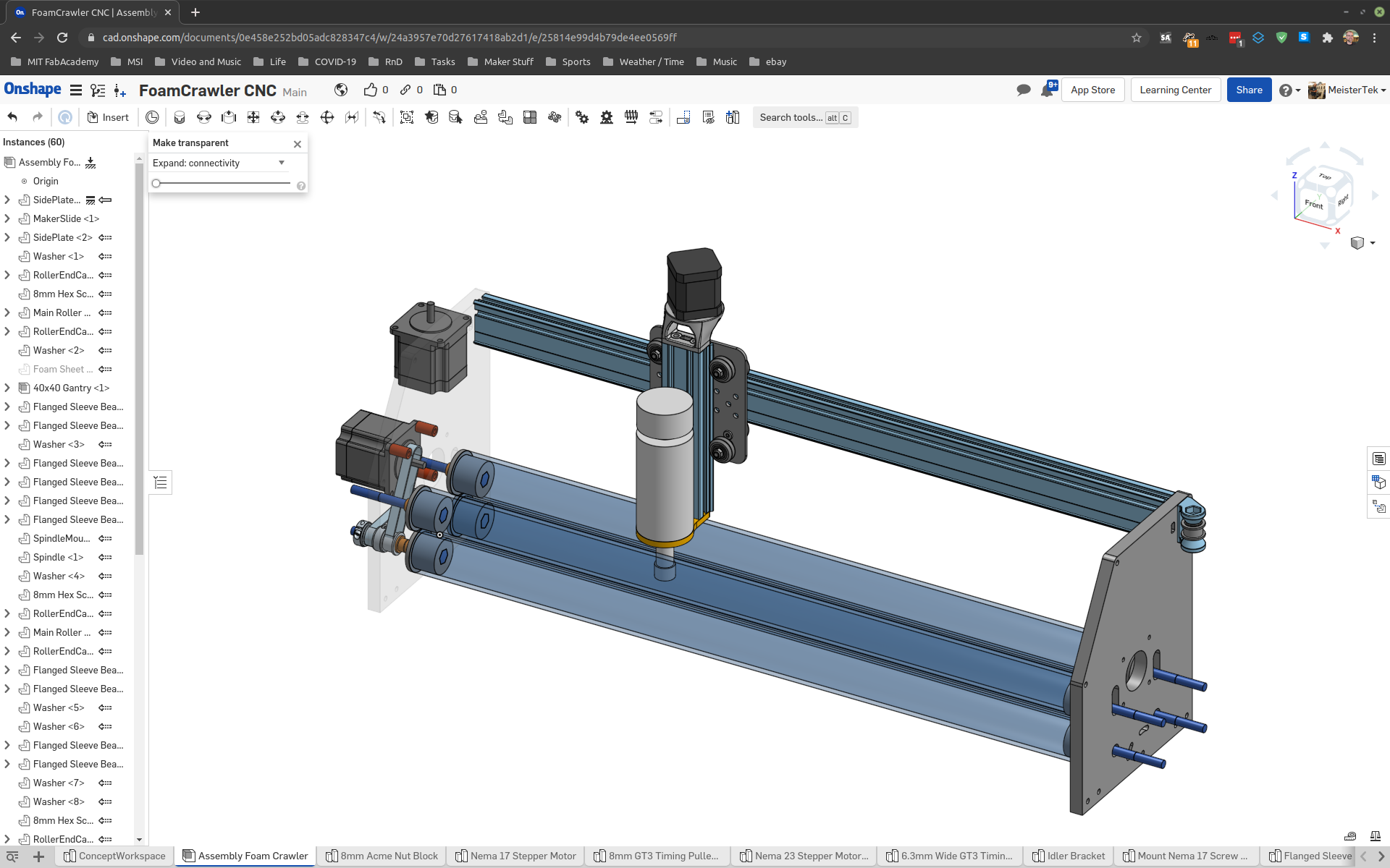
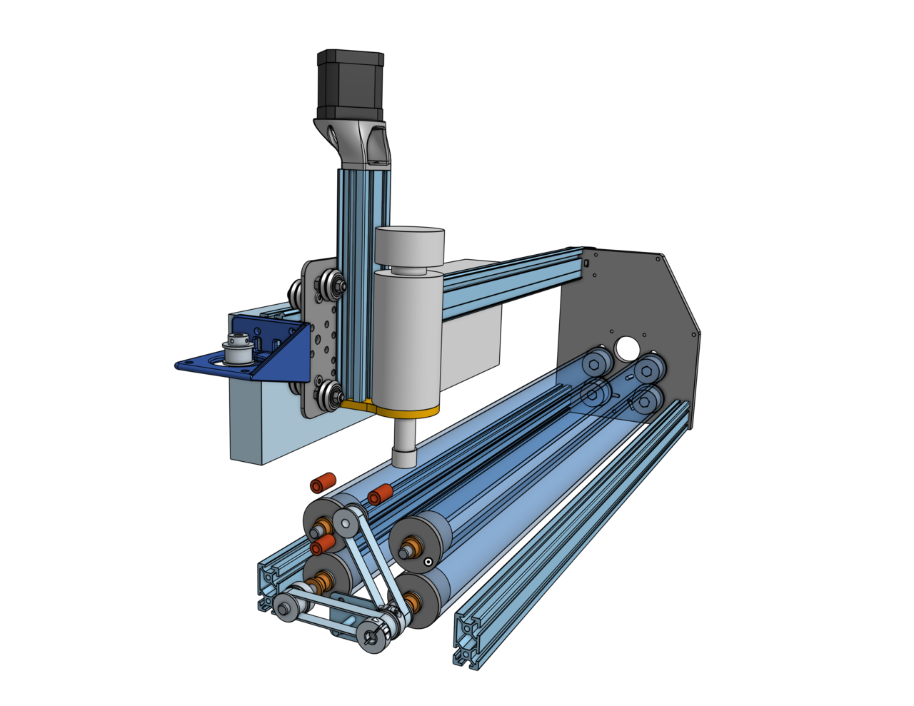
Yesterday and last night I got a lot of work done. Here is my assembly model as of Sunday 3:30 AM
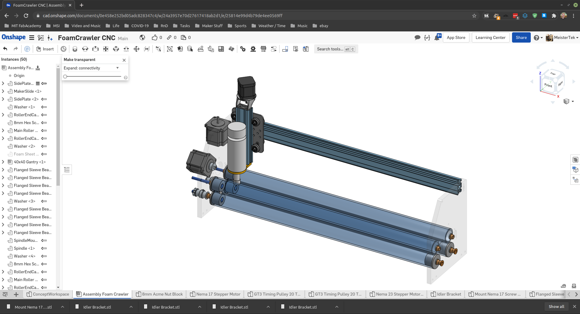
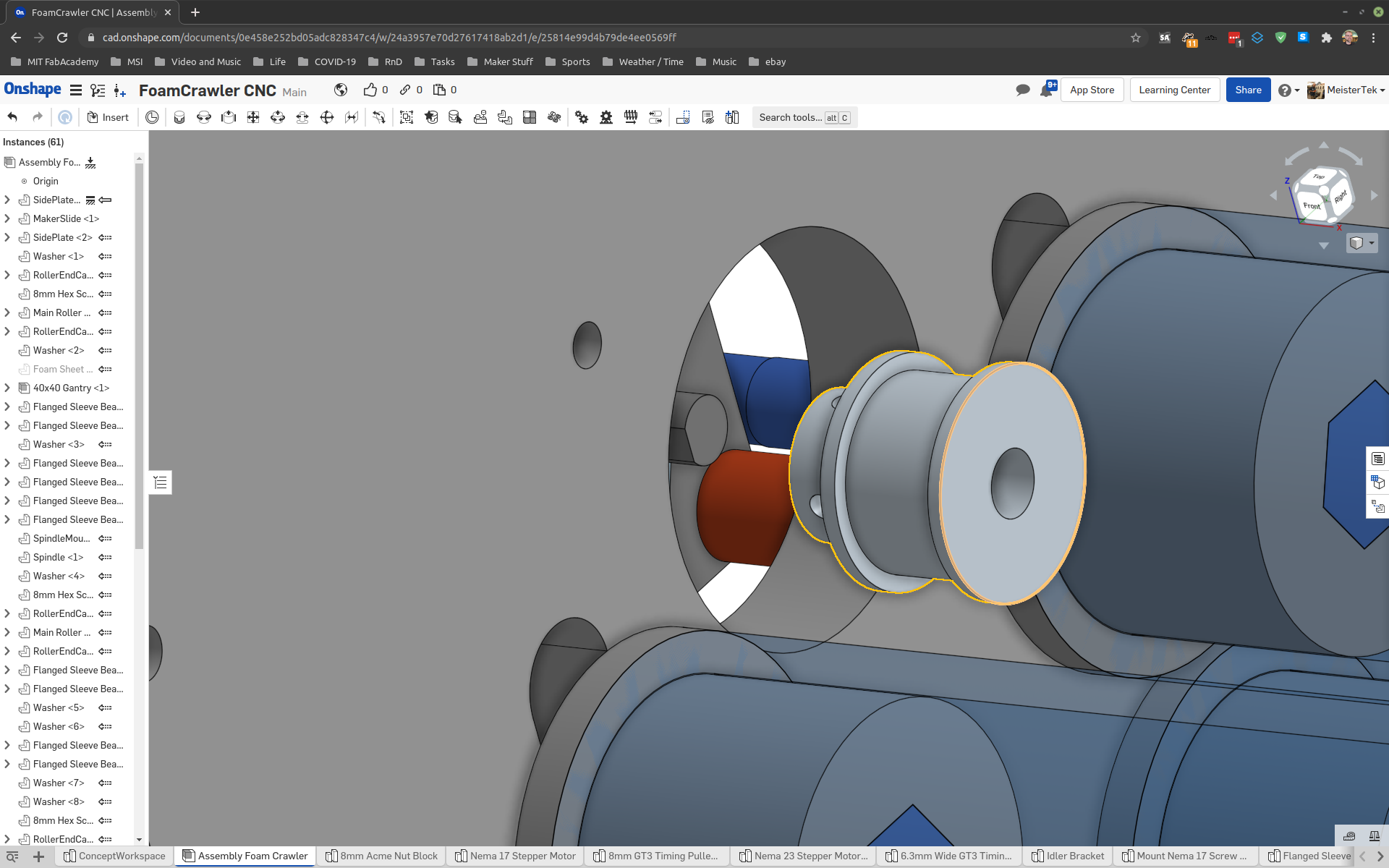
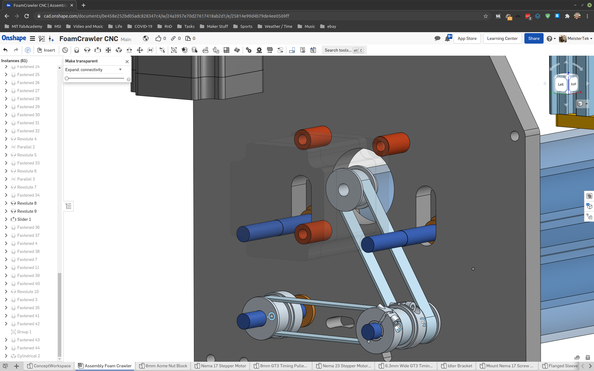
It’s been some time since I have done virtual assembly using CAD and,,, boy is it fracking powerful. This is the first time I have explored the assembly mates that Onshape uses. They work really well once you understand them. Onshape has excellent documentation.
At this point in time I have over 60 parametric assembly mates, and a BOM of 29 unique parts and a total parts count of 118.
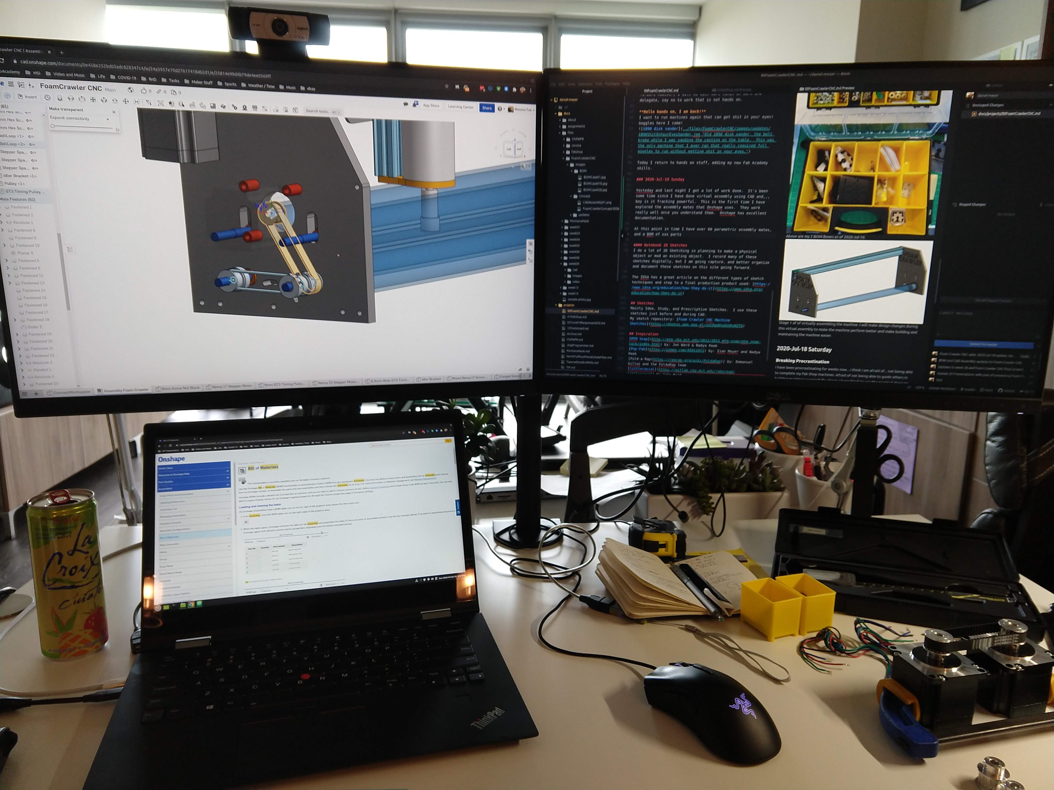
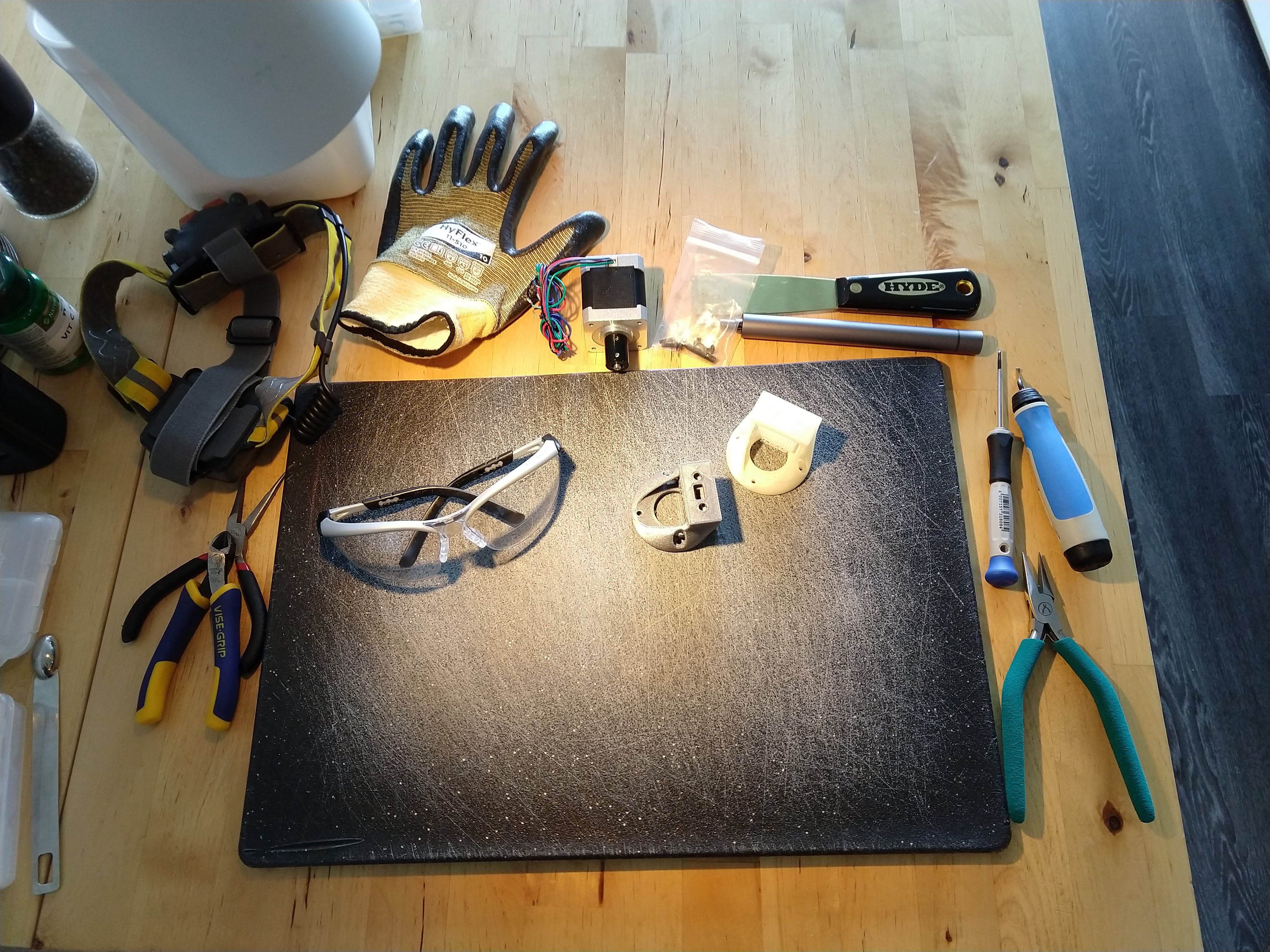
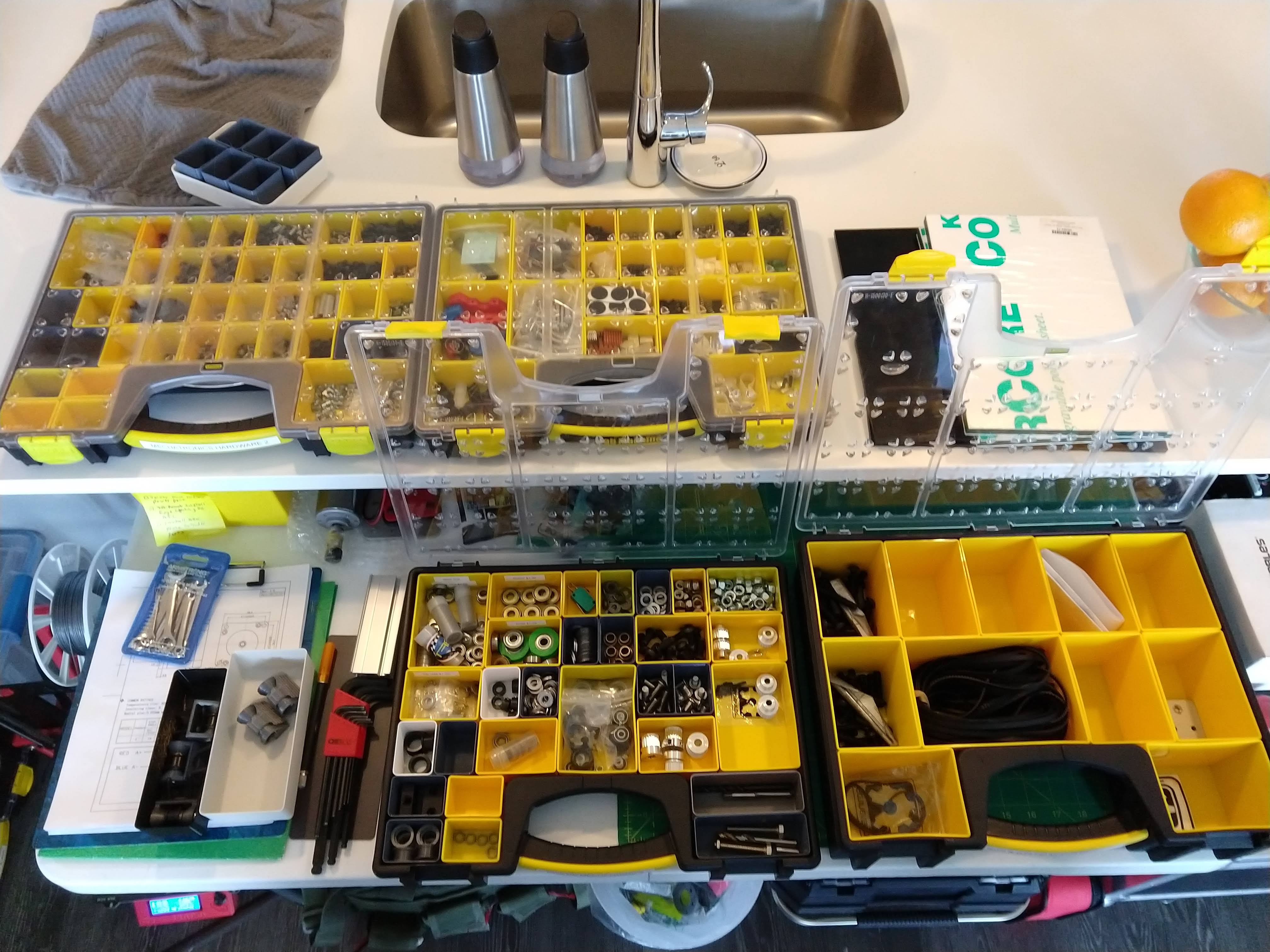
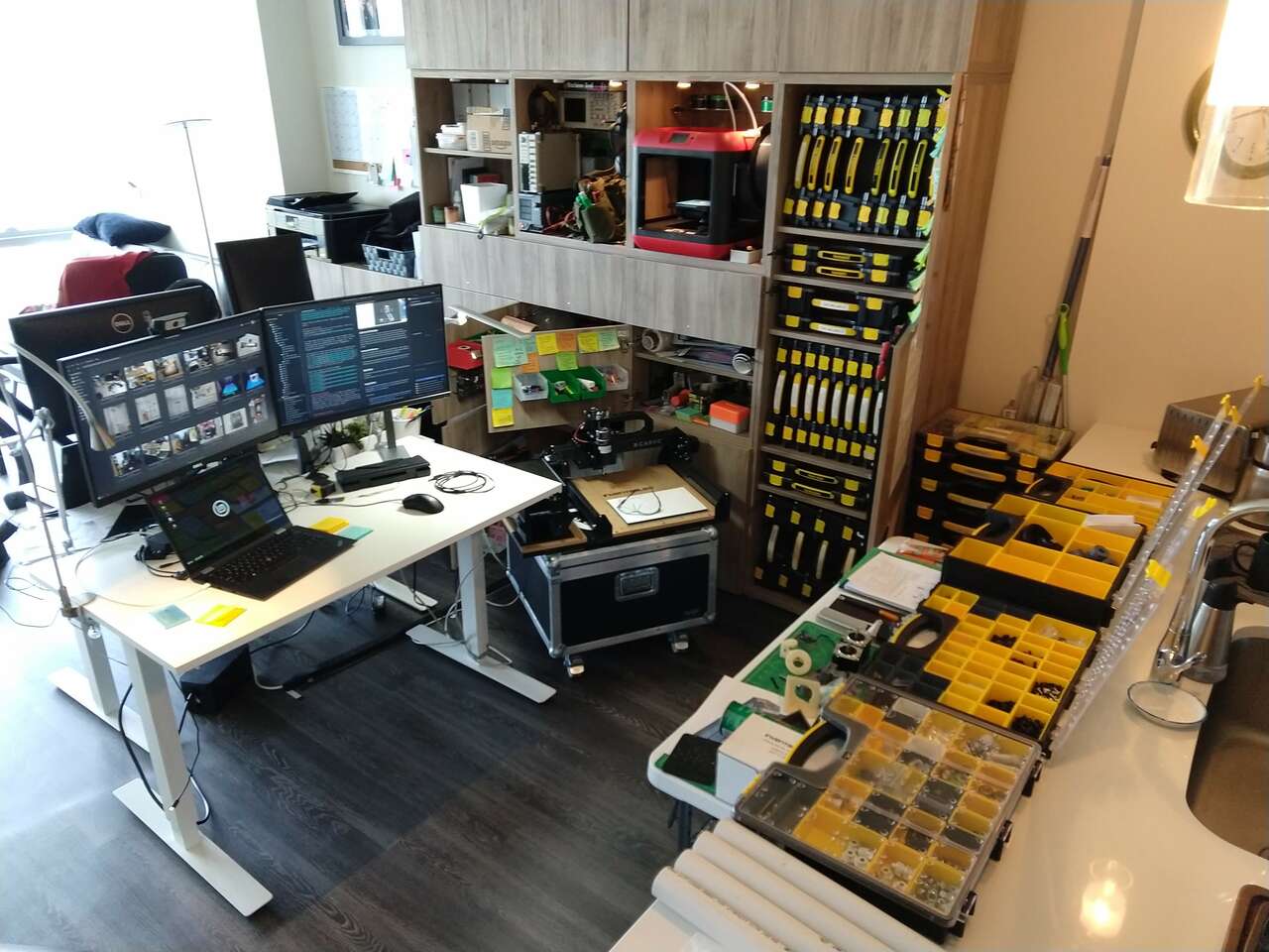
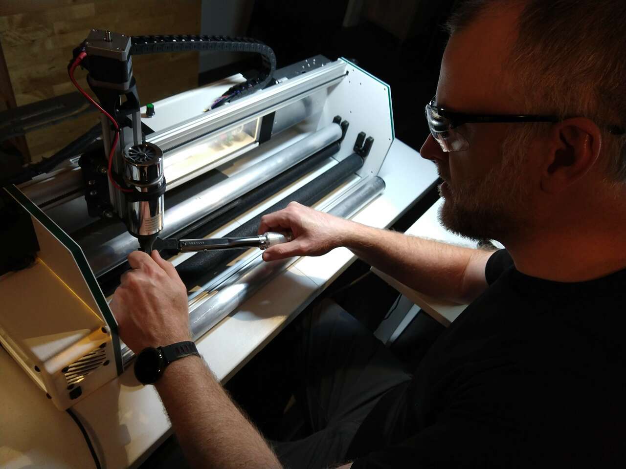
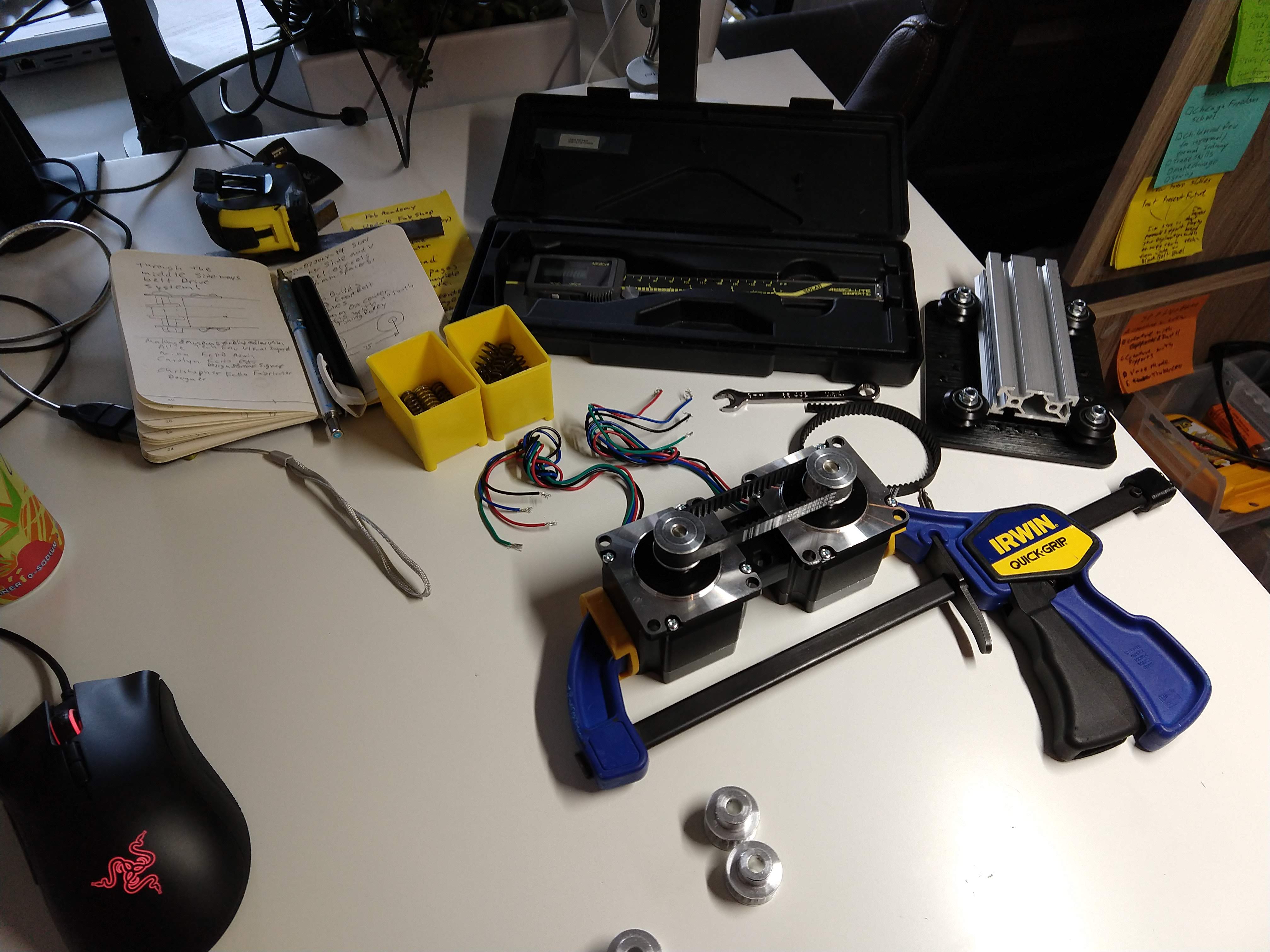 Above are some shots of my workspace as I design, 3D print, test and assemble in real and virtual worlds.
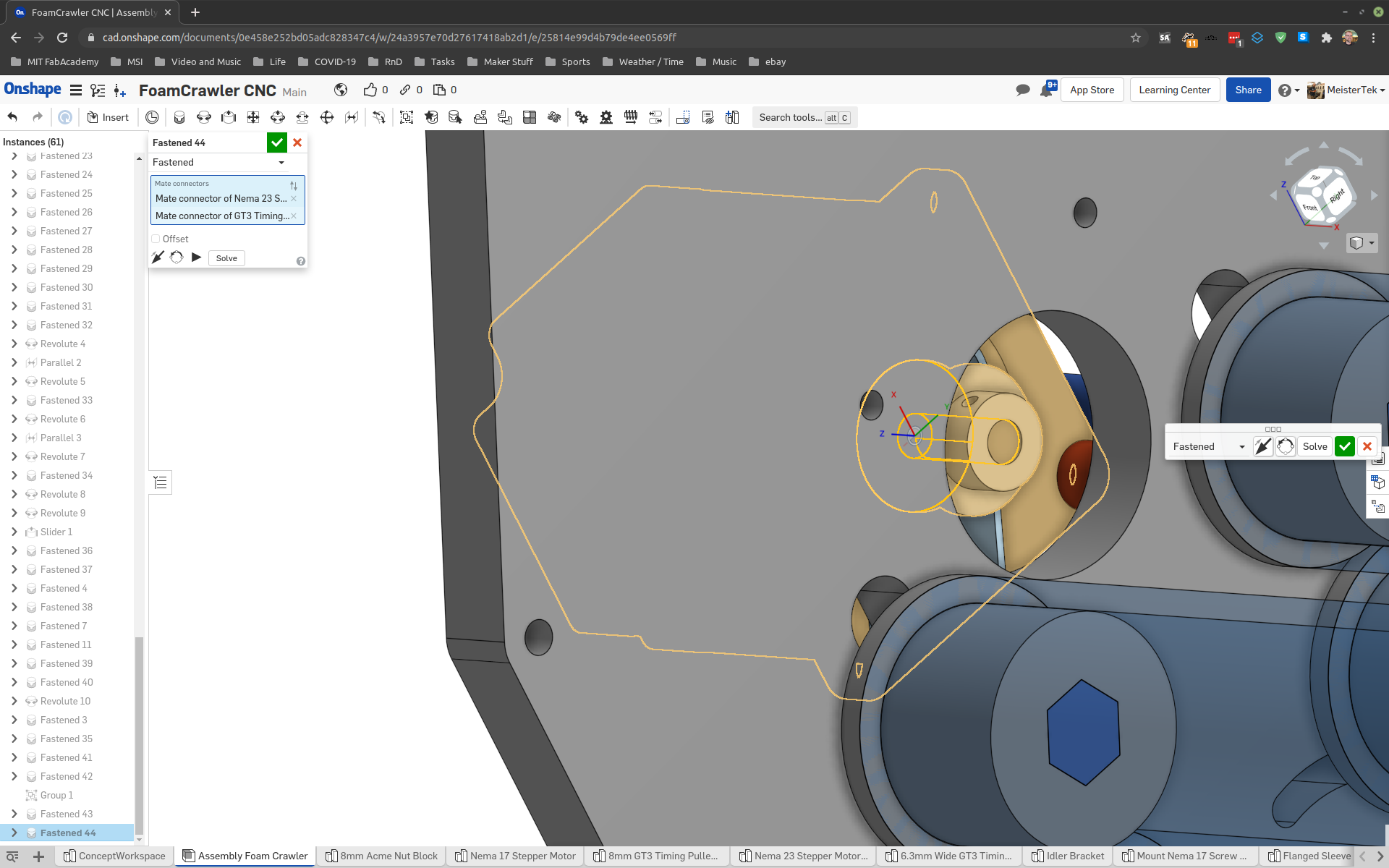
More screen captures of virtual assembly:

Final CAD Checks
Time for final checks of X, Y, Z ranges in parametric CAD. Double check drive system geometry.
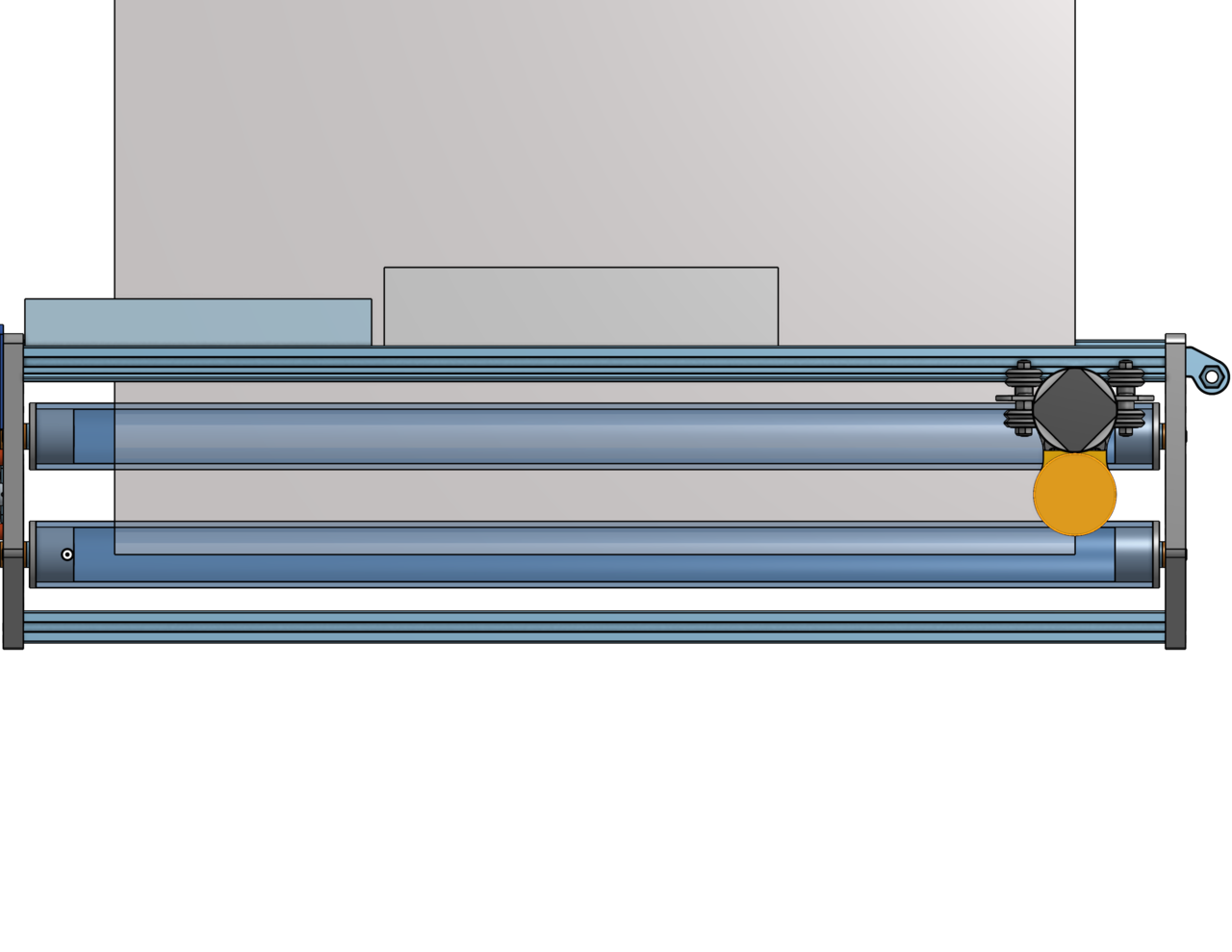
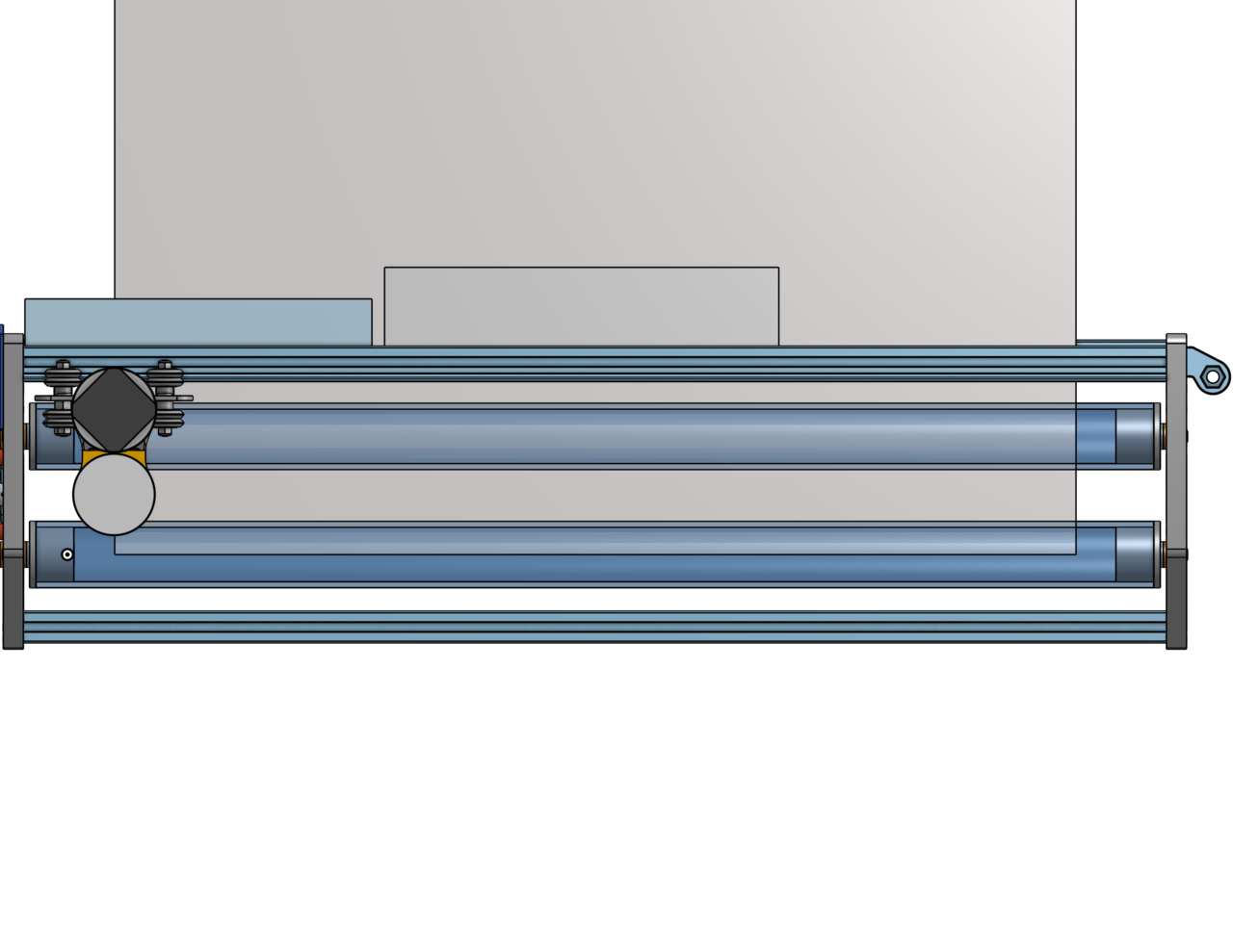

All looks as good as it’s going to get!
CAM
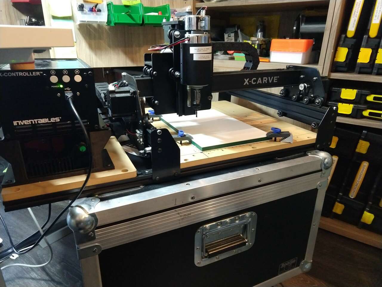
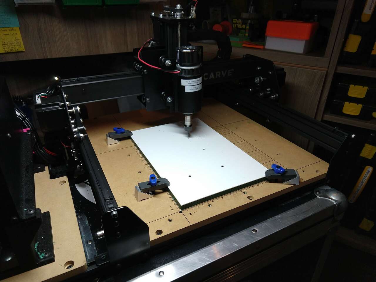
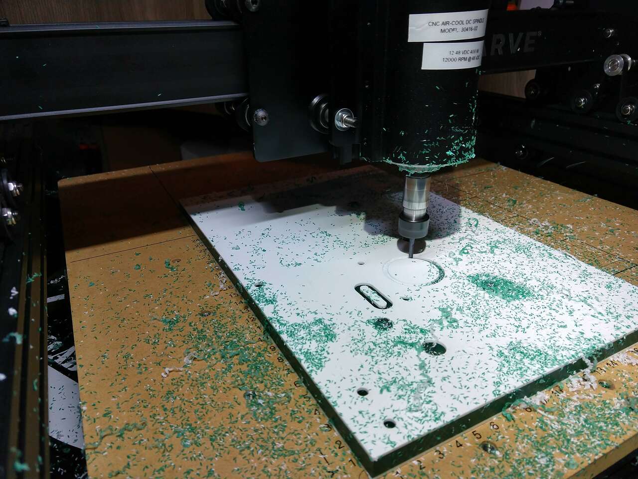
Milling HDPE Side Plates
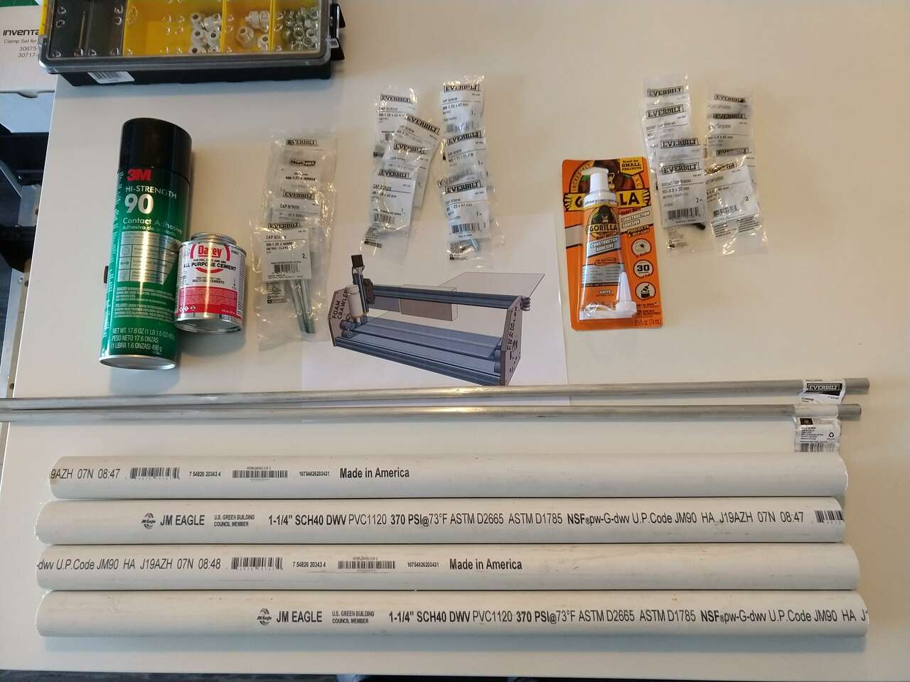
Time to mill the HDPE side plates on the 250x250mm X-Carve I have here at home. I have 3D printed all the parts needed. I went to Home Depot and purchased PVC pipe and fasteners that haven’t arrived from McMaster yet, PVC pipe is much cheaper than from McMaster anyway.
 Hold Downs
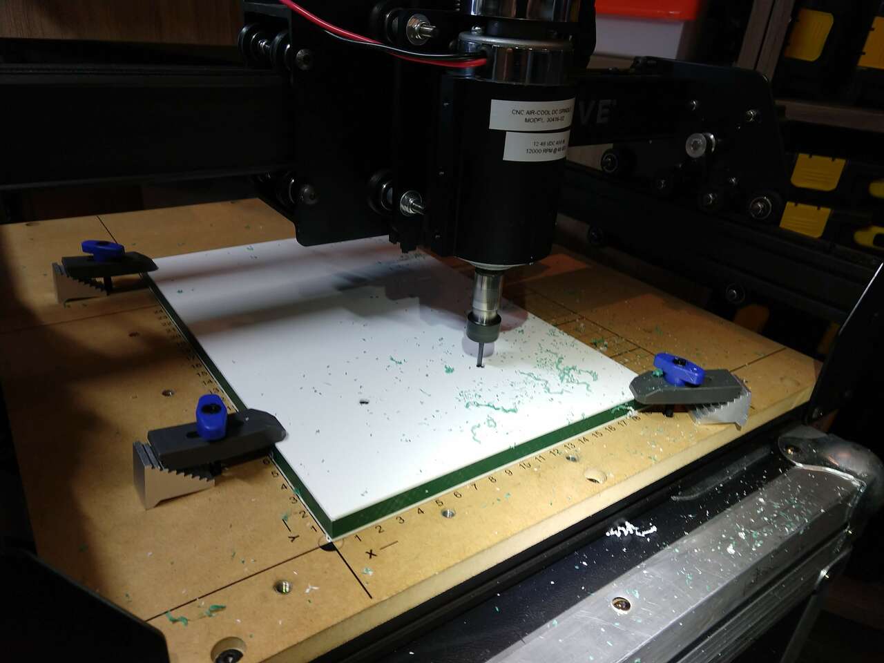

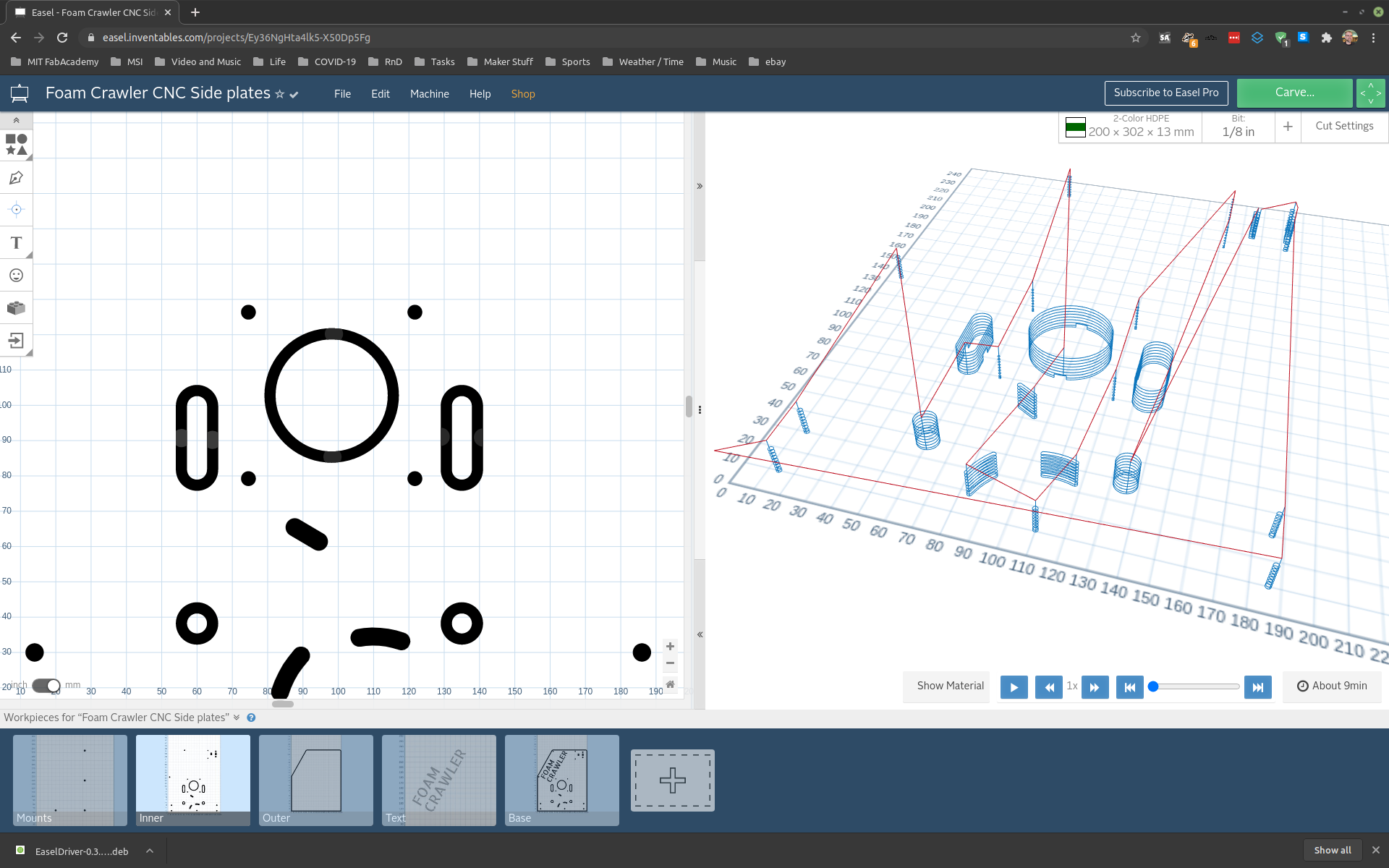 Inner Milling
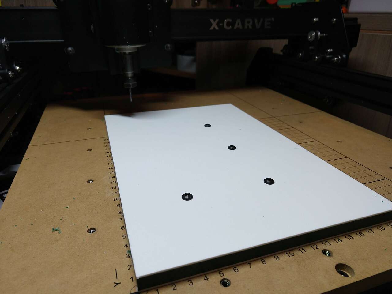
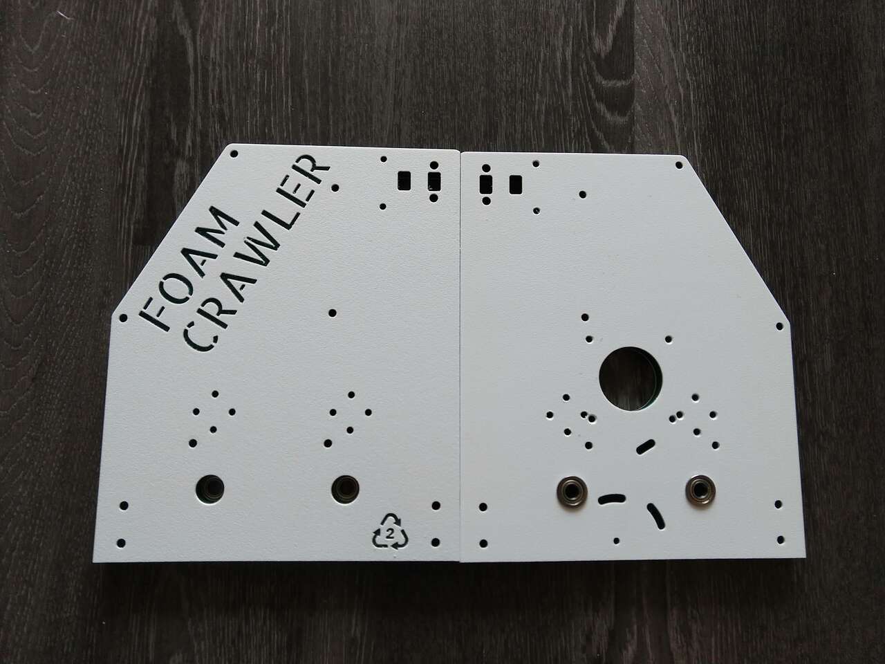
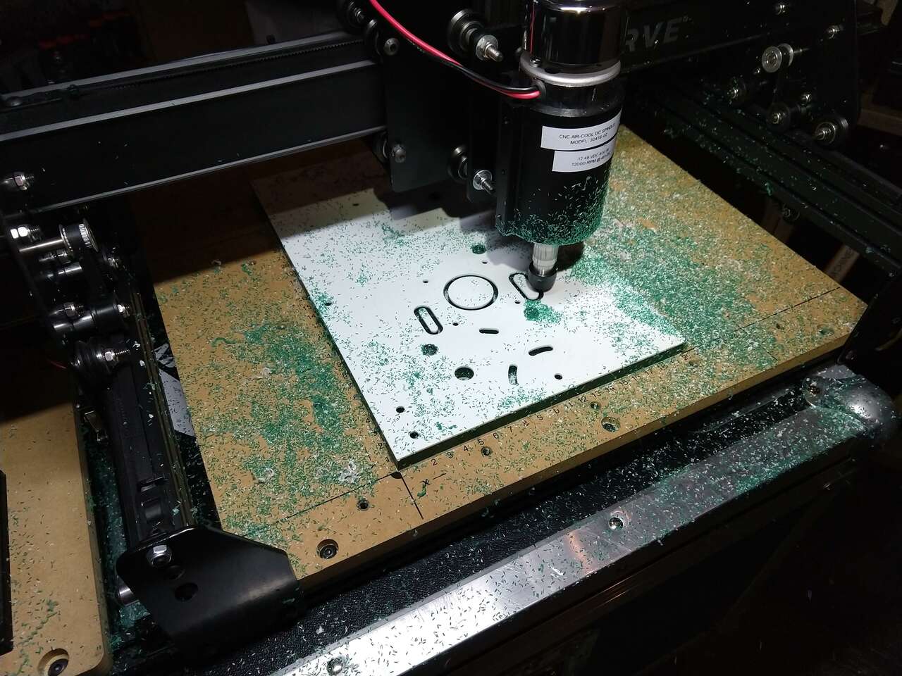 Outer Profile Milling
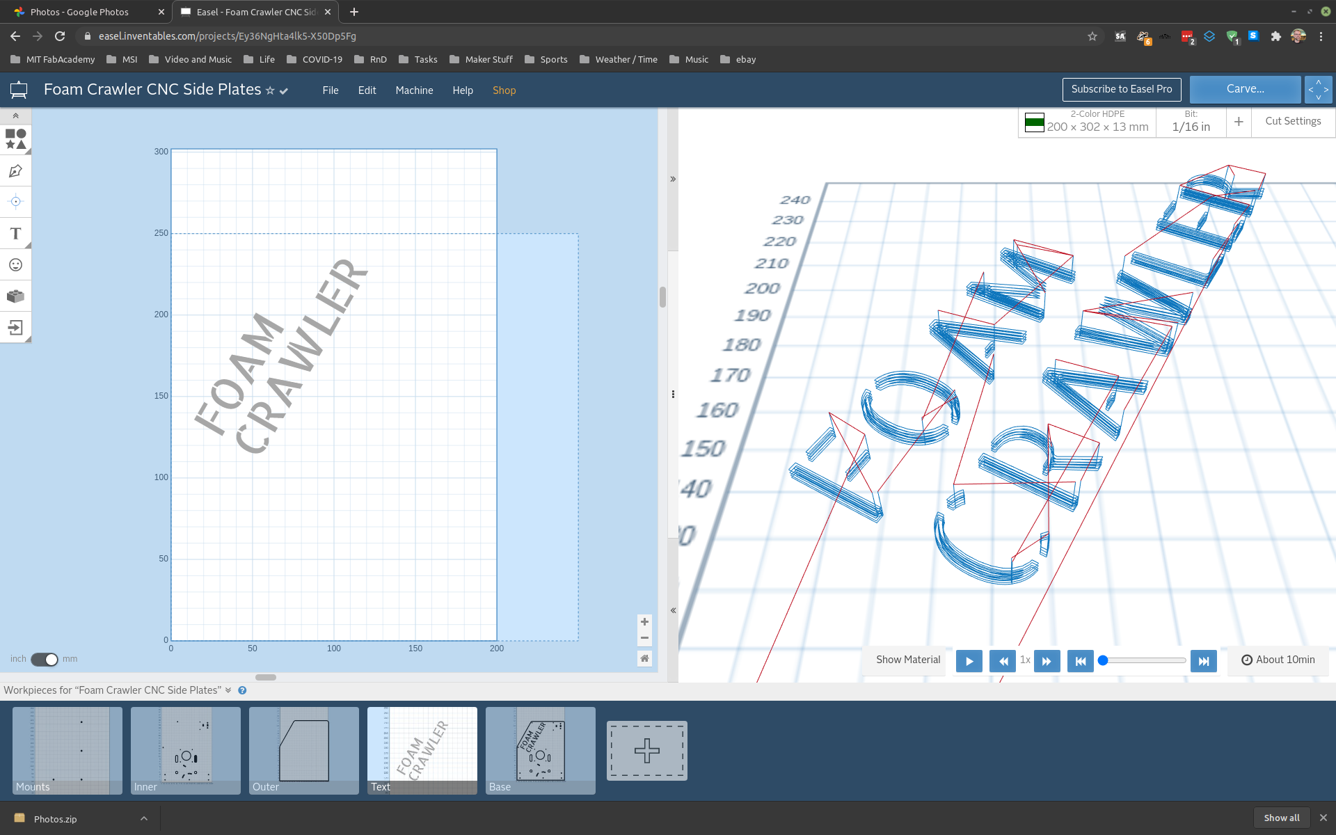
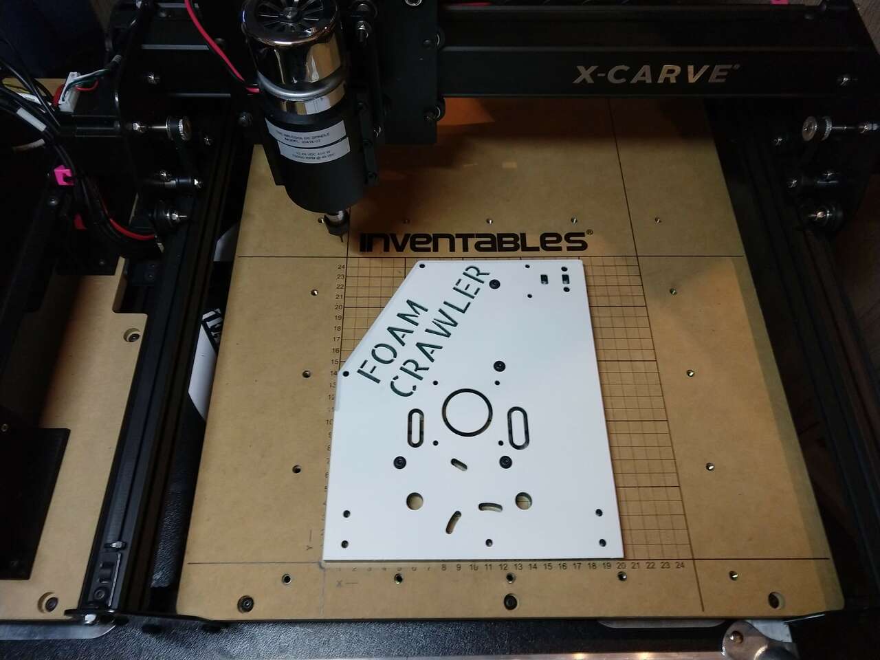
 Text Milling
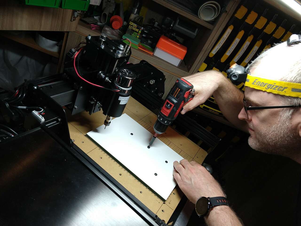
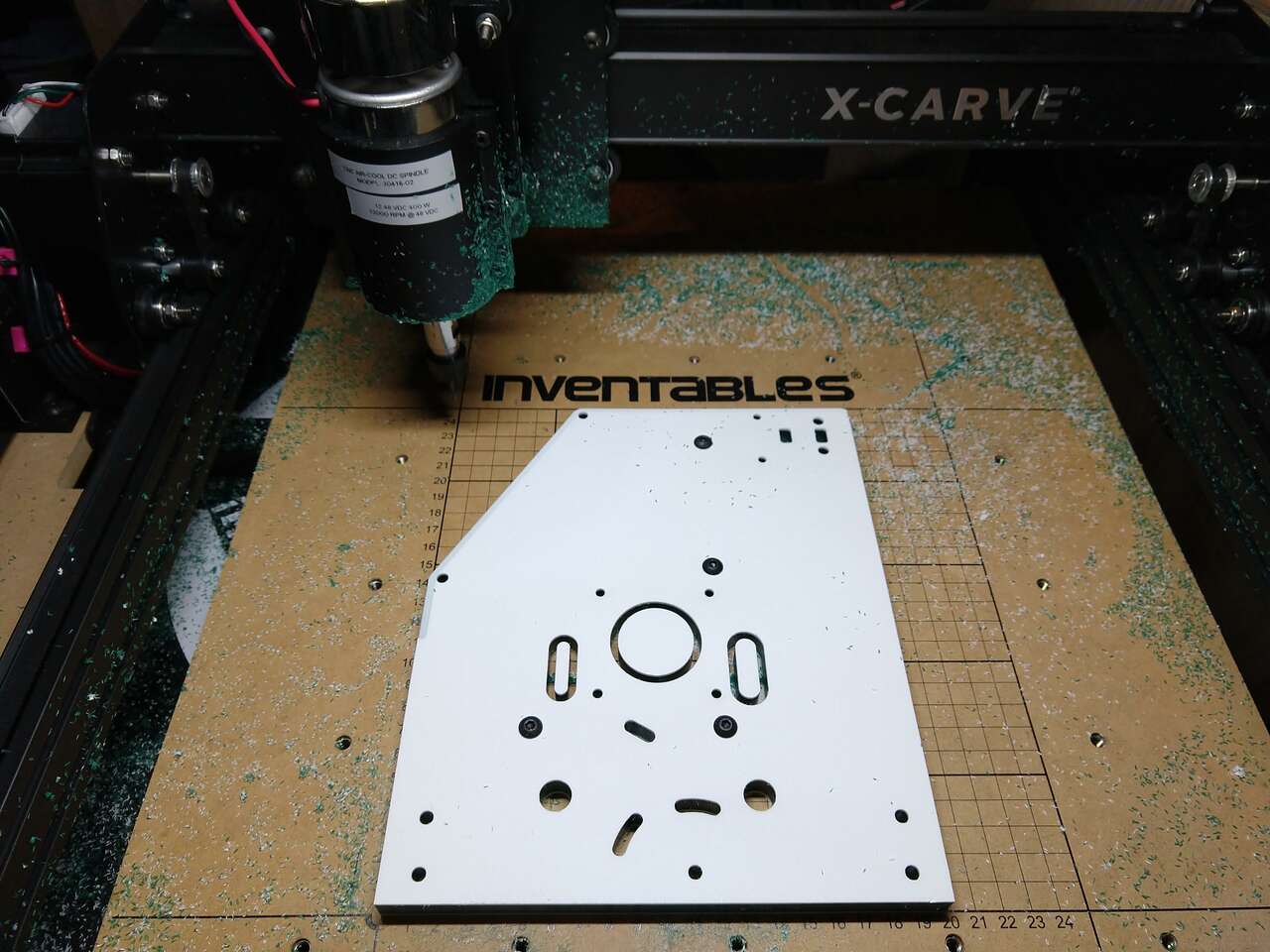
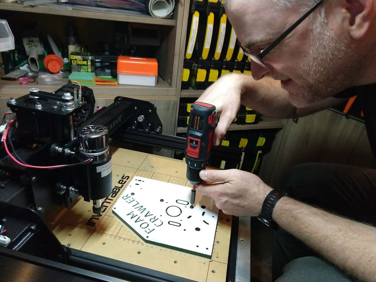 Removing hold downs
Assembly
Roller Grip Tape
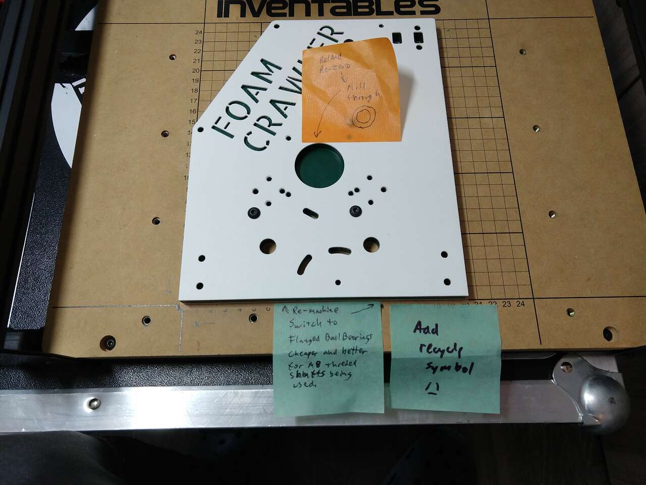 Corrections and updates
 Side plates with flanged bearings inserted
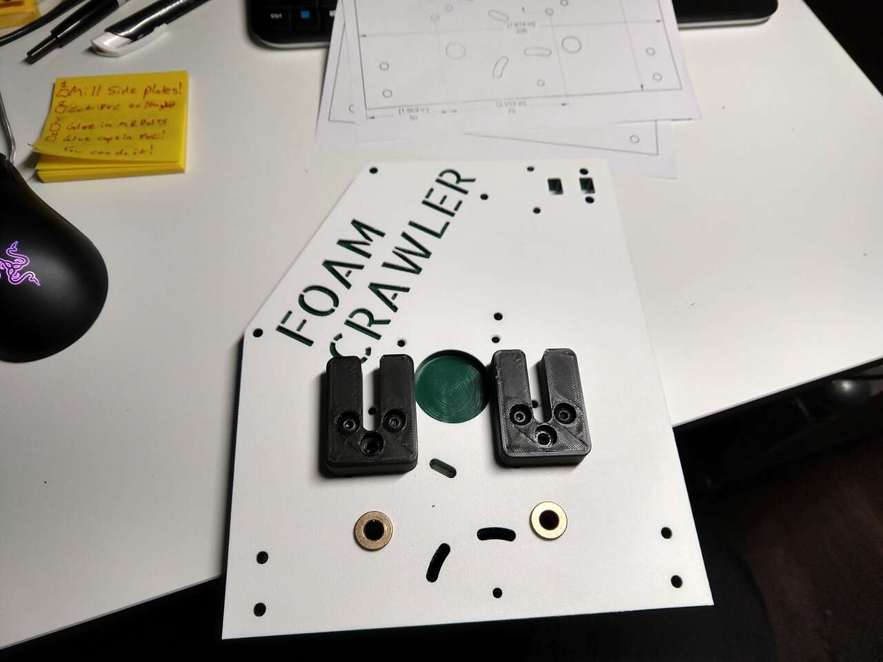 Upper roller cradles installed
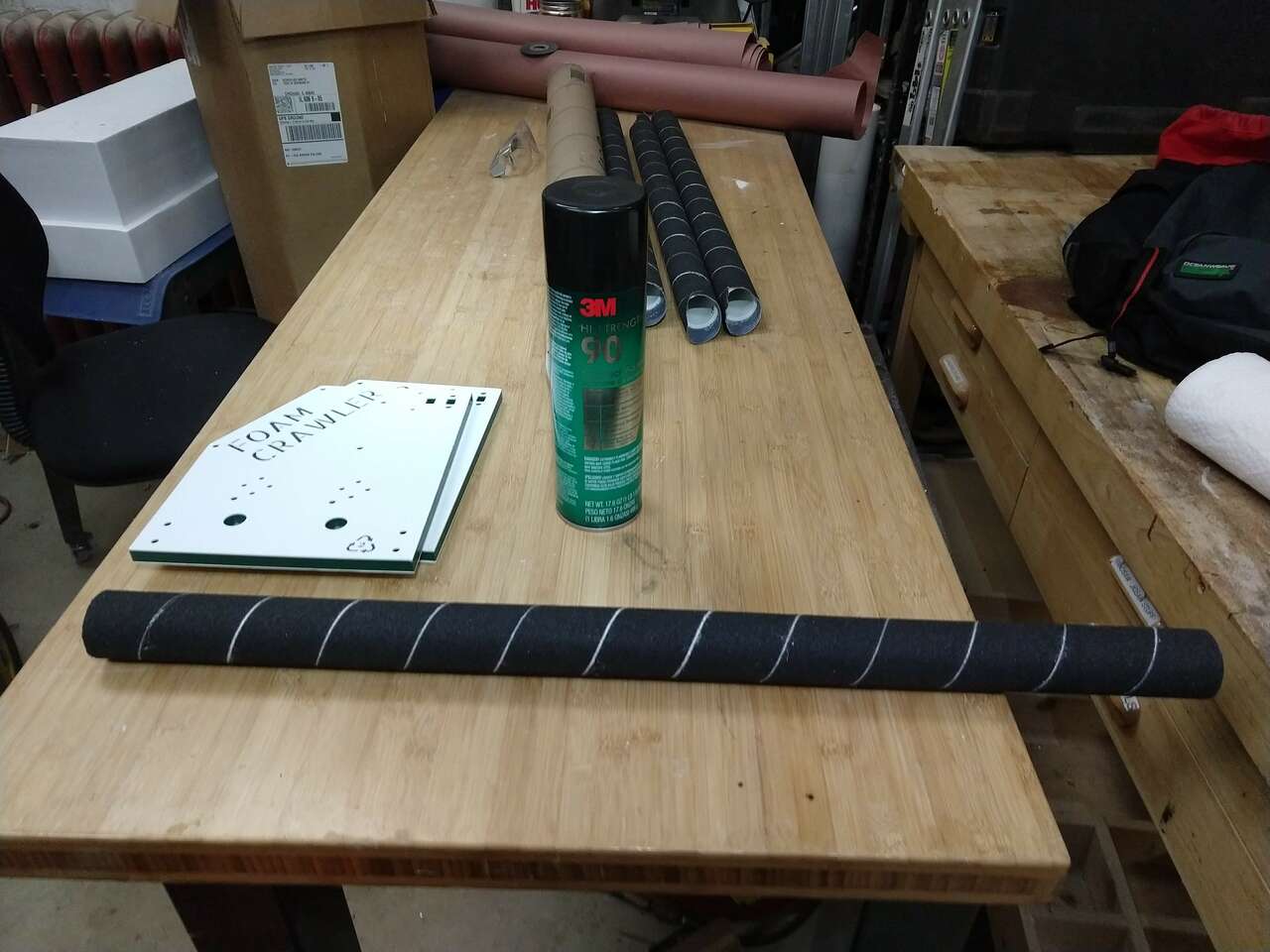
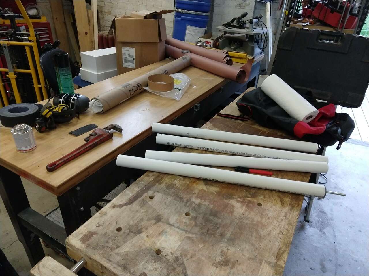 PVC rollers sanded and ready for grip tape glues on with 3M 90 adhesive
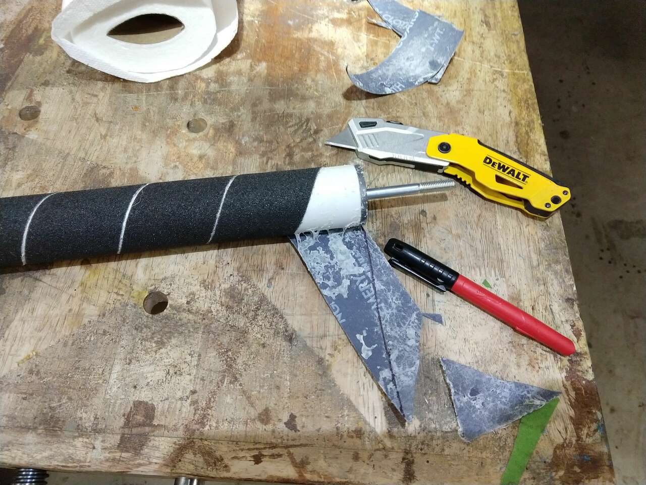 How to mark grip tape for trimming
 grip tape done
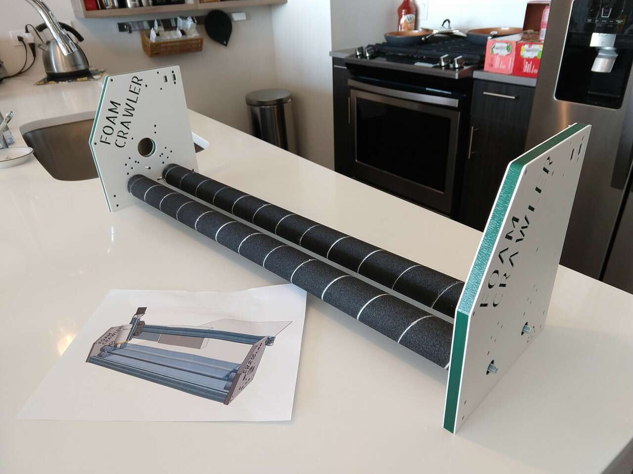 Lower rollers test fit
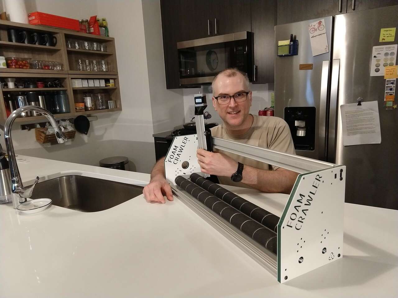 Z axis hand placed
 Upper rollers on foam
 Start of drive assembly
PVC Pipe too Wobbly
 Testing rollers with hand feed and foam inserted. PVC pipe is not straight enough, leading to wobble and gaps, and loss of grip on foam. Upper rollers need to be heavier, since a quick y move causes the rollers to slip.
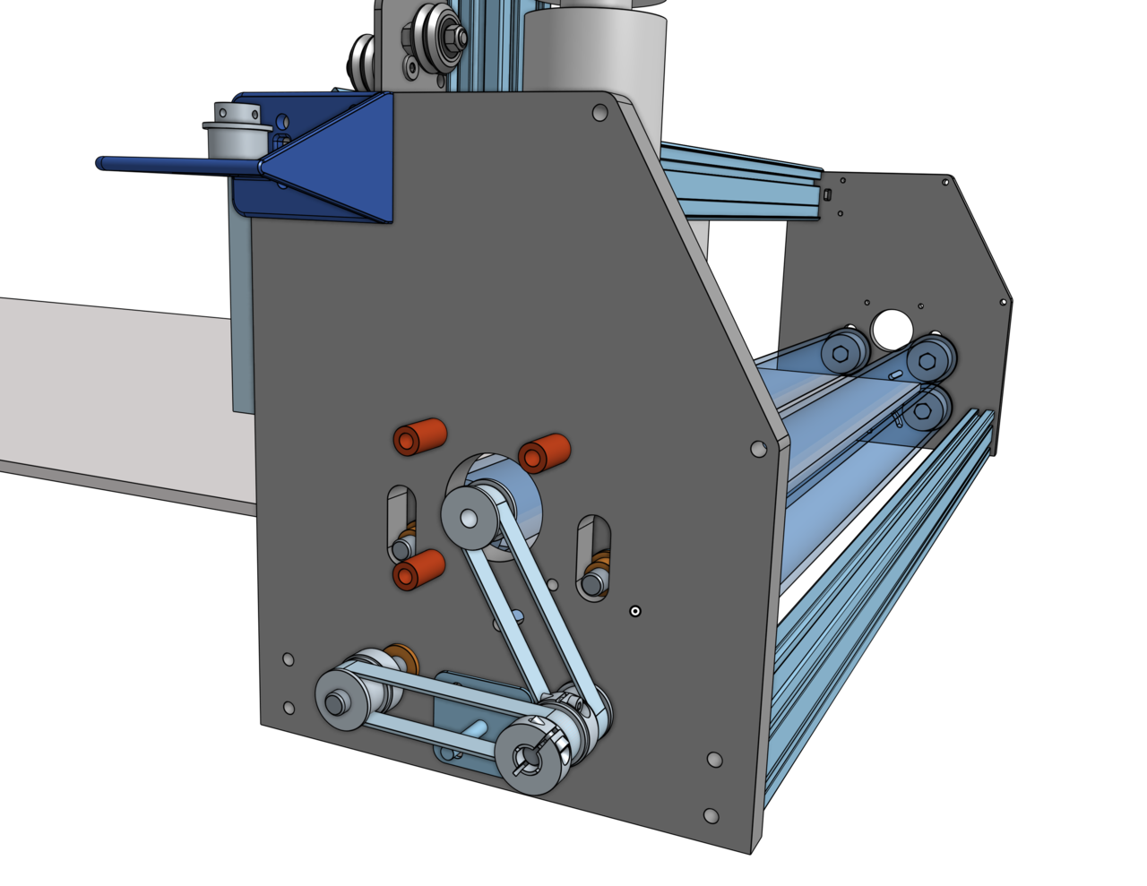
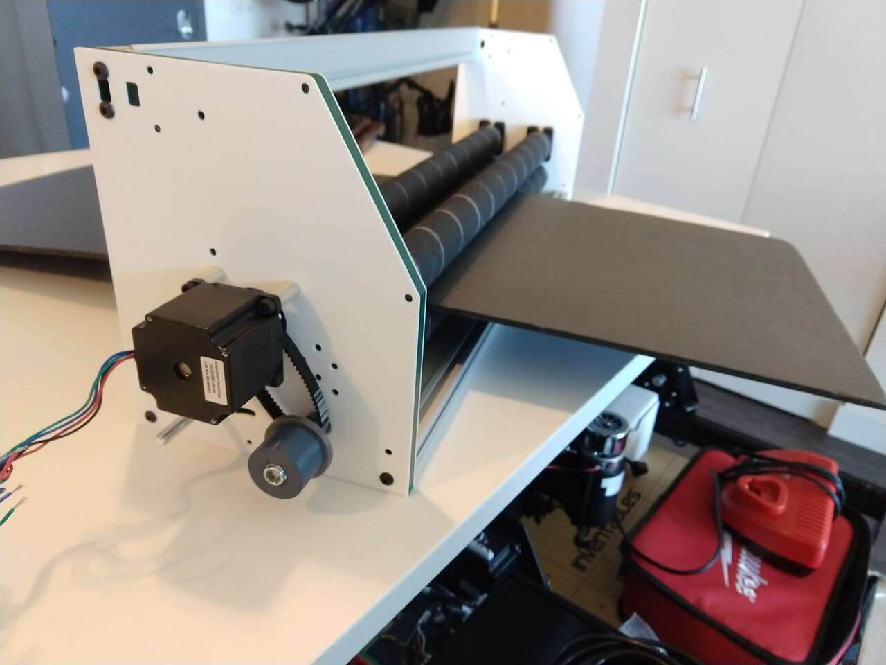
Y-Axis Drive Train
Drive train for Y axis being added. The pulley spacing is perfect putting a slight tension on the belt loop. There is a provision for a tensioner. Eventually I will use a single serpentine belt in a inverted T shape with two idlers to reduce the number of pulleys. This will also bring all pulleys in line with each other.
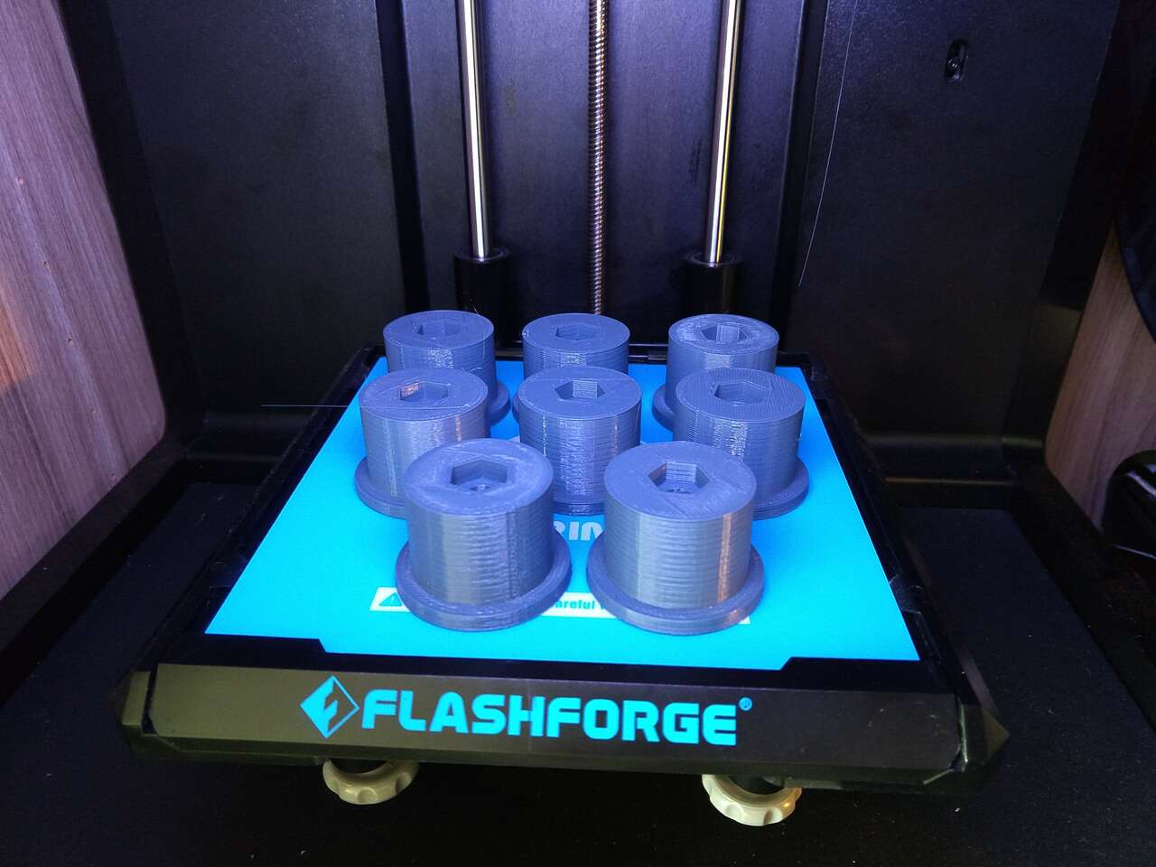
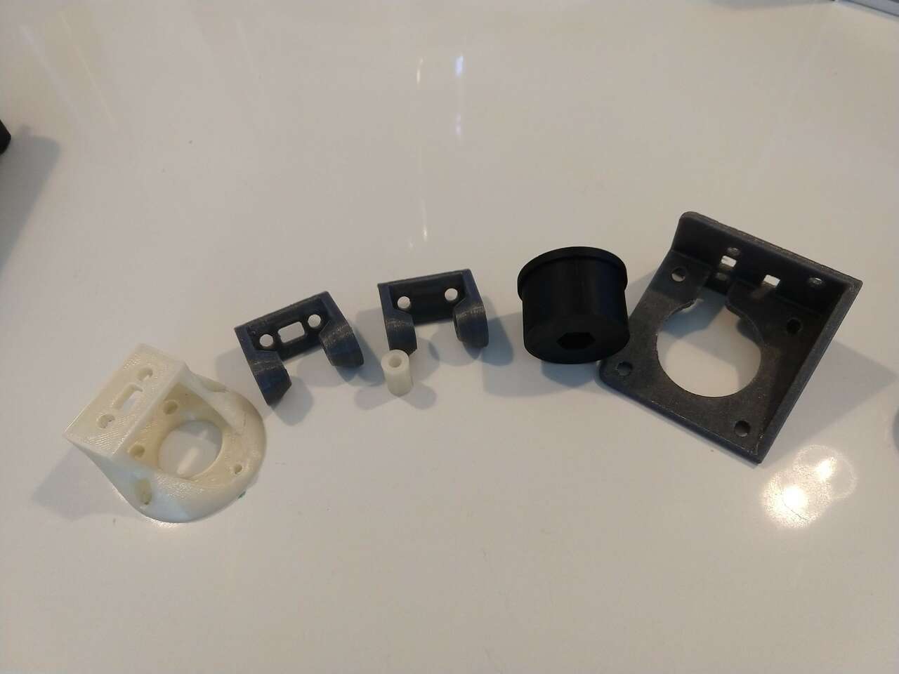 Here are some of the earlier version of 3D printed parts. These have all been replaced by better part designs. I love iteration of complex parts with 3D printing, it allows quick changes in order to improve machine performance. 3D printers are so quiet and pleasant to run next to my CAD CAM work station. Over time I have come to really appreciate the accuracy and exactness of the Prusa MK3S 3D Printer I have here at home.
New Rollers (42 mm Aluminum Conduit)
Realizing that the PVC pipe rollers were bent, I switched over to aluminum conduit for the rollers.
This required re-designing and 3D printing new roller end caps.
I also switched to 8mm ground rods for all shafts, the M8 bolts I had been using initially were not round enough and introduced wobble.
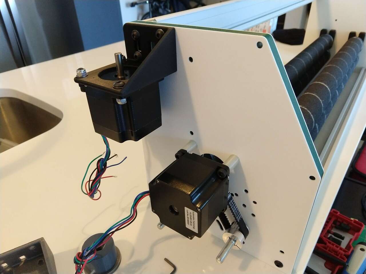
X and Z axis drives complete
As of July 31 my staff is now running our Fab Lab and I am off on Furlough and vacation through Aug 11. I plan to use this time to relax and get the Foam Crawler CNC milling foam sheets. I also plan on presenting the Foam Crawler to Fab Academy on Aug 5 or 12.
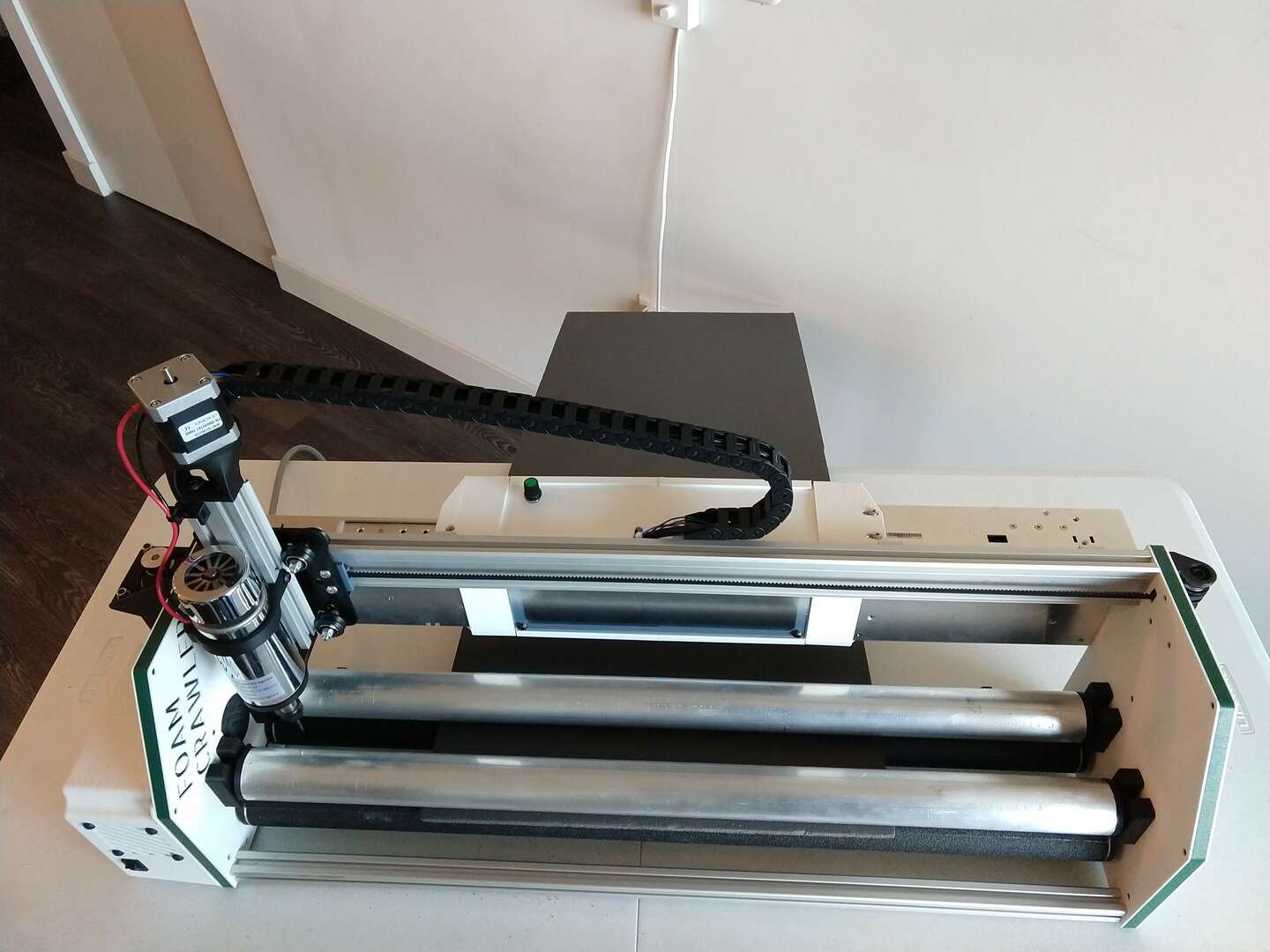
I completed the X and Z axis drives.
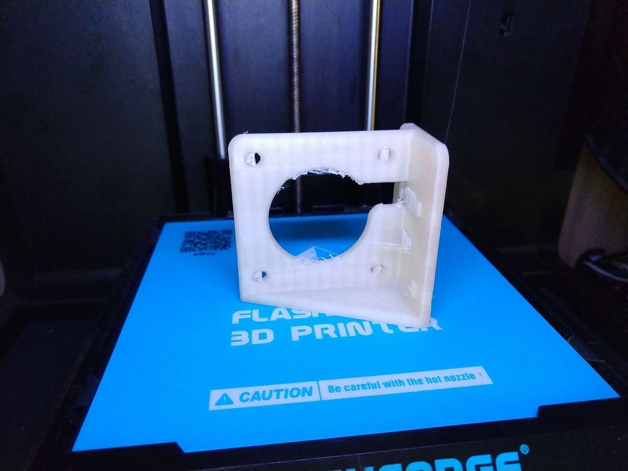
I milled and installed the spindle mount.
3PakCNC Control Board
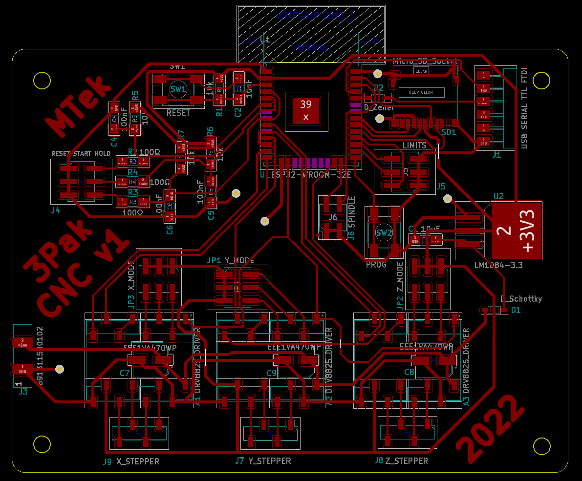
I designed, fabricated, and programmed a ESP32 module based PCB called the 3PakCNC controller tyo run the FoamCrawler. The 3PakCNC control board documentation is so extensive it has it’s own page here:
3PakCNC Control Board project page
Prototype Electronics
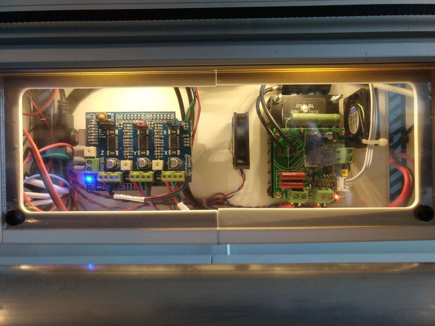
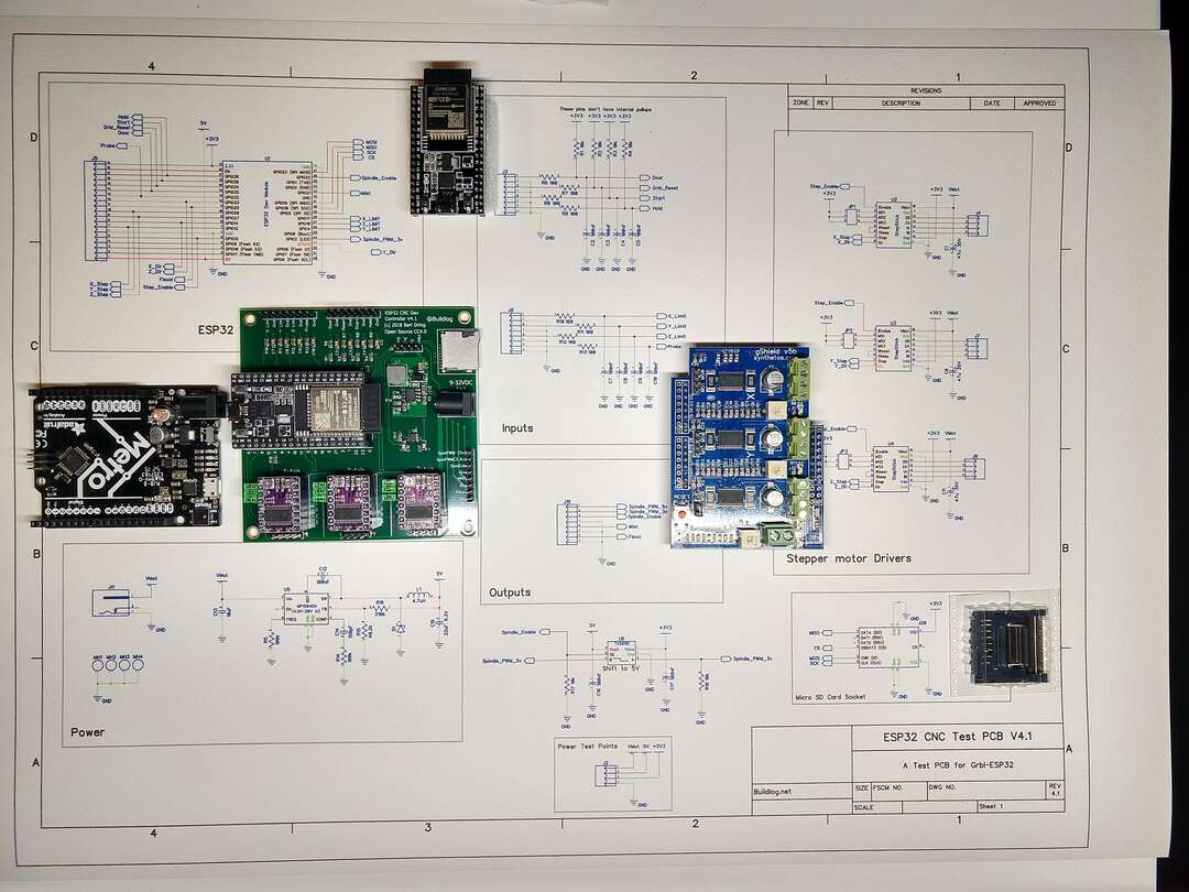
Before I fully completed the 3PakCNC Control Board above I used a off the shelf GRBL sheild and arduino to get the FoamCrawler running.
GRBL gSheild Setup
I have a lot of Synthetos gShield CNC controllers in stock, so that’s what I’ll be using to control the Foam Crawler. The instructions for connecting the gShield I used are here: Using grblShield
I compiled, flashed, programmed and setup the gShield cnc control using grbl.
Installing and getting USB to work with the Arduino IDE on Linux is not well documented. Here is a good post to help: Arduino IDE on Linux Mint
The GRBL wiki has good instructions on how to compile and install GRBL: Grbl wiki!
Universal Gcode Sender(UGS)
To send gcode I decided to use Universal Gcode Sender(UGS) software in the “platform” flavor. The download for linux platform UGS was located at: https://github.com/winder/Universal-G-Code-Sender.
After wiring up my 24VDC power supply, I plugged a USB cable between my computer and the Arduino UNO with gShield.
I fired up UGS and clicked the Port: to select the port the Arduino UNO was on.
Then I clicked the “Machine” and then “Connect”… and GRBL initialized and talked back! YES!
It’s Alive!
I then executed some jog moves, they worked moving my X and Y axis along with lighting up the green lights on the gSheild stepper outputs! Although the movements were very weak. I needed to set my stepper driver currents.
Setting Stepper Currents
I used the procedure on the synthetos/grblShield wiki Setting Motor Current to intially set the stepper motor currents.
Later I will verify the current settings with Vref measurements. This is a good guide on that process: Setting the stepper motor current limit from this page “The gShield (version 5) uses a 0.1 ohm current sense resistor so the formula is Vref = 0.8 * I.
The maximum current the driver chip can deliver with appropriate cooling is 2.5 amps. To use this current value you would set the Vref voltage at (0.8 * 2.5 amps) = 2 volts. This is the theoretical current limit.”
Note: the gSheild stepper driver are limited to 2.5 amps
| Stepper | Multiplier | Target Amps | Vref |
|---|---|---|---|
| NEMA 28 X&Y Axes KL23H251-28-4A | 0.8 | 2.5 A | 2.0 V |
| NEMA 17 Z Axis SM42HT47-1684B | 0.8 | 1.68 A | 1.3 V |
First foam cuts
2020-Aug-8
I joined the students and instructors for the Saturday Fab Academy support session. Pablo was the instructor present and we talked about our final projects. I did some more test jogs of the Foam Crawler. When the feed rate seemed reasonable I loaded a grout removal cutting end mill in the spindle and tried some test cuts for the first time ever. The Foam Crawler cut beautifully and the foam sheet did not get pulled out of the roller! Everyone cheered and clapped, it was one of the best moments of Fab Academy for me, all my years of notes and months of CAD and CAM work on this machine came together in a working machine!
Now onto tweaking the machine to get it to cut accurately and precisely.
Steps per mm
Next I used the GRBL settings calculator to get the correct distance movements. I also found the Norwegian Creations Tutorial: Calibrating Stepper Motor Machines with Belts and Pulleys useful for the roller drive calculations. Grbl v1.1 commands can be found here: (https://github.com/gnea/grbl/wiki/Grbl-v1.1-Commands) I also found the FABLAB León LE-CAR-BIL MACHINE documentation useful.
My steps per mm calculations:
X axis
Steps/rev: 360 deg / Step Angle 1.8Deg = 200 Microsteps: 4 micro steps per step (1/4 step) Belt Pitch: 3mm Pulley Teeth: 20
srev is the number of steps per revolution for the motor fm is the microstepping factor (1, 2, 4, 8 etc.) p is the pitch Nt is the number of teeth on the pulley attached to the motor shaft.
srev * fm / p * Nt 200 * 4 / 3 * 20 = 800 / 60 = 13.333 steps per mm
Y axis
Belt Pitch: 3mm Steps/rev: 360 deg / Step Angle 1.8Deg = 200 Roller Diameter: 42.9mm Microsteps: 4 micro steps per step (1/4 step)
srev is the number of steps per revolution for the motor Nf is the number of teeth on the final (passive) pulley fm is the microstepping factor (1, 2, 4, 8 etc.) Nm is the number of teeth on the motor pulley Dr is the diameter of the roller
srev * Nf * fm / Nm * piDr 200 * 20 * 4 / 20 * (3.14159 * 42.9) = 16000 / 2695.48422 = 5.936 steps per mm
However, as expected, the variable slip vs grip nature of the grip taped Y Axis rollers needed steps per mm adjustment.
Using the helpful info GRBL Steps Per mm – How to Fine Tune Your Settings I re-calibrated.
On a 441.7 mm move the actual cut length was 444.5
Updated Steps/mm = (Current Steps/mm) x (Commanded Travel) / Actual Cut Length
5.936 * 441.7 / 444.5 = 5.899
5.899 Adjusted steps per mm
Z axis
8mm Metric Acme Lead Screw This Tr8*8-2p(4 starts) trapezoidal Lead Screw results in a pitch of 8mm. Pitch of a lead screw is the distance traveled with one revolution. In this case one revolution results in 8mm movement. If you are not sure of a threaded rod pitch simply put a nut on it and rotate it 1 revolution and measure the distance moved.
Z motor (steps/rev): 360 deg / Step Angle 1.8Deg = 200 Z Microsteps: 8 micro steps per step (1/8 step) Z threaded rod pitch (mm): 8 Pulley Teeth: 1 (direct drive)
srev is the number of steps per revolution for the motor fm is the microstepping factor (1, 2, 4, 8 etc.) p is the pitch Nt is the number of teeth on the pulley attached to the motor shaft. For direct drive use 1.
srev * fm / p * Nt 200 * 2 / 8 * 1 = 400 / 8 = 50 steps per mm
| Axis | Steps per mm | Setting Command |
|---|---|---|
| X | 13.333 | $100=13.333 |
| Y | 5.899 | $101=5.899 |
| Z | 50 | $102=50 |
Inverting Axes
The Z axis was inverted, So I issued the following command to Invert Z:
$3=4
Carefully read the documentation at: Grbl v1.1 Configuration:$3 – Direction port invert, mask and you will be able to understand how the code above works.
Max Feed Rates
Jogging the machine was painfully slow. So I updated the following Max rate, mm/min
X $110=8000
Y $111=8000
Z $112=4000
Acceleration
Acceleration could be increased as well
X $120=3000
Y $121=3000
Z $122=200
Turn on and off Steppers
$1=255 turns the stepper motors on indefinitely after making a move holding them in position. This leads to more energy use and hot steppers, but to make sure stuff is not bumped out of position this option is helpful.
$1=25 turns off the stepper motors after 25 milliseconds (default)
For the Foam Crawler, there is significant cutting force applied during cutting and my Z-Axis is low friction I decided to use the $1=255 option.
Max travel
Note: I need to install homing switches and enable homing before this feature will work!
The Foam Crawler has a work envelope of:
X = 610mm
Y = 1220mm (max foam sheet length readily available Y Axis is actually infinite)
Z = 35mm
X $130=610
Y $131=1220
Z $132=35
LED interior Lights and Two-way Mirrors
2020-Aug-13
 5:30am another sunset, another day working on the foam crawler machine.
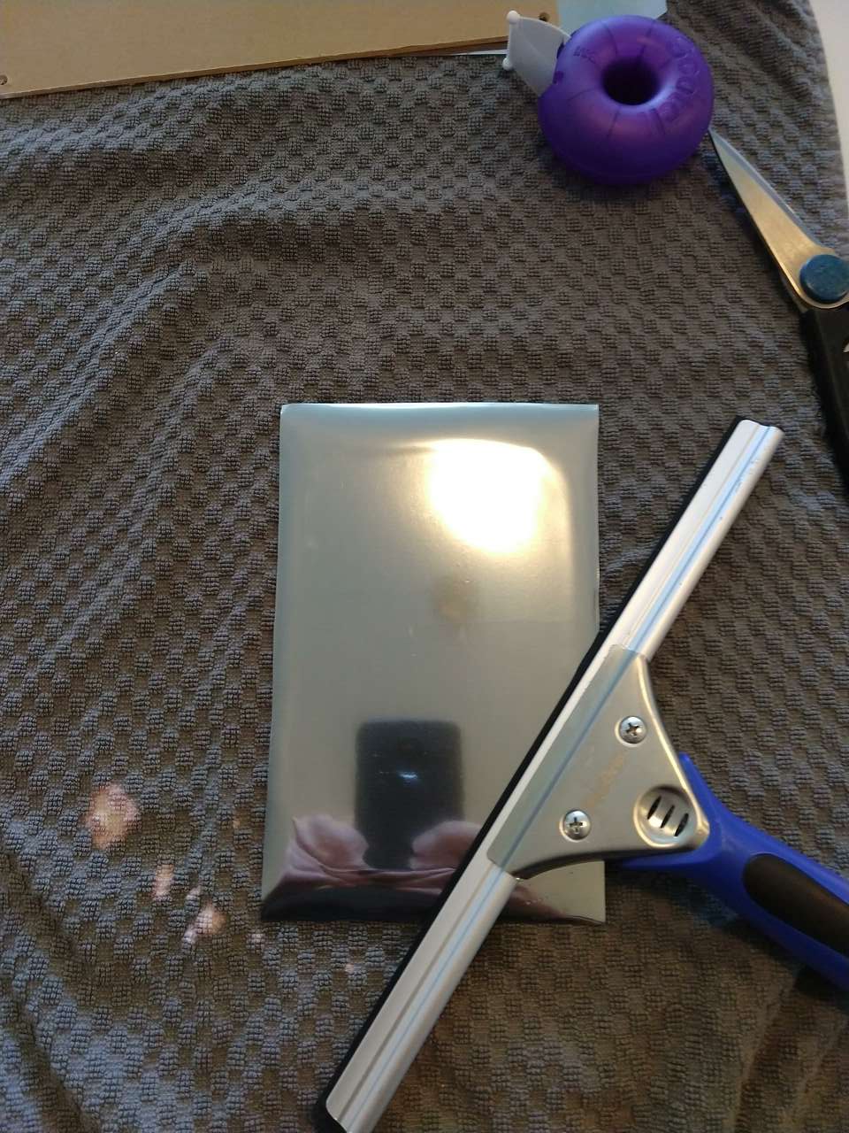
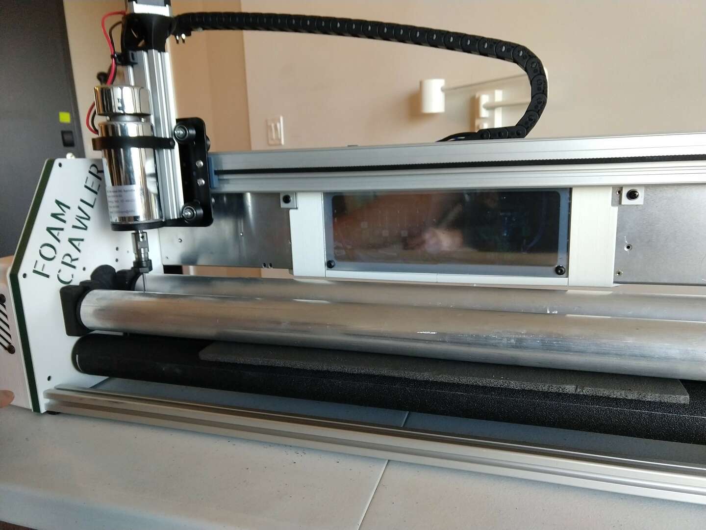
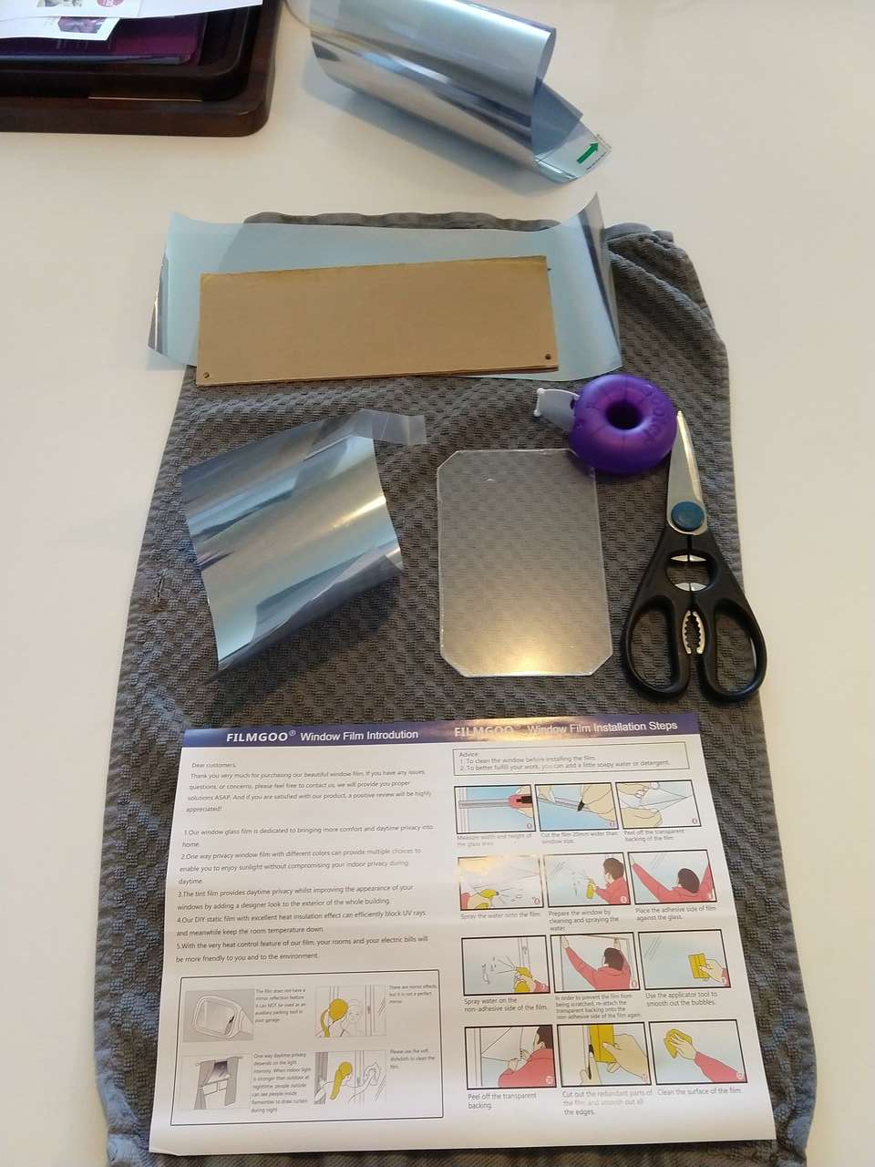 Vinyl 3 way mirror
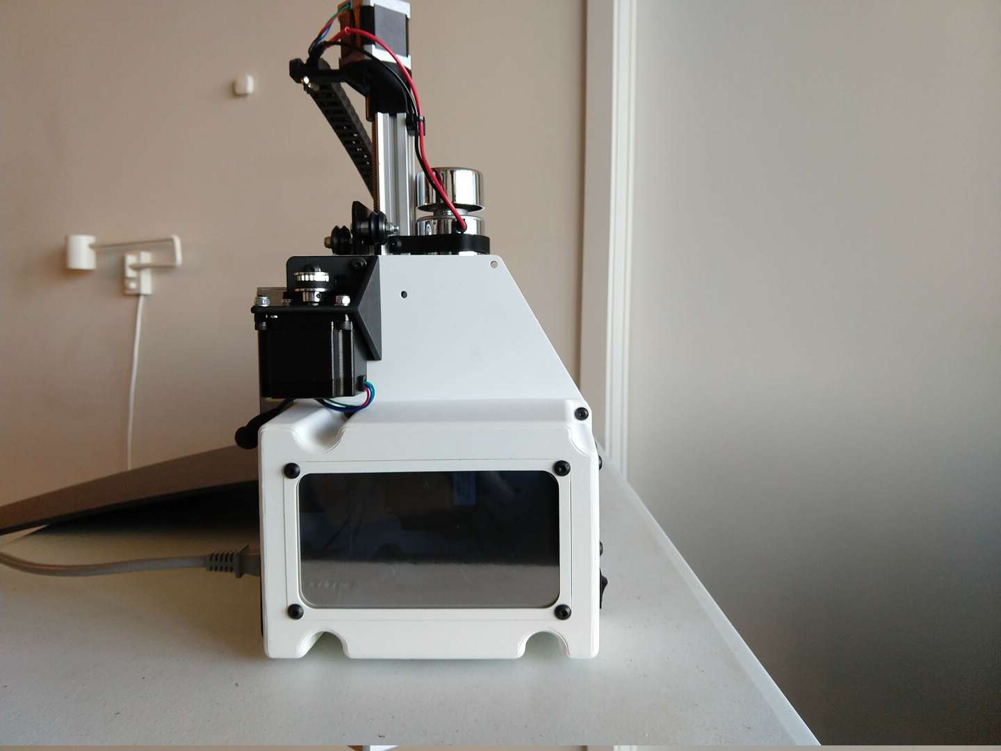
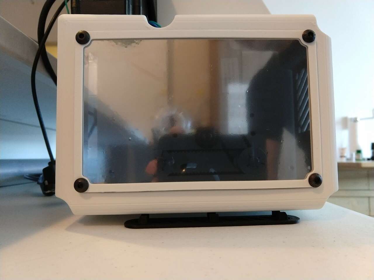 interior case lights off
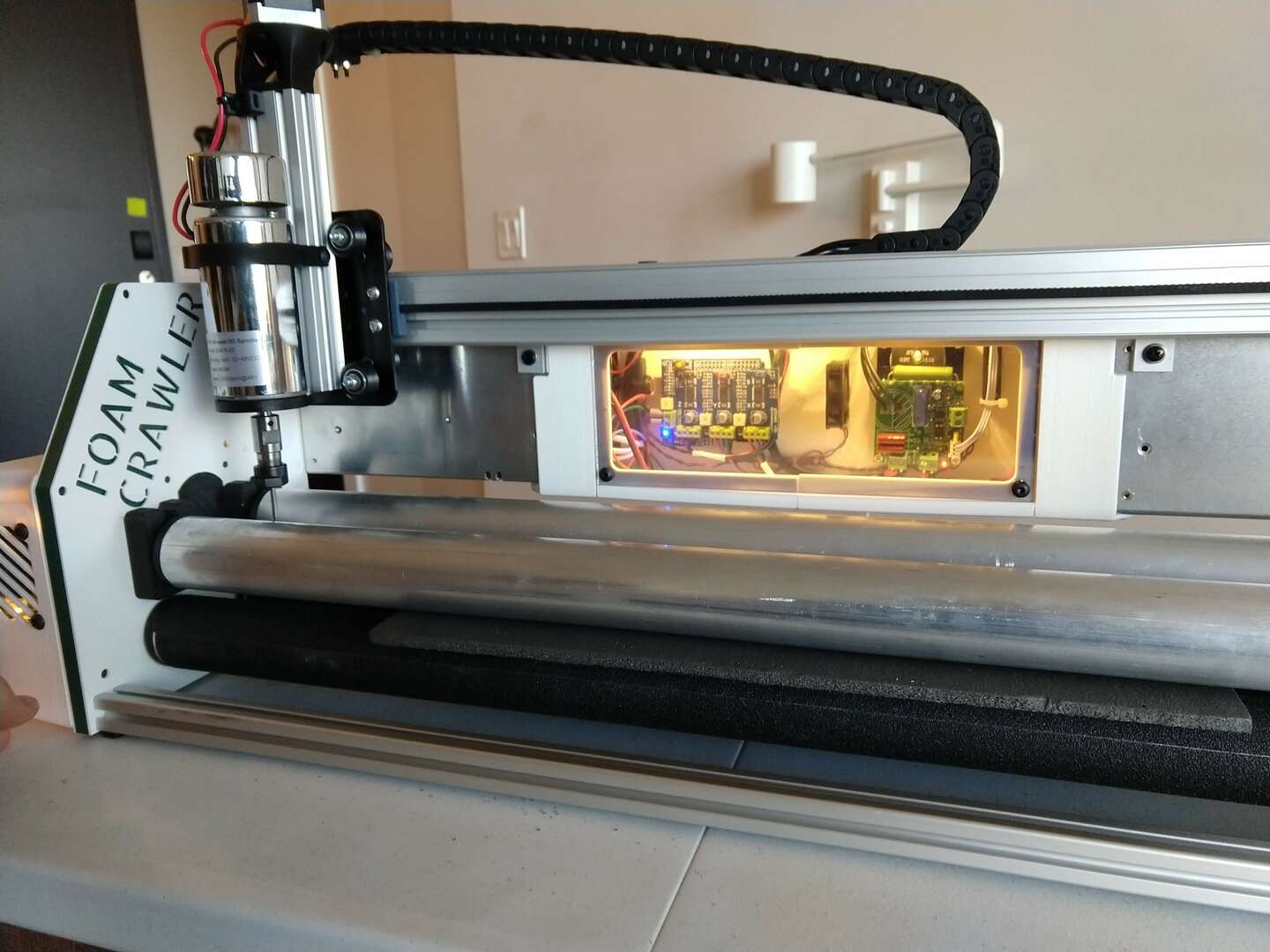
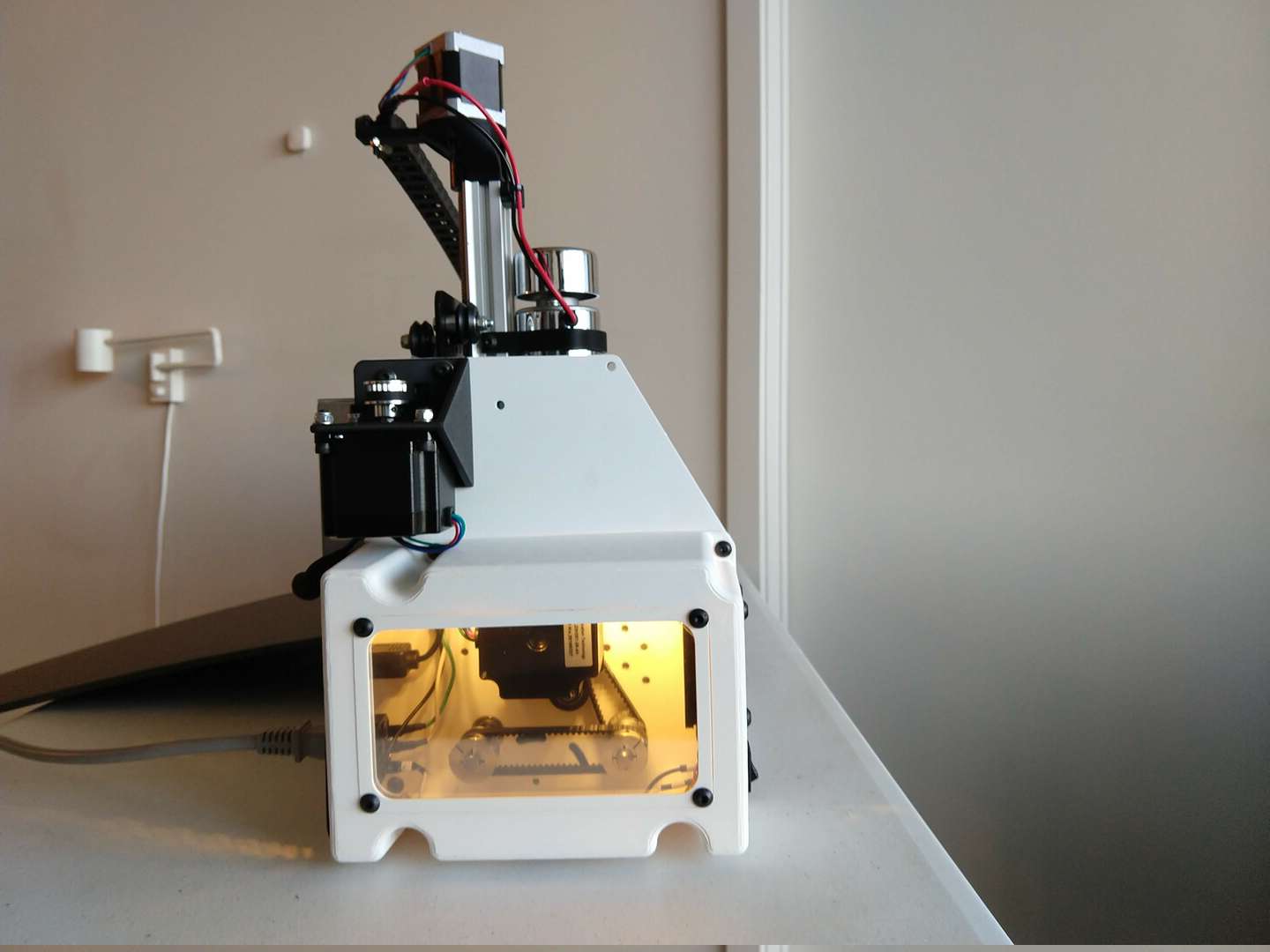
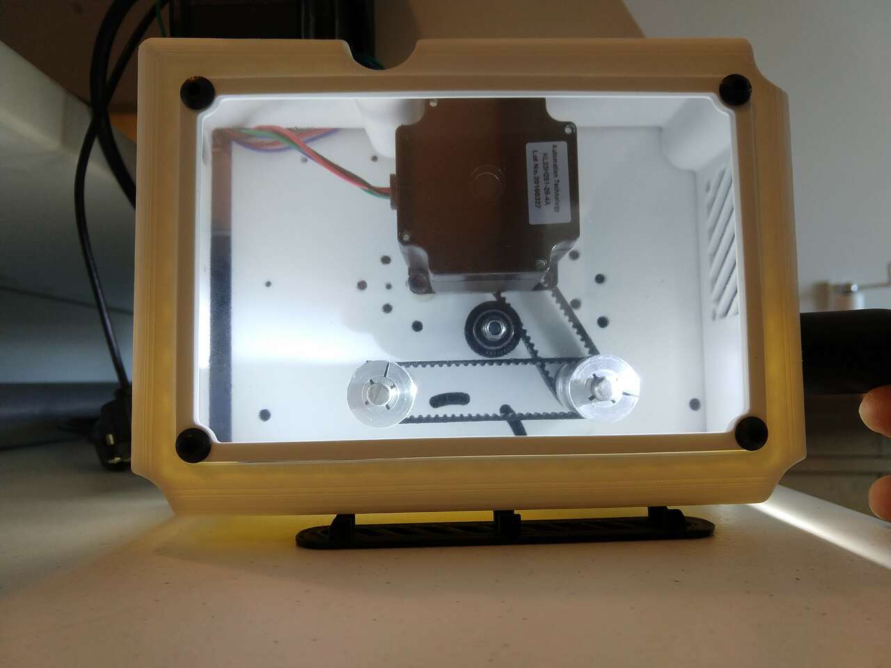 interior case lights on and the workings of the machine are reveled.
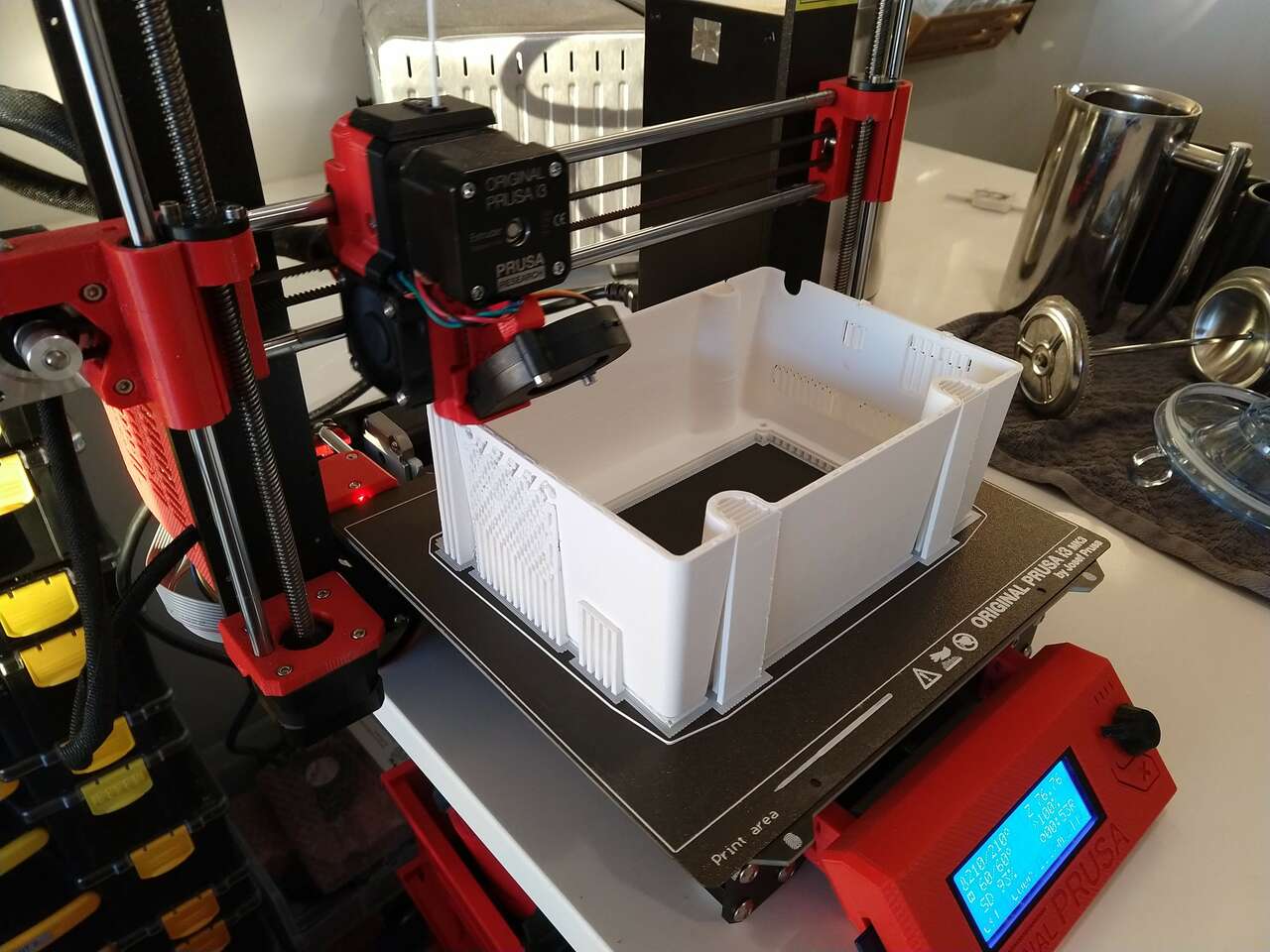
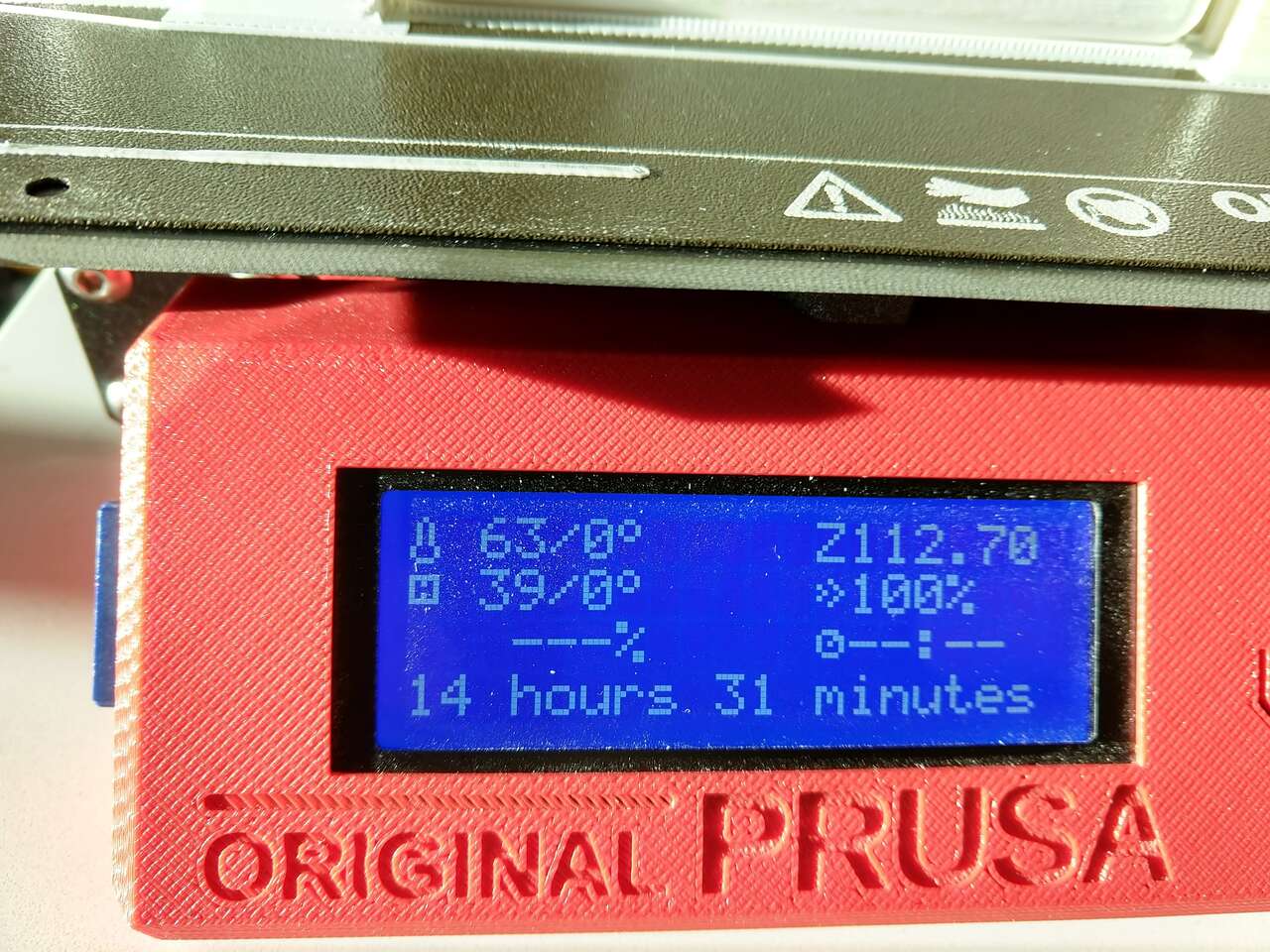 Time for large left side cover print
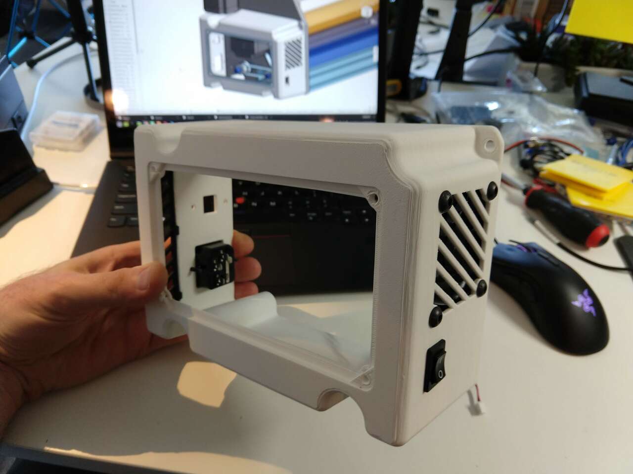 Fans, power, usb and switches mounted
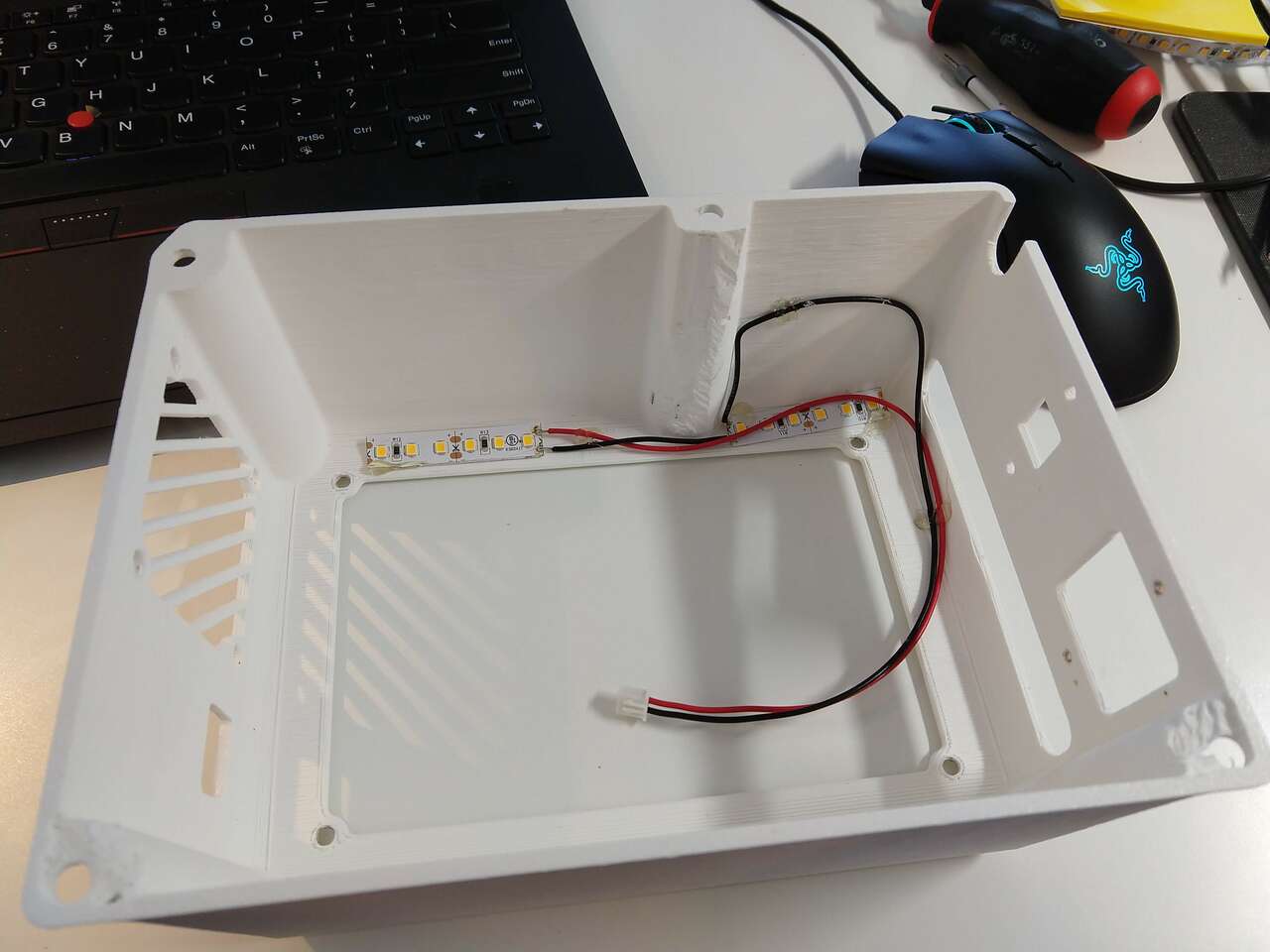
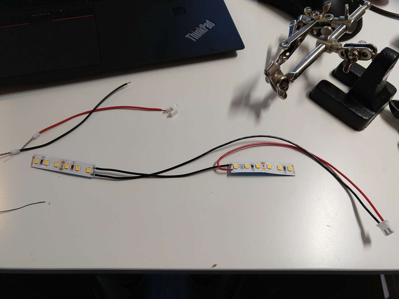 LED’s for interior lighting
 Loading the 1/16 inch diameter dremel grout bit for milling depron foam for my final presentation video.
Final project slide and video complete
2020-Aug-16 I completed my final project slide and video presentation!
Foam Crawler: Video Presentation Foam Crawler: Slide
ESP32 microcontroller board (failed)
2020-Aug-17
Another day and a great sunrise!
 Today I will design a ESP32 microcontroller board that works with my large stock of gShields using kicad. I have named this the: ESP32 to gShield Board. It will be designed in KiCad
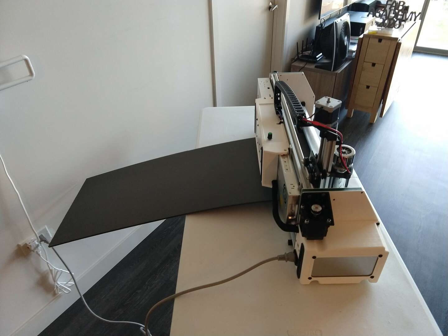
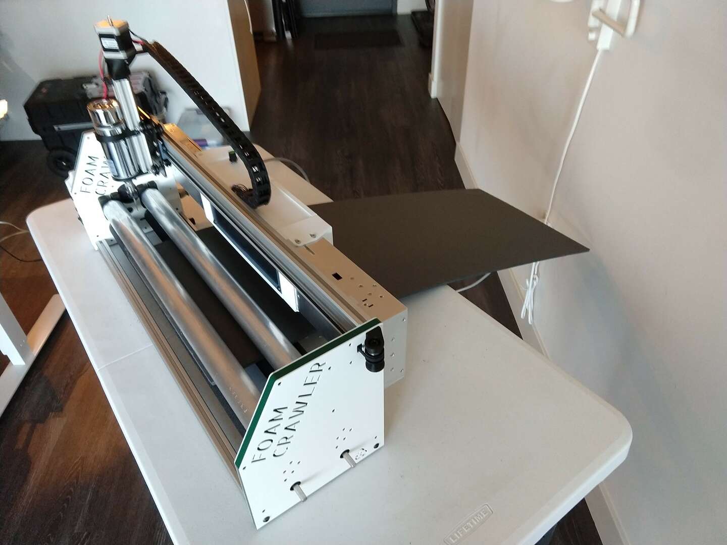
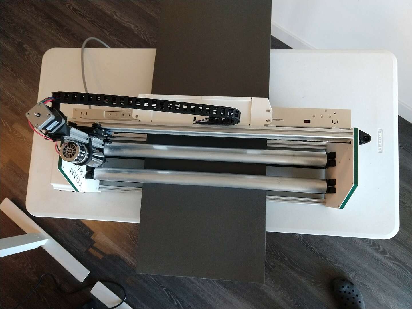
I also decided I needed to take some photos of the Foam Crawler in its fully functional state:
Today I will design a ESP32 microcontroller board that works with my large stock of gShields using kicad. I have named this the: ESP32 to gShield Board. It will be designed in KiCad
I also decided I needed to take some photos of the Foam Crawler in its fully functional state:


Parts delay
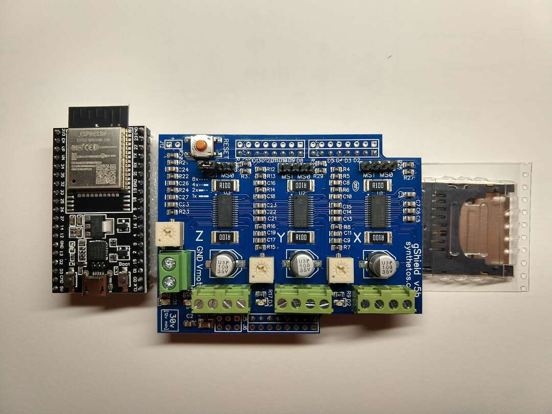
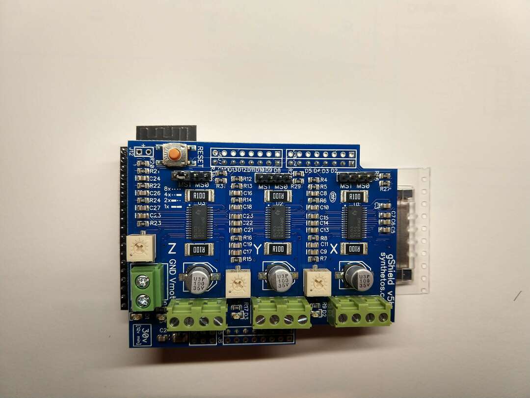
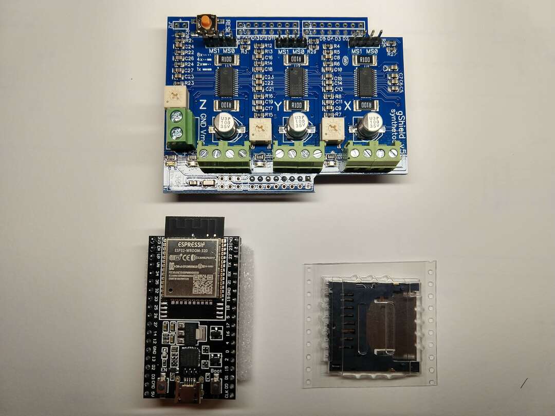
2020-Aug-18 Today I found out my ESP32-WROOM-32D raw chips would not arrive today. This required me to shift gears and design and fab a board that adapts a ESP32-DEVKITC-32D module to my gSheild. I had a lot of trouble finding library symbols for KiCad until I looked carefully at digikeys product page: ESP32-DEVKITC-32D I noticed that they had a EDA / CAD model link under Documents & Media clicking this link brought me to Snap EDA which I needed to create an account for. I did that and then it unlocked a very easy to use download and guide process! I downloaded the symbol and footprint for KiCad as well as CAD 3D model to use in onshape.
I hoped to mill and stuff my ESP32 to gShield Board today, but the process of getting back into KiCad took some time and I will need more time to complete things.
I did find the KiCad tutorials by
Final Presentation
2020-Aug-19
This is my day to present the Foam Crawler as my final project for Fab Academy 2020.
 Sunrise!
I presented the Foam Crawler to Neil and all my fellow Fab Academy instructors and students!
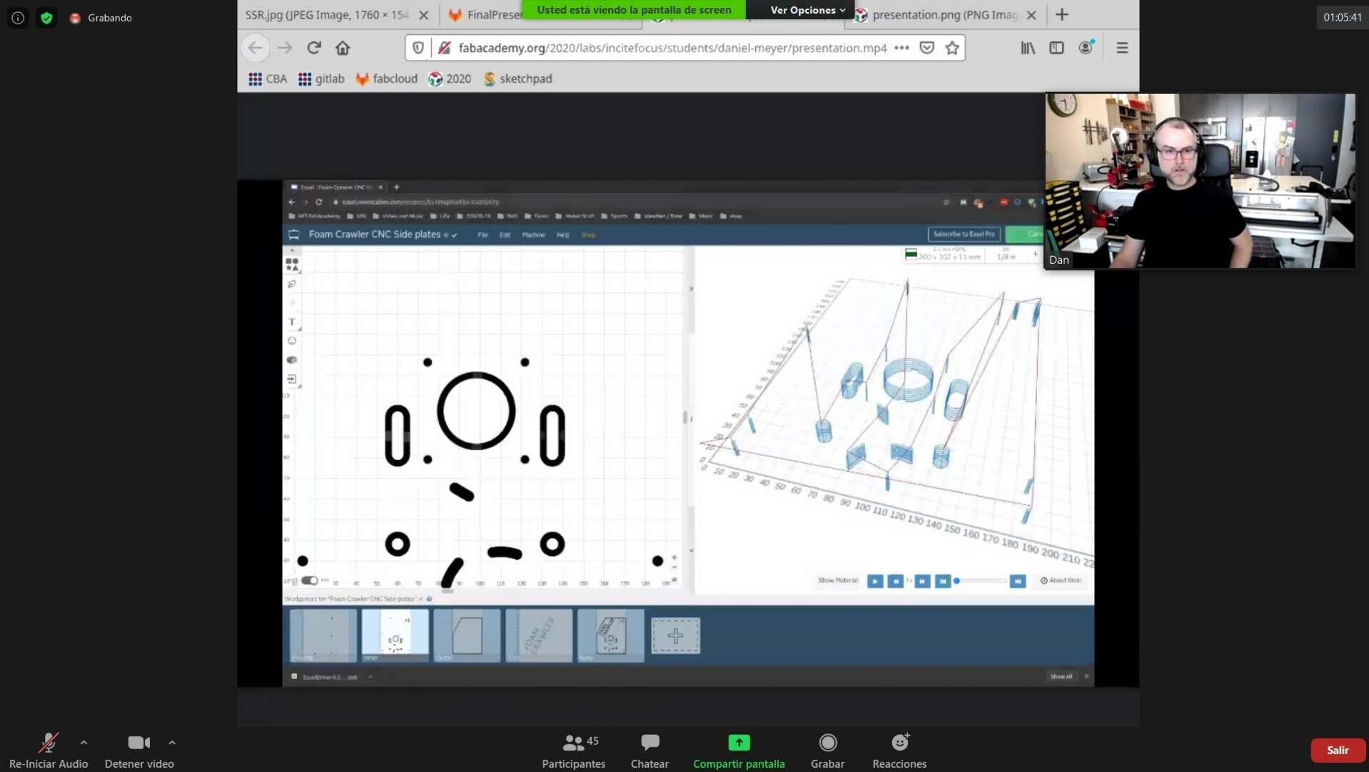
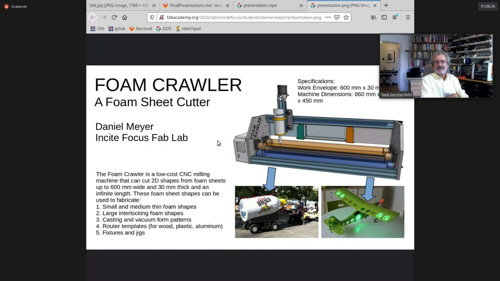 Above are some screen captures made by Adrián Torres of the presentation.
Final Presentation Video, to all Fab Acadaemy 2020 Includes discussion with Neil on what additional parts I need to complete for my Final project to pass.
Presentation Action Items:
To graduate complete:
- Neil: Finish custom control board using raw microcontroller chip.
On the 4th of July 2022 I complete the above task! I designed, favbricated, and programmed a 3 axis cnc control board for the foam crawler, called the 3PakCNC Control Board. Here is the link to the documentation:
3PakCNC Control Board assignment page
Stretch goals (for additional development spirals)
- Neil: Add vibration exacto knife tool head per Jon Ward / OtherMachine work
- Contact Rico in Japan, he wants to build and Foam Crawler for his fab lab in Japan.
- Neil: try cutting nice thick strong cardboard from u-line.
DanDuino (Simple)
A simple milled Arduino Uno clone that connects to a gShield v5b. To keep it simple the early version of this board will run off of 5vdc via USB. However it would be great if later versions could run off of a DC to DC converter taking 24-48VDC input and outputting 5VDC.
ChiDuinoESP microcontroller (Complex)
Here are some layout concepts for in process ChiDuinoESP microcontroller that I will use in the Foam Crawler ESP:
Feedback
from Nadya Peek
- FoamCrawler is awesome!
- like the form factor
- material rollers are great
- reminded of the othercutter
- mirrored acrylic is also extremely cool
- interface and interaction design: One thing that I think often gets overlooked during machine building is the actual interface and interaction design for using the tool. E.g. how does it help you load the material? Zero the tool? Make toolpaths? Can you make that more friendly and playful? Who might the users of the machine be, and what does friendly mean to them? What are e.g. ways they might want to do CAM?
- replicability of the work: These days with machine design one thing I’m really trying to push on is figuring out how to make it possible for others to build their own machines. The Jubilee project (jubilee3d.com) has been pretty successful in that regard, where people who aren’t working with us directly are still able to build their own.
- Part of the replicability relies on the documentation, especially the documentation of the electronics. We’re using a Duet, but some other community members are also extending to Klipper. Another group wants to use a teensy, and is porting GRBL to the teensy. I totally understand the appeal of surplussed motor driver boards, but is there a way you can document the work such that other people who will source parts differently can also build it?
My thoughts based on Nadya’s Feedback
- FoamCrawler is awesome! Thanks!
- like the form factor Yay! The narrow depth of the machine is awesome!
- Rollers I like the rollers too, but they have been difficult to get to position the material with my preferred repeatability. The rollers do slip at medium and high cutting speeds, so I just slow down for now. I am seriously considering bringing back my rack or tank drive ideas to index the material along the Y axis in a repeatable way at high speeds and cutting forces. A rack drive would also allow the foam crawler to cut harder materials.
- Other Cutter The other cutter vibrating hobby blade is genius and I would like to have the option to mount that style cutter in the Foam Crawler. The most likely candidate right now is this MATRIX™ Jigsaw Attachment. The code needed to rotate the back the cutter up is a bit freaky to me, but Jon Ward offered to help on that front, so it’s much less freaky.
- two way mirror film Cool! All my machines are going to feature two way mirror film for revealing innards in the future! Everyone loves the reveal of the machine guts when I power on the internal lights!
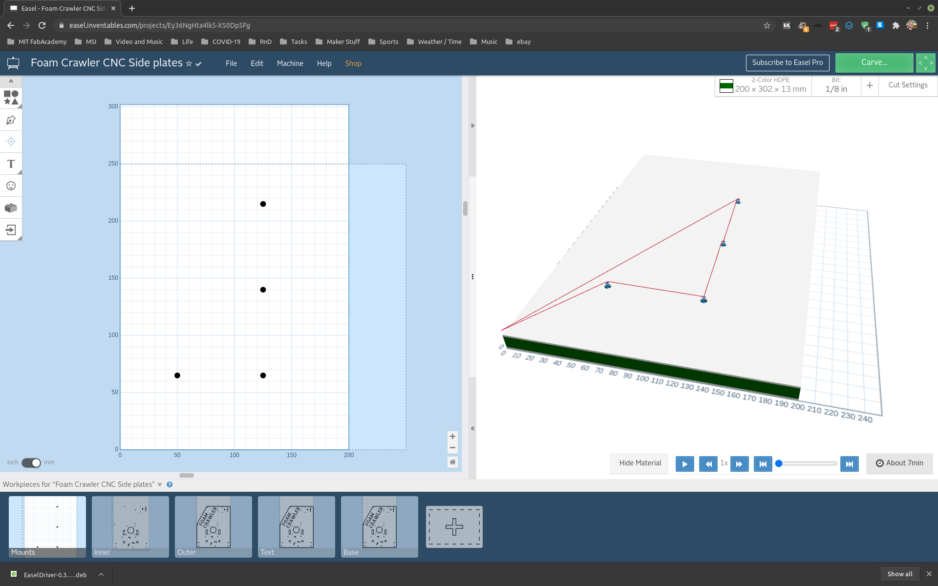
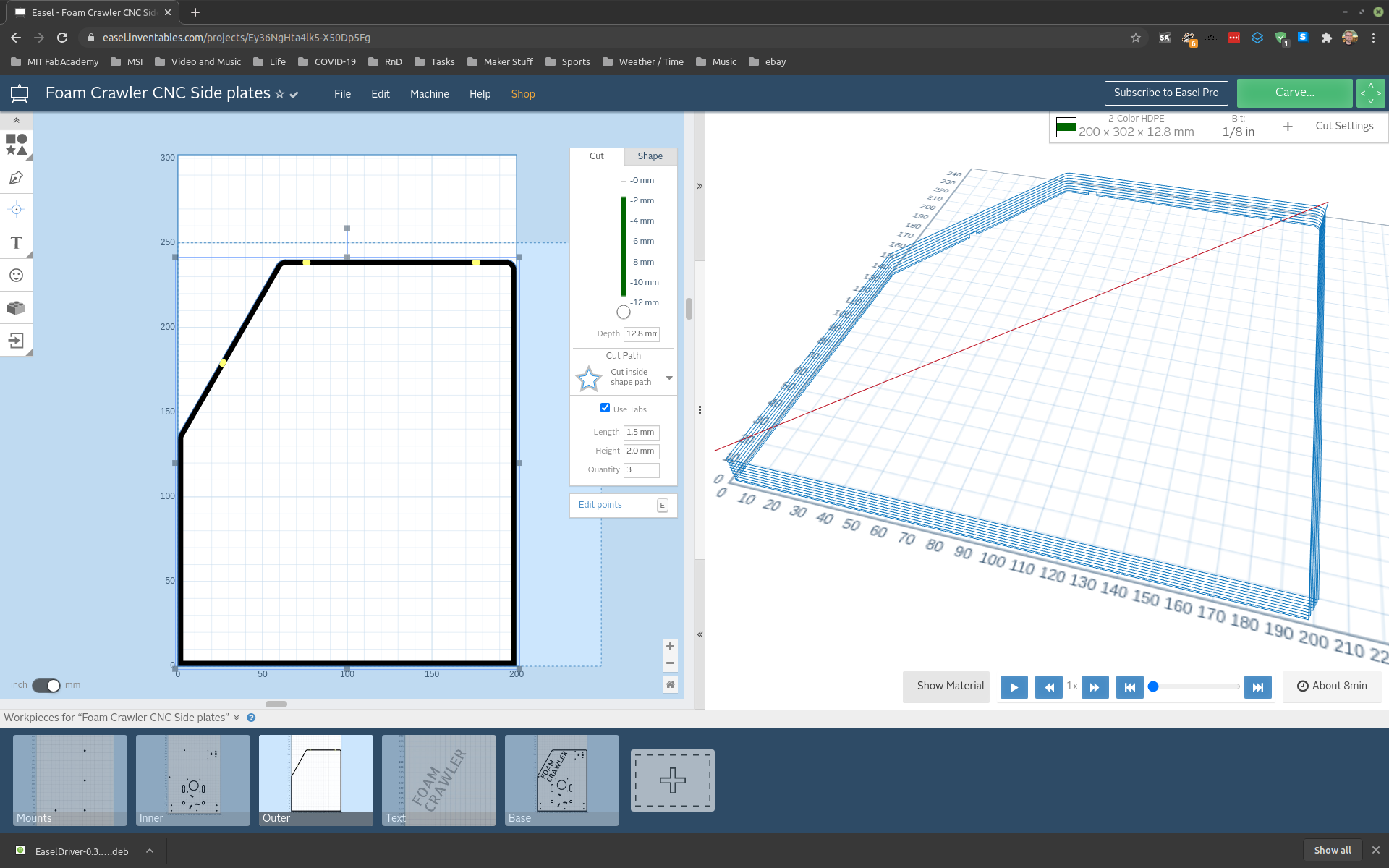
- Interface and interaction design: should be friendly and playful. I can’t agree more. I dream of creating a process flow that’s simple and logical to normal humans to mill sheet materials. I feel like we are stuck in the traditional industrial education method of setting up milling machines that we have been teaching machinists, like me, for way too long! I would like to add a low cost touch screen interface with easy to follow prompts guiding semi automatic loading of sheet material using limit switches, IR sensors. or conductive sensors. Z axis homing could be done with a small piece of copper or aluminum tape folded on the corner of the sheet material utilizing conductivity with the tool bit for x, y and z homing. Running jobs off a usb thumb drive using a touch screen would free the machine up from a constant computer connection. Right now the easiest to use design software to layout cut files for the Foam Crawler is Easel by Inventables (free version works well). However it dives me mad that it’s so much more difficult to generate cutting code for a milling style machine like the Foam Crawler compared to running a 3D Printer. Tabs are the most time consuming for complex geometry, for simple geometry auto tabs do work quite well.
- Replicability of the work: This is very important, and if the Foam Crawler is not easy to use people won’t be motivated to build and use it to make their foam objects real. The process from idea, to cad design, to cam, to running the machine should be a enjoyable and and fun. My Fab Shop Workshops would help massively with the replicability of the foam crawler locally in Chicago and possibly online with streamed builds. This site itself is the start of documentation, but way more is needed to help others build Foam Crawlers. Many of the Foam Crawler cad design choices were made with ease of user assembly and fabrication in mind. Combining multiple features into one 3d printed part was very powerful. The HDPE plates ended up being much simpler to cut and assemble then I imagined. The first and second humans to build a Foam Crawler via Fab Shop Workshops will drive documentation for replicability of Foam Crawlers in the future.
- Replicability of electronics: The electronics are very important to be reproducible, and I like to do that within a tight budget. I think that ESP32 Microcontroller Board running GRBL is the way to go. The ESP32 Microcontroller Board selected should be open source and be reproducible in a fab lab from scratch or purchasable off the shelf. I think the Grbl_ESP32 CNC Development Board by Bart Dring (who lives in Chicago) is the best option. For touchscreen control and sending g-code via thumb drive I think a MKS-TFT touchscreen running GRBL firmware would work well. A MKS-TFT touchscreen costs between $20 and $40. I found a guide for setting up these touchscreens with GRBL firmware a few months ago: GRBL firmware on MKS TFT32 TFT28 TFT24 New life for old 3D printer LCD display MKS DLC 2.0
Feedback from Jens Dyvik
Try using a compression milling cutter to cut cardboard.
Historical Concept Sketches
Mainly Idea, Study, and Prescriptive Sketches. I use these sketches just before and during CAD. My sketch repository: Foam Crawler CNC Machine Sketches
Notebook 2D Sketches
I do a lot of 2D Sketching in planning to make a physical object or mod an existing object. I record many of these sketches digitally, but I am going capture, and better organize and document these sketches on this site going forward.
The IDSA has a great article on the different types of sketch techniques and step to a final production product used: https://www.idsa.org/education/how-they-do-it
FutureMods
- Rack Drive Platen Design a Corrugated Cardboard and or Corrugated plastic carrier board, driven by flanged pinions on the left edge of rollers and un-flanged wide pinion on right edge of rollers. Integrate pinions into roller end plugs. The platen will allow exact Y axis drive with math, rather than variable factor with grip tape drive. Grip tape will be removed and back of platen will ride on raw aluminum conduit, supporting down force of peck milling moves. Flutes of cardboard will be in the y direction, allowing conforming and compliance and bending along X axis (why this may be useful I am not sure). A platen will allow for removable tack spray to be applied to a Corrugated plastic platen to mill squishy EVA foams for cos-play costumes and other fabrication. Corrugated platen will most likely be A or C flute
- ESP32 Microcontroller Board Design and fabricate a board based on the ESP32 to replace the Arduino UNO. The new ESP32 board will work with the large stock of gShields I have in stock that should not be wasted.
- Wall Edge Mount Change the orientation of the Foam Crawler to run hanging from the wall or over the edge of a table. This would allow chips and dust to fall out the front of the machine as well as allow the machine to be run in limited space. Springs or 90 degree counter weights would most likely need to be added to the upper rollers to hold materials against platen or lower rollers in this configuration.
- Roller Springs Add springs to apply clamp force to upper rollers. This would allow the machine to be mounted on a wall to run in limited space. This also allows for increased force on the rollers over gravity force used currently.
- Try blue ray laser shark module in place of spindle for lasering foam! Per Dr. Evil “You know, I have one simple request. And that is to have sharks with frickin’ laser beams attached to their heads!”
- Size timing pulleys to optimize stepper motor power curve.
- serpentine drive Add single belt serpentine drive to compact and simplify the drive train.
- Machine Explainer Add Machine Explainer Circuit. An ESP 8266 microcontroller board that turns on lights and indicators based on sensors sensing the movements of the machine. Helps clarify complex machines for museum guests (patrons) during workshops.
- More notes?
Completed Mods
- Add first surface mirror to side cover. Turn on lights inside to reveal the inner workings. Completed 2020 Aug 13
- Removable front upper roller. Shorten roller and add 3d printed U shaped holders to drop roller into for running and out for easy tool bit changes zeroing etc.
- Add 3D Printed conformal organic shaped drive train covers
Inspiration
PhlatPrinter MK1 by Mark and Trish Carew MTM Snap by: Jon Ward & Nadya Peek Pop-Fab by: Iian Moyer & Nadya Peek Fold-a-Rap by: Emmanuel Gilloz and the FoldaRap team littlerascal by Jake Read
References
- Core Crawler CNC Prototype 1 Google Photo Album
- HDPE Recycling symbol used on side plates.
CAD files
See this link forOnshape CAD files of the Foam Crawler Assembly: FoamCrawler CNC
Exploded View and Bill of Materials
Use this PDF of a exploded view of the foam crawler with Bill of Materials (BOM) to help assemble a Foam Crawler core. Foam Crawler Core Exploded View & BOM
License
Everything on my Fab Academy site is licensed under the Attribution-ShareAlike 4.0 International license. To see what this means click this link: Attribution-ShareAlike 4.0 International (CC BY-SA 4.0)

This work is licensed under a Creative Commons Attribution-ShareAlike 4.0 International License.
One exception are a few projects that I specifically labled as released into the public domain. These are projects that benfit society directly, especailly during the COVID-19 pandemic.
2020 vs 2022
In 2020 I presented the Foam Crawler with an off the shelf control board. In 2022 I presented the Foam Crawler with my cutom designed and fabricated 3Pak CNC control board to meet the final project requirements.
In 2022 presented the FoamCrawler