6. 3D Scanning and printing
Group Assignment
Link to our group assignment work
| Have you? | Done |
|---|---|
| Group assignment: | ⬇ |
| Test the design rules for your printer(s) | Yes |
| Document your work and explain what are the limits of your printer(s) (in a group or individually) | Yes |
Individual Assignment
| Have you? | Done |
|---|---|
| Design and 3D print an object (small, few cm3, limited by printer time) that could not be easily made subtractively | Yes |
| 3D scan an object, try to prepare it for printing (and optionally print it) | Yes |
Checklist
| Have you? | Done |
|---|---|
| Linked to the group assignment page | Yes |
| Explained what you learned from testing the 3D printers | Yes |
| Documented how you designed and made your object and explained why it could not be easily made subtractively | Yes |
| Documented how you scanned and prepared an object (for 3D printing) | Yes |
| Included your original design files for 3D printing (both CAD and common format for 3D printing) | Yes |
| Included your hero shots | Yes |
| Learning | Learned |
|---|---|
| Identify the advantages and limitations of 3D printing | Yes |
| Apply design methods and production processes to show your understanding of 3D printing | Yes |
| Demonstrate how scanning technology can be used to digitize object(s) | Yes |
Design Rules STL Test File List
Design Rules for our 3D printers Print a series of test objects on the different 3D printers we have to characterize them:
| Design Rule Test | Layer Height |
|---|---|
| Nozzle Orifice | 0.4 mm |
| supported overhang | 0.3 mm |
| supported clearance | 0.3 mm |
| angle | 0.3 mm |
| overhang | 0.3 mm |
| bridging | 0.3 mm |
| wall thickness | 0.3 mm |
| dimensions | 0.3 mm |
| anisotropy | 0.3 mm |
| surface finish | 0.3 mm |
Why 0.3 mm layer heights
I 3D print almost all my parts at 0.3 mm layer thicknesses with a 0.4 mm nozzle orifice size. Most part designs do not require thinner layers, thicker layers speed up printing time. Extruder jams are less frequent as well. This also allows for a larger part to be 3D printed given the same printing time. We teach our students at the MSI Fab Lab to consider the amount of time they have to print their design and optimize for that time, this usually results in larger scaled prints at 0.3 mm layer height.
ORD Bot Hadron 3D Printer Design Rules Results
I used 1.75mm RepRapper white PLA filament running at 200deg C. Cura was used as a slicer with 0.30mm layer heights. Nozzle orifice was 0.4 mm. The nozzle system is a bowden fed open source hardware E3D Chimera with a Prusa MK3S part cooling fan and duct.


The ORD Bot does a good printing overhangs with support, the support was removed easily and cleanly.

The ORD Bot can print functional clearance gaps up to 0.3mm at 0.2mm the gap fuses shut.

ORD Bot overhangs are clean up to an angle of 30 degrees. 20 degrees has some drooping. 10 degrees is very droopy.

ORD Bot can do 90 degree overhangs of 1mm wide, at 2mm wide drooping starts immediately. At 3mm drooping is quite severe. at 4mm a significant amount of the feature is lost to drooping.
The ORD Bot is very good at bridging, the video above shows the bridging results.

The ORD Bot can print at .3mm layer heights: .5mm thick walls and .3mm thick slots.
For the dimension test the inner square opening measures 9.6 to 9.75mm with a digital calipers. The outer square dimension measures 20.25 to 20.3mm. These undersized and oversize characteristics can be informative during the design process.

I don’t see many artifacts in the anisotropy test.


The surface finish test looks pretty good considering the 0.30mm layer heights.
Conclusion: Design Rules results
The ORD Bot shocked me with the quality it could produce. My ORD Bot is somewhat of a Frankenstein DIY 3D printer, using whatever parts I could afford and was interested in at any given time added to it. My ORD Bot is quite old with its first successful prints in 2012 after several failed attempts in 2011 shortly after being built.
I now understand the limitations of my ORD Bot running PLA with 0.3 layer heights. Most test prints limitations seemed to be related to the 0.3mm layer height and not the ORD Bot mechanics. Most important to me is the dimension test verifies that at 0.3 mm layer heights: 1. A 0.3mm max oversize condition is present on outside dimensions. 2. A 0.4 max oversize condition is present on inside dimensions.
These clearances verify why I find a 0.3 to 0.6mm clearance to work well on parts that slip together with minimal to no effort.
Here is a summary chart of the results with the max value that is acceptable for my 3D printing expectations:
| Design Rule Test | Max Value or Pass/Fail |
|---|---|
| supported overhang | Pass |
| supported clearance | 0.3 mm |
| angle | 30 deg |
| overhang | 1mm |
| bridging | 20 mm |
| wall thickness | 0.5mm walls, 0.3 mm slots |
| dimensions | 0.3 mm outside swell; 0.4 inside swell |
| anisotropy | minimal artifacts |
| surface finish | 4th layer of sphere apex |
Individual assignments:
Design pro-additive object
The goal is to design an object that could not be easily made subtractively. Or to design a part that takes advantage of additive nature of 3D printing. This means features that are undercut, blind, and nested should be used. Using the ORD Bot 3D printer I should be able to design nested parts that free up after printing if they have a clearance gaps of at least 0.3mm, 0.4mm gaps would be very safe.
3D print pro-additive object

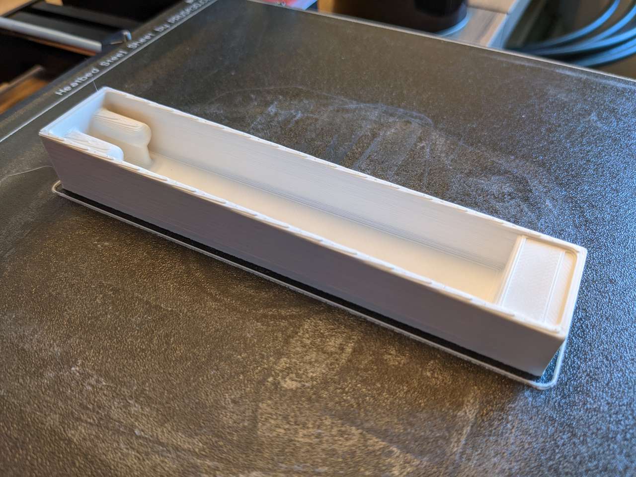
This model I design has quite a few undercuts and blind features. Since 3D Printing allows me to make these features I don’t have to be constrained as I would be with milling and molding processes. I also designed my part with ribs to strengthen the part, and eliminate the need for supports.
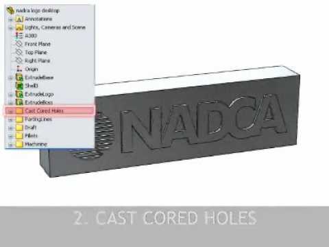
Comparison to Die Casting Design Process
I also added fillets, ribs and other features that will strengthen the part. Interestingly many of the features that optimize a design for 3D Printing work well for another additive process I am an process and design expert in, Die Casting. See this Die Casting Design website https://www.diecastingdesign.org/videos/design for the videos I created on this topic
of specific usefulness for 3D Printing are these video:

Pro-additive CAD Steps

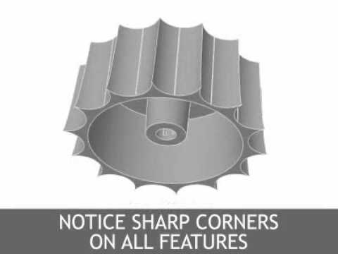
Next I used draft analysis of 3 degrees to visualize undercuts and blind features. Draft analysis is available in all major CAD packages and is a powerful tool when designing for additive and subtractive manufacturing processes.

These first two images show the undercuts present in the orientation the part will be 3D printed in. The two holes at the bottom of the part, in this view, will be clearance holes for M5 screws

The two holes at the bottom of the part, in this view, will be drilled and tapped with a M5 thread.

The image above shows the undercuts if the part were printed with the blue surface on the build plate.
3D Printing pro-additive object
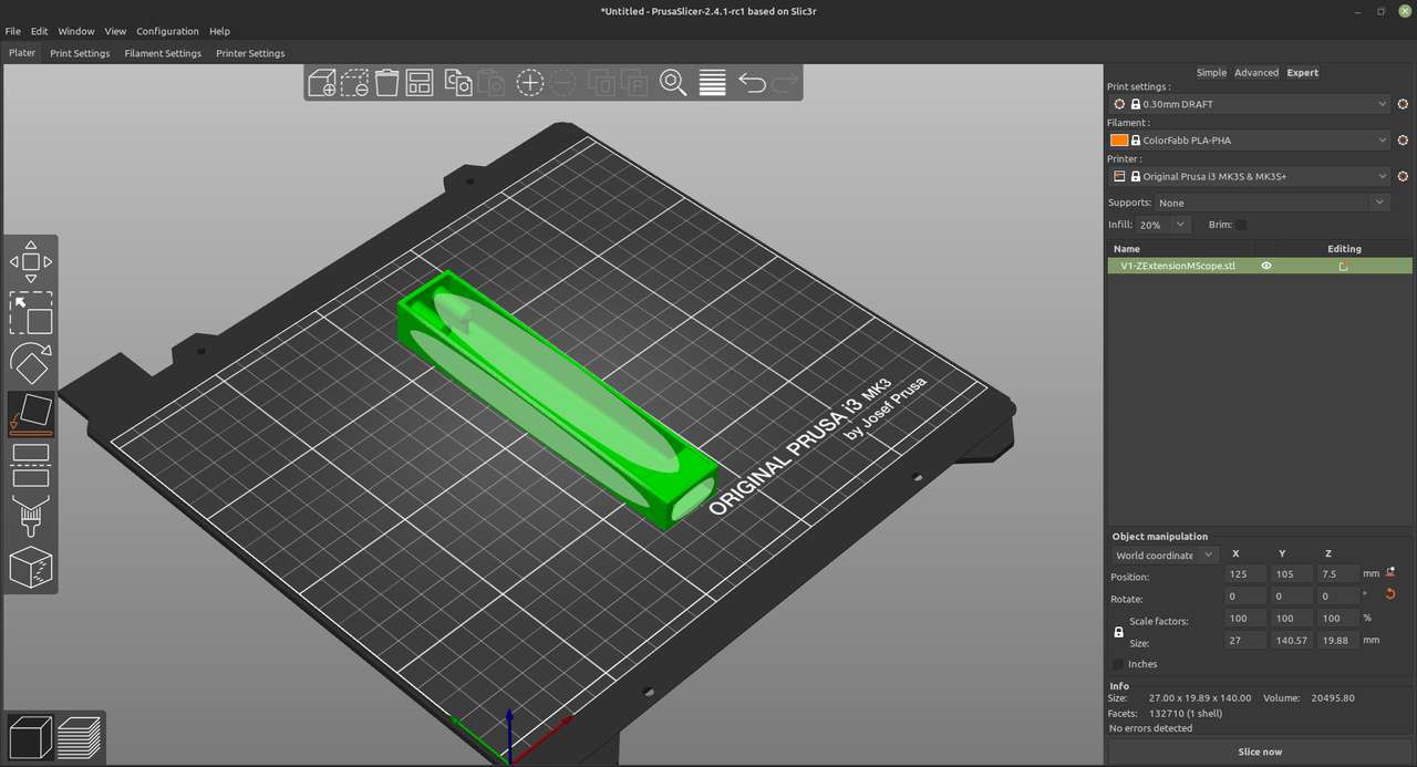
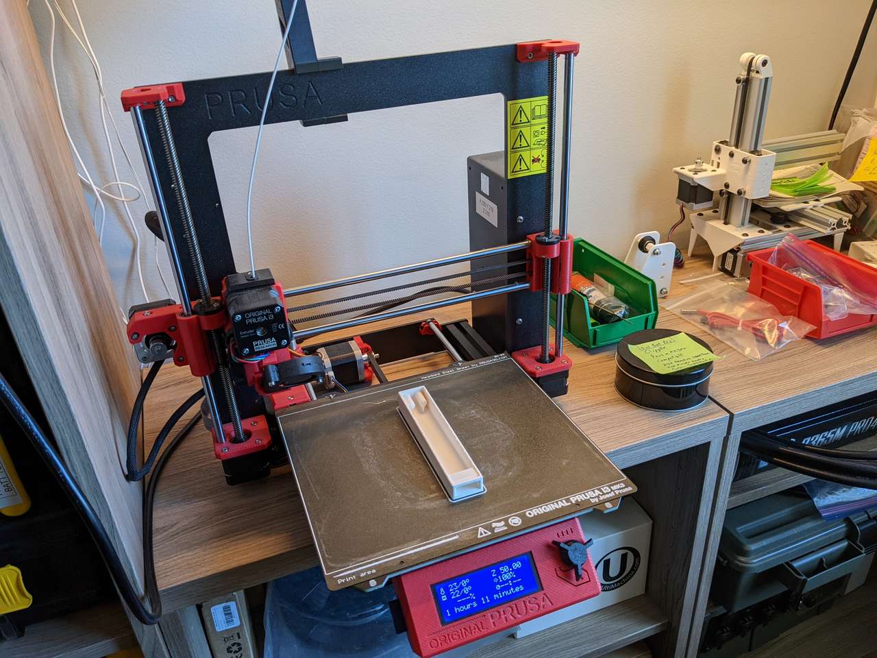
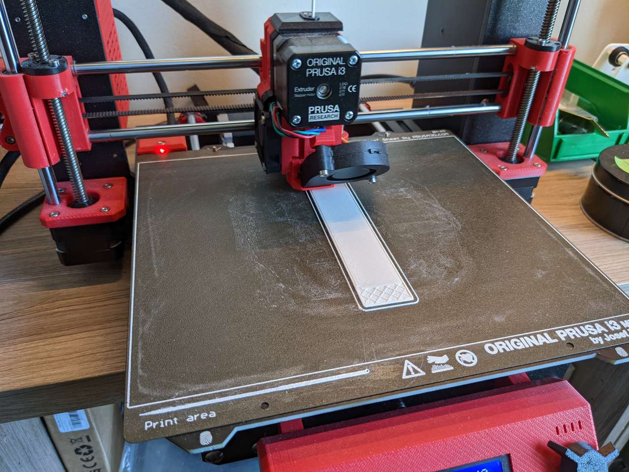
Part is placed on build plate in this orientation
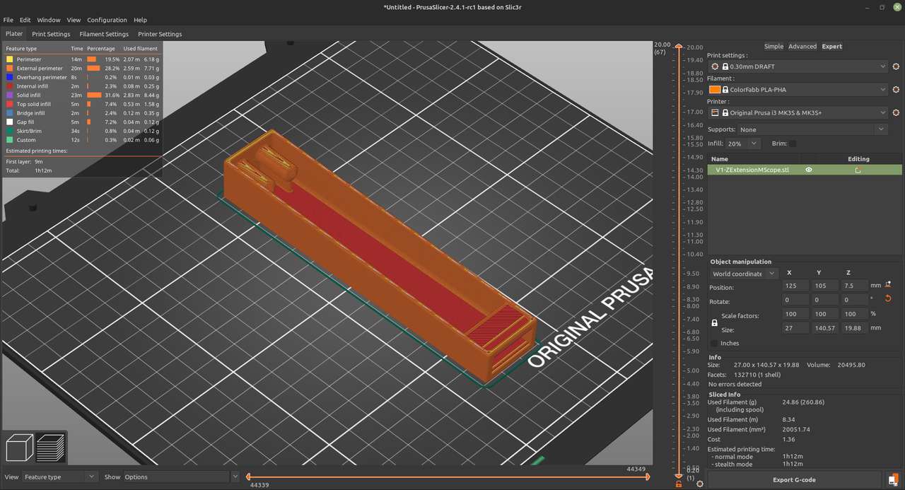
Printed with 0.30 mm layers, Colorfabb PLA-PHA, 20% Infill, no supports, no raft. Total print time 1h 12min. 25g filament costing $1.36
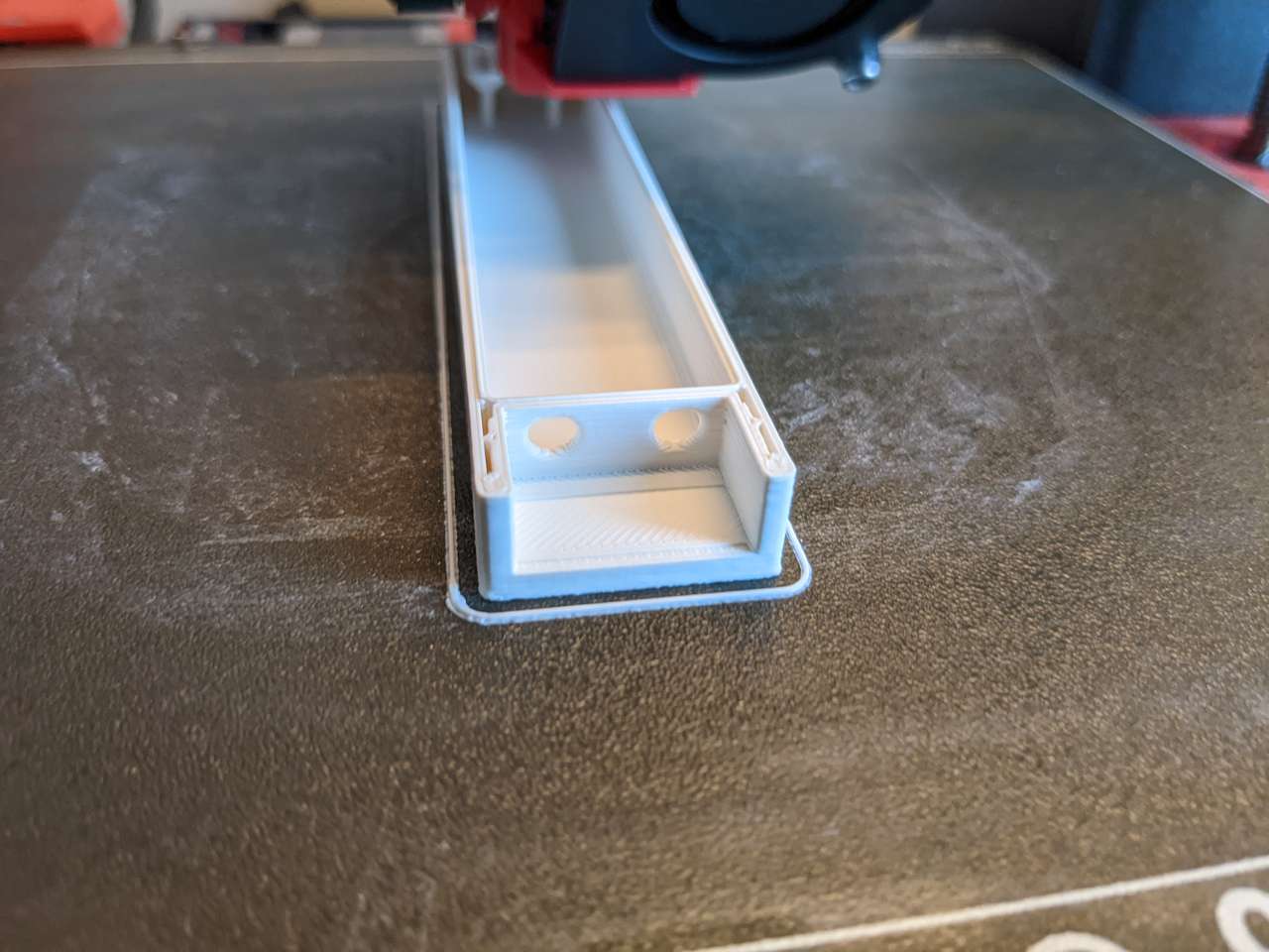
Note holes bridging without support
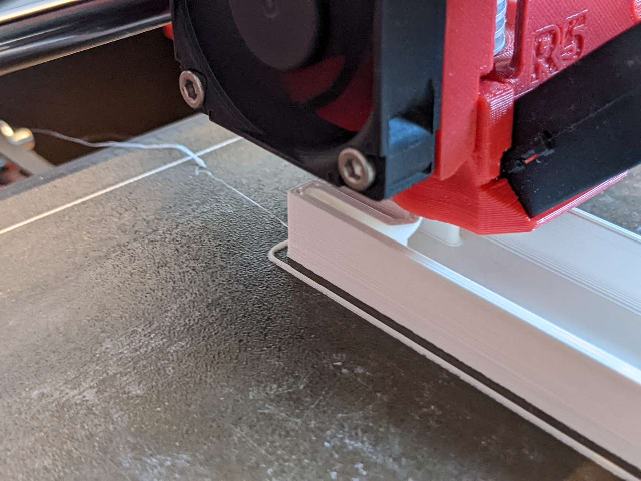
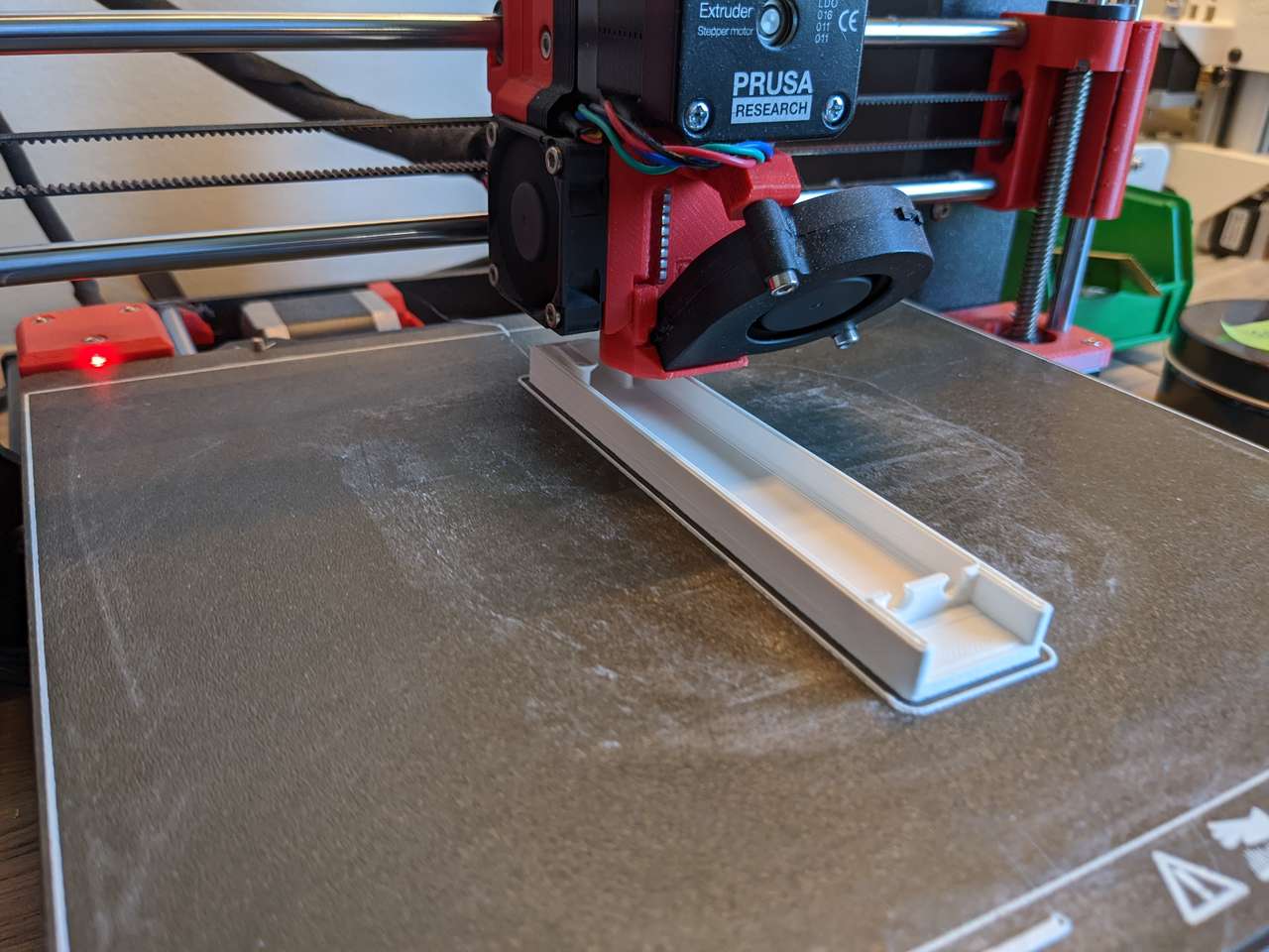
Ribs on bosses allow printing without supports and also strengthen part
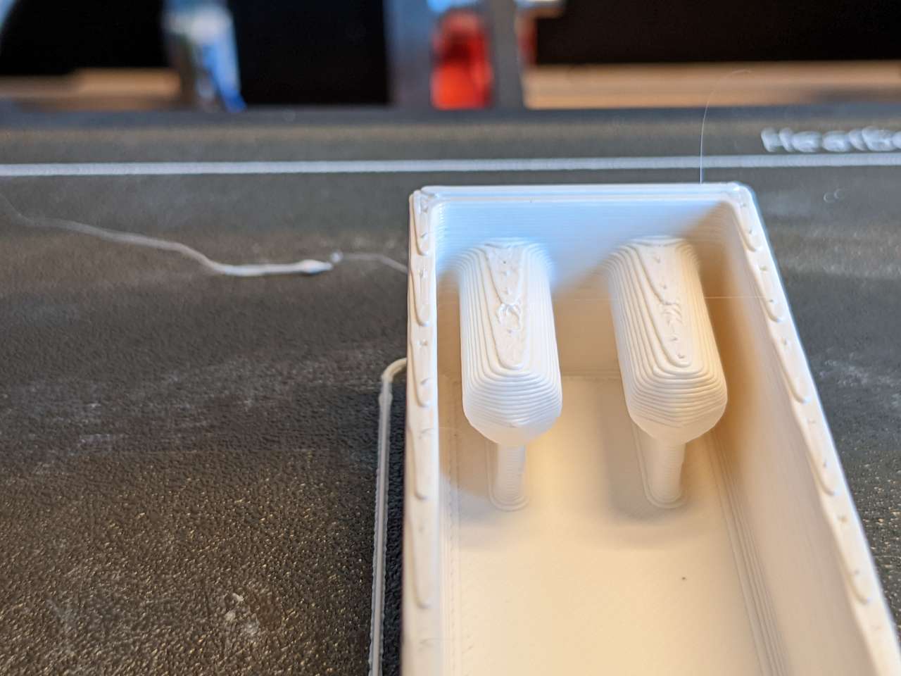
Screw bosses use designed ribs to support and strengthen
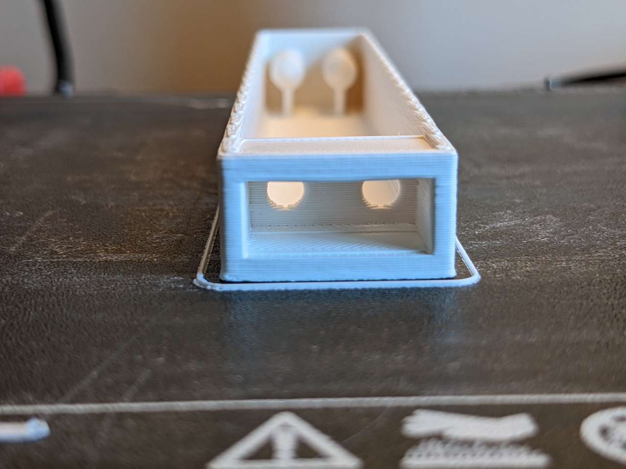
Square pocket bridged without support
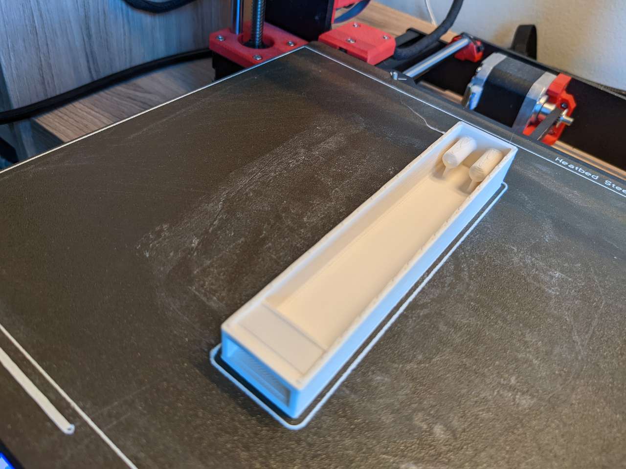
This object was printed with no supports, or raft, directly on the build plate.


Now my USB microscope’s field of view is big enough for larger parts.
3D scan an object
I decided to use the 3D Printing 101 column in our Museum of Science and Industry Chicago’s Make_X Project Grid to guide me through this activity. You may visit www.MakeCS.org if you want to learn more about the Make_X Project Grid system for use in your own Fab Lab.
See the document linked below for the steps I used to scan myself:
Wanger Family Fab Lab: HOW TO 3D SCAN AND PRINT SOMEONE’S HEAD
Of note is that we always get better results from holding the Xbox 360 Kinect in our hands overhanded (like you are going to eat it two handed like a big sandwich). Do not use a tripod as shown in the photos below, it worked but I wish I had hand held the Kinect. This means that two people are required to do scanning of people.
Below is a video of the scanning process:

Gerard and Dan check the scan cam and save ply, stl and obj files.
Prep scan for 3D printing
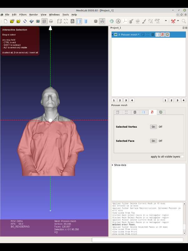
I used MeshLab software to fill holes in my scan.
I rotated and positioned my scan with the “manipulators tool”. Then I did some clearing with Filters, Cleaning and Repairing, Remove isolated pieces (wrt face num).

Then I used “surface reconstruction: screened poisson” to plug holes.
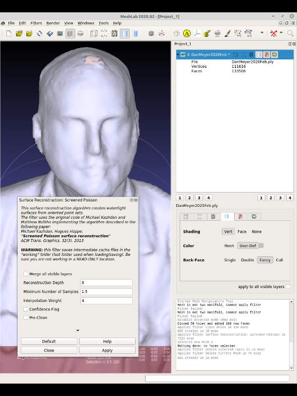
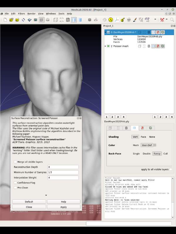 Next exported the a new ply mesh file.
Next I selected the faces of my scan that I wanted to keep by using the select faces in rectangular region icon and then inverted the selection with the keyboard key I.
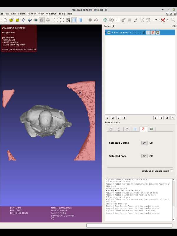
Next I pressed the delete key deleting all the extra scan surfaces.
Then I removed the bottom part of my body, since my goal was printing only my head.
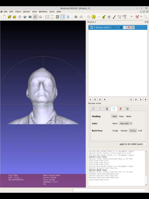
All done, now on to slicing!
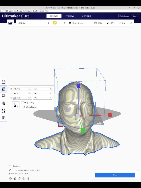
3D print the scan
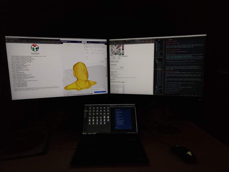
I used Cura to slice my head up.
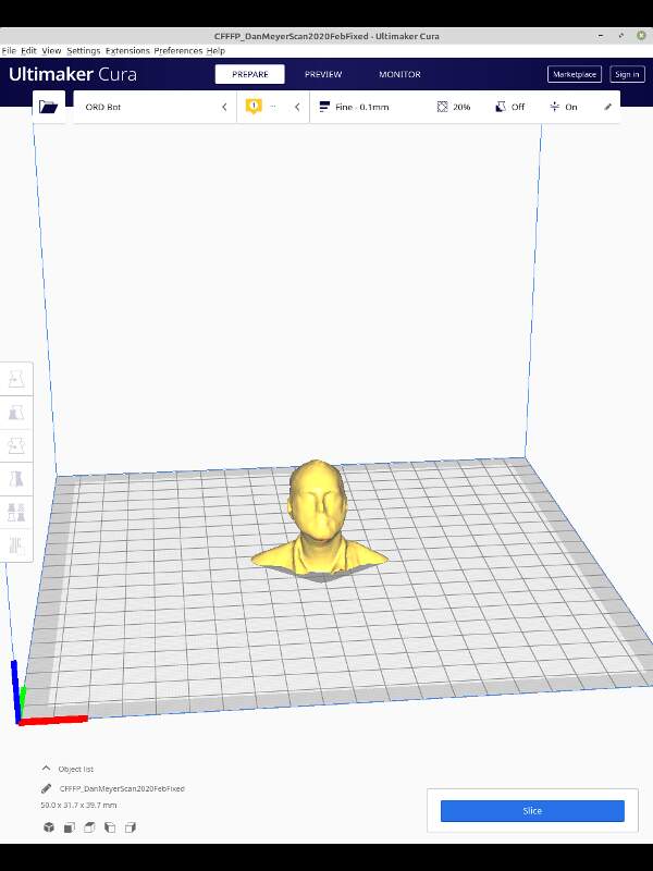
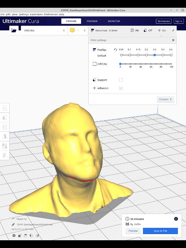
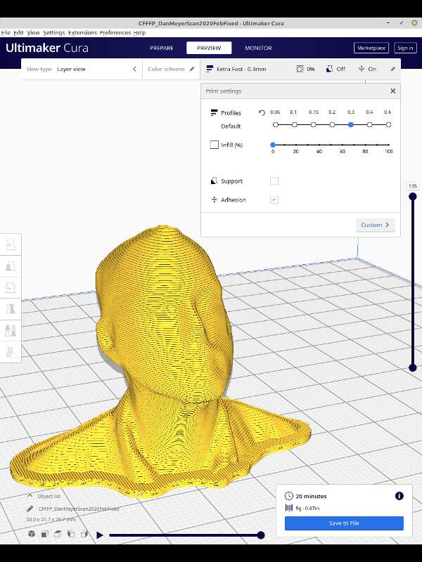
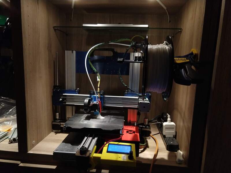
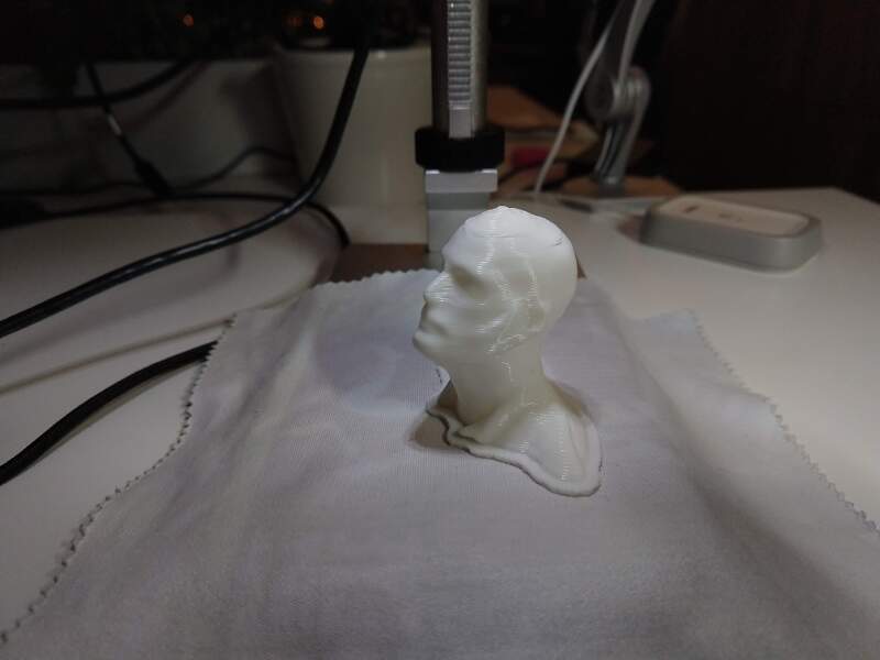
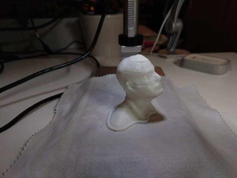
Object above was 3D printed with .3mm layer heights, 40 mm in Z height, 2 walls thick, completely hollow (no infill), with no supports, and with a 2 layer raft. This resulted in a print time of 20 minutes, which is very fast for this size object.
CAD Files
STL Files: Not required due to large size. 3D Printed Optimized Design (undercut and blind features) Z Extension for USB Microscope Stand: Native Onshape format with export and copy options
Hero Shot:
Exploring Other Worlds! (work beyond assessment requirements)
Nested objects in Dan’s scanned head using Onshape and Tinkercad. In progress, I may not finish this idea this week.