3d scanning and printing
By Alan Han, Kyle Pierre NFR, Dan Meyer
- Test the design rules for your printer(s)
- Document your work and explain what are the limits of your printer(s) (in a group or individually)
ORD Bot Hadron 3D Printer
By Dan Meyer
Dan’s ORD Bot Hadron was one of the first kitted by Designer Bart Dring. The open source ORD Bot 3D Printer was part of the i3 style kits to emerge improving upon the earlier Rep Rap Mendel, that have frames made from threaded rod. The ORD Bot uses the open source MakerSlide, also designed by Bart Dring. MakerSlide was the first open hardware aluminum extrusion slide and wheel systems to be widely tooled up and distrubuted world wide.
Design Rules STL Test File List
Design Rules for our 3D printers Print a series of test objects on the different 3D printers we have to characterize them:
| Design Rule Test | ORD Bot Hadron (Layer Height) | Ender 3 (Layer Height) |
|---|---|---|
| Nozzle Orifice | 0.4 mm | 0.4 mm |
| supported overhang | 0.3 mm | 0.35 mm |
| supported clearance | 0.3 mm | 0.35 mm |
| angle | 0.3 mm | 0.35 mm |
| overhang | 0.3 mm | 0.35 mm |
| bridging | 0.3 mm | 0.35 mm |
| wall thickness | 0.3 mm | 0.35 mm |
| dimensions | 0.3 mm | 0.35 mm |
| anisotropy | 0.3 mm | 0.35 mm |
| surface finish | 0.3 mm | 0.35 mm |
Why 0.3 mm layer heights
I 3D print almost all my parts at 0.3 mm layer thicknesses with a 0.4 mm nozzle orifice size. Most part designs do not require thinner layers, thicker layers speed up printing time. Extruder jams are less frequent as well. This also allows for a larger part to be 3D printed given the same printing time. We teach our students at the MSI Fab Lab to consider the amount of time they have to print their design and optimize for that time, this usually results in larger scaled prints at 0.3 mm layer height.
ORD Bot Hadron 3D Printer Design Rules Results
I used 1.75mm RepRapper white PLA filament running at 200deg C. Cura was used as a slicer with 0.30mm layer heights. Nozzle orifice was 0.4 mm. The nozzle system is a bowden fed open source hardware E3D Chimera with a Prusa MK3S part cooling fan and duct.


The ORD Bot does a good printing overhangs with support, the support was removed easily and cleanly.

The ORD Bot can print functional clearance gaps up to 0.3mm at 0.2mm the gap fuses shut.

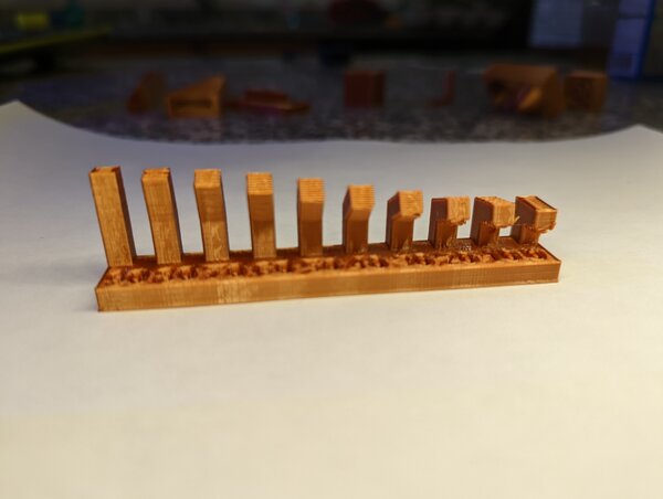
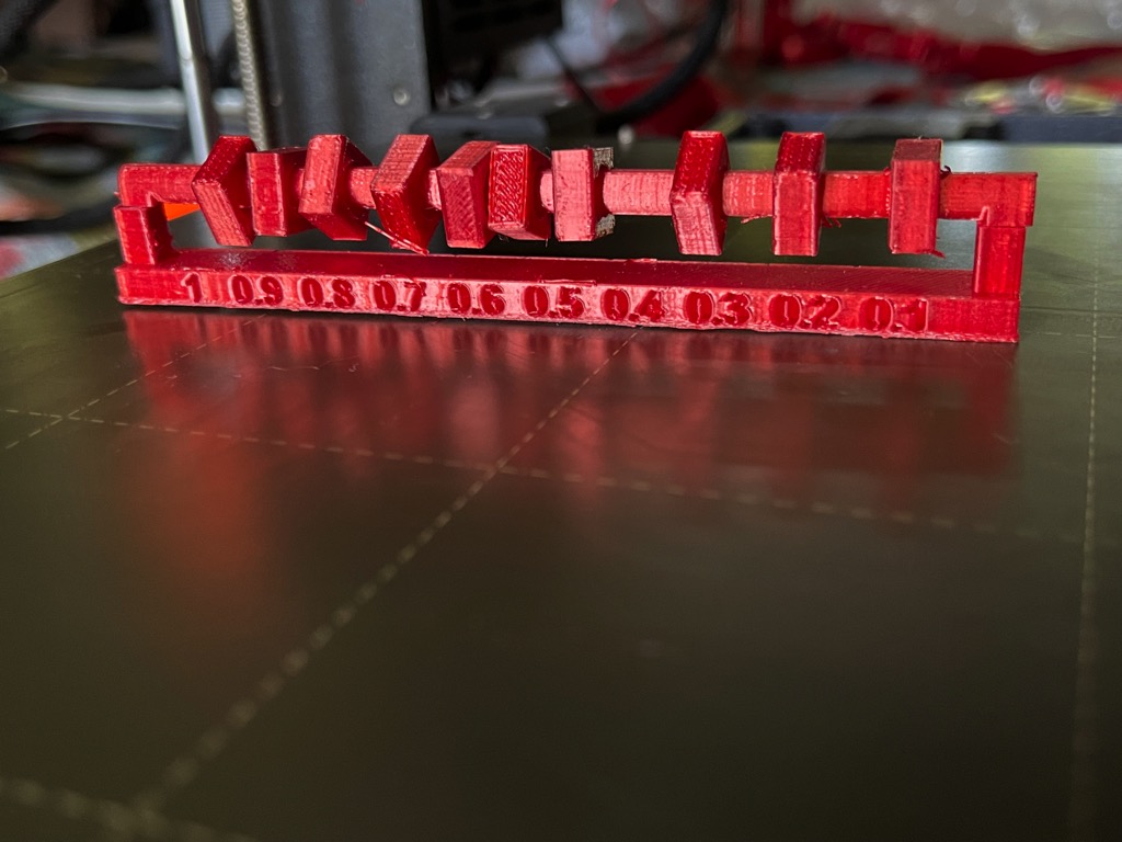
ORD Bot overhangs are clean up to an angle of 30 degrees. 20 degrees has some drooping. 10 degrees is very droopy.

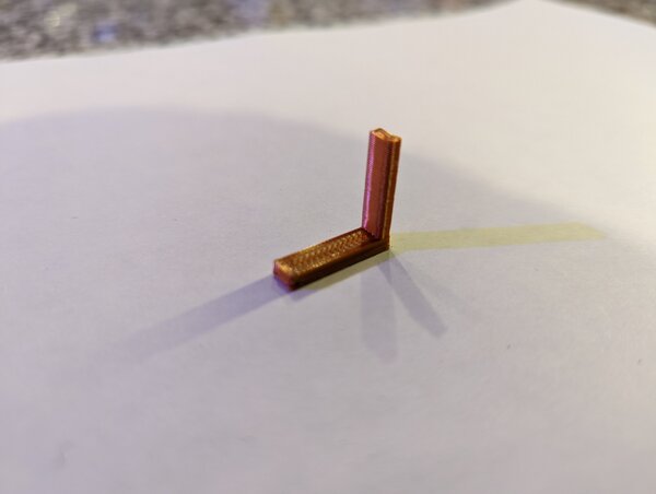
ORD Bot can do 90 degree overhangs of 1mm wide, at 2mm wide drooping starts immediately. At 3mm drooping is quite severe. at 4mm a significant amount of the feature is lost to drooping.
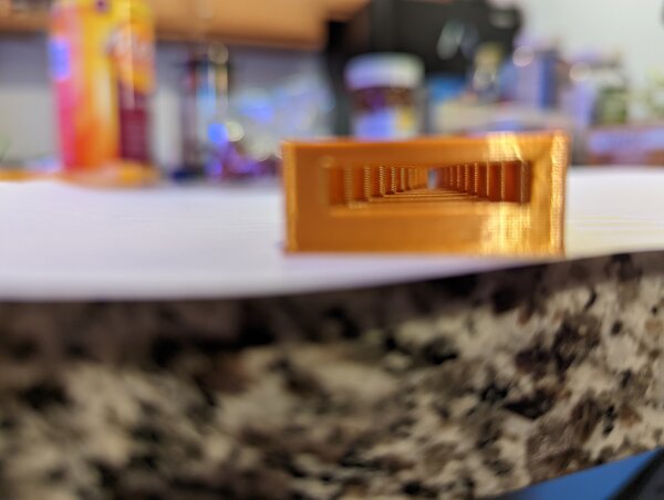
The ORD Bot is very good at bridging, the video above shows the bridging results.

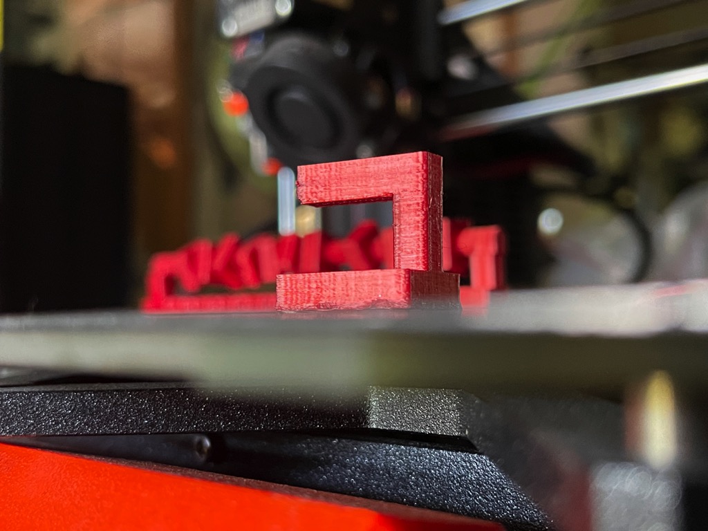
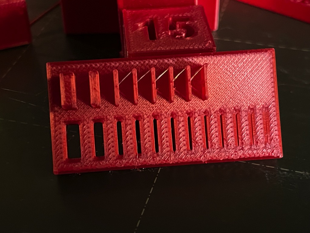
The ORD Bot can print at .3mm layer heights: .5mm thick walls and .3mm thick slots.
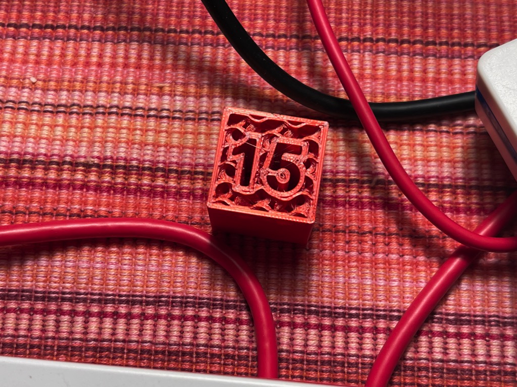
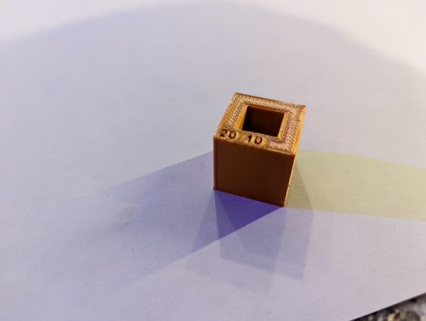
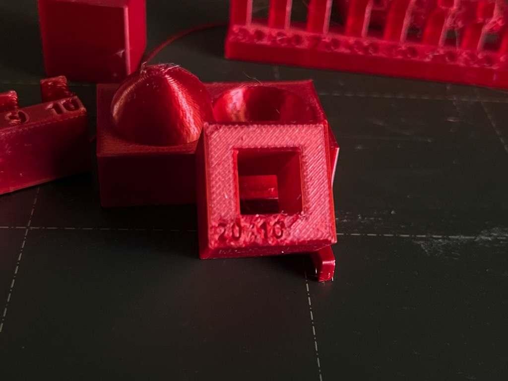
For the dimension test the inner square opening measures 9.6 to 9.75mm with a digital calipers. The outer square dimension measures 20.25 to 20.3mm. These undersized and oversize characteristics can be informative during the design process.

I don’t see many artifacts in the anisotropy test.


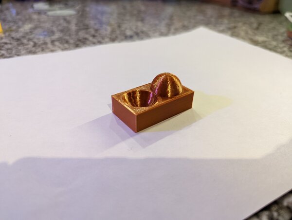
The surface finish test looks pretty good considering the 0.30mm layer heights.
Conclusion: Design Rules results
The ORD Bot shocked me with the quality it could produce. My ORD Bot is somewhat of a Frankenstein DIY 3D printer, using whatever parts I could afford and was interested in at any given time added to it. My ORD Bot is quite old with its first successful prints in 2012 after several failed attempts in 2011 shortly after being built.
I now understand the limitations of my ORD Bot running PLA with 0.3 layer heights. Most test prints limitations seemed to be related to the 0.3mm layer height and not the ORD Bot mechanics. Most important to me is the dimension test verifies that at 0.3 mm layer heights: 1. A 0.3mm max oversize condition is present on outside dimensions. 2. A 0.4 max oversize condition is present on inside dimensions.
These clearances verify why I find a 0.3 to 0.6mm clearance to work well on parts that slip together with minimal to no effort.
Here is a summary chart of the results with the max value that is acceptable for my 3D printing expectations:
| Design Rule Test | Max Value or Pass/Fail |
|---|---|
| supported overhang | Pass |
| supported clearance | 0.3 mm |
| angle | 30 deg |
| overhang | 1mm |
| bridging | 20 mm |
| wall thickness | 0.5mm walls, 0.3 mm slots |
| dimensions | 0.3 mm outside swell; 0.4 inside swell |
| anisotropy | minimal artifacts |
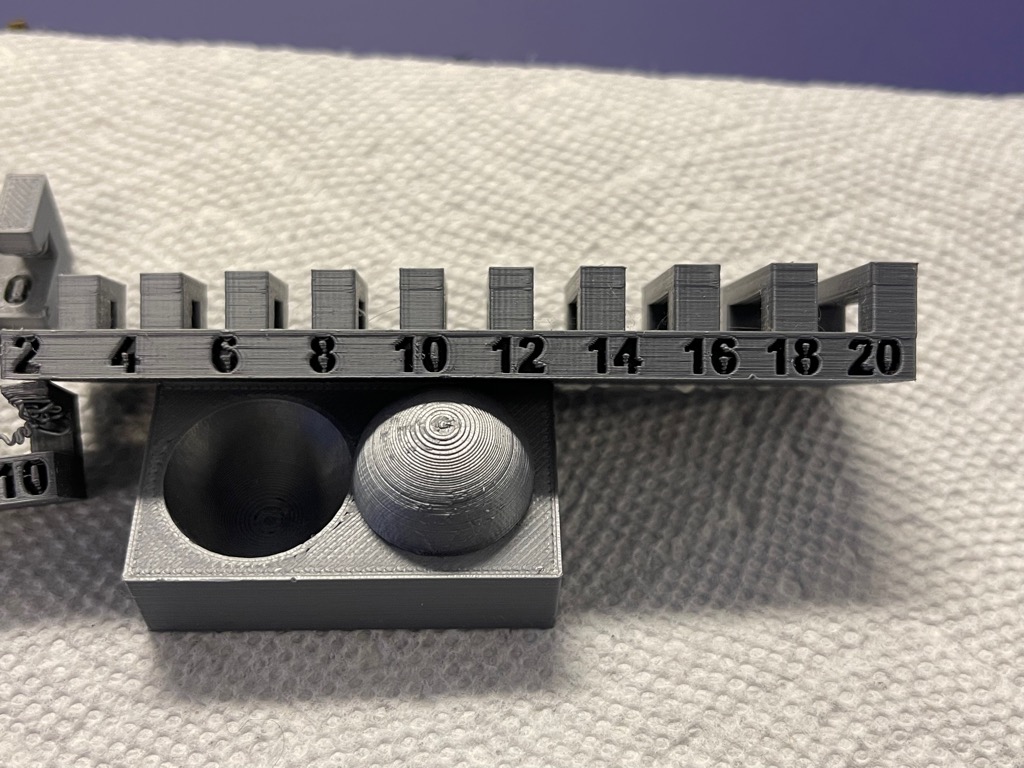
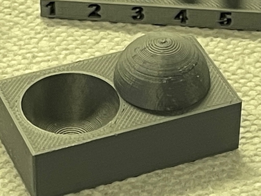
| surface finish | 4th layer of sphere apex |
Ender 3
By Alan Han
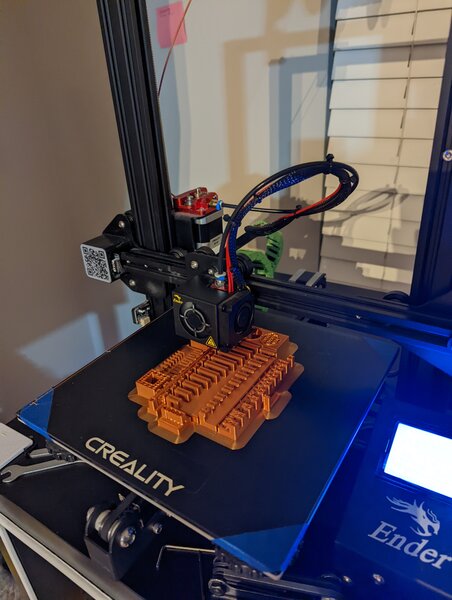
The Ender 3 is a ubiquitous FDM 3d printer in the 3d printing community, commonly found for $200 or less. Given its cost, the quality can be surprisingly good. At the time of printing, this machine had minimal modifications: - XS Capricorn tubing - stock brass nozzle
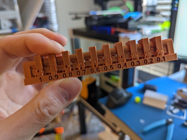
overhang (printed w/ supports)
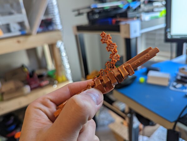
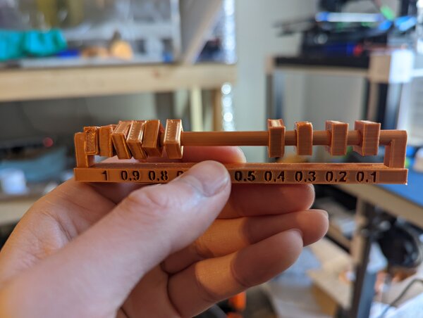
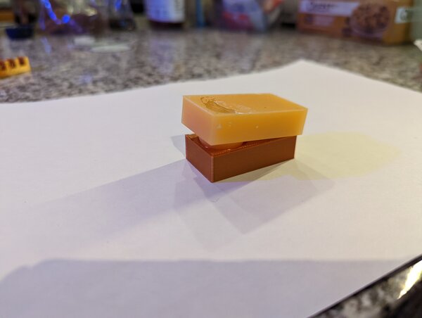
clearance (printed w/ supports)
I printed this part with supports as indicated.
Supports were removed w/o destroying the part. Some of the supports were difficult to remove (between the top of the rod and the rings (0.3, 0.2, and 0.1). 0.4 was loose, but tight enough that rotation was free with resistance.
1.0 to 0.4: loose 0.3 to 0.1: not loose
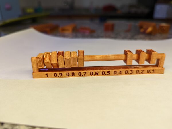
angle
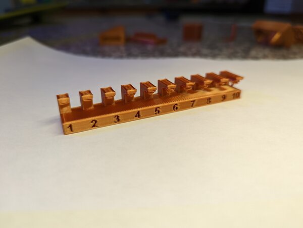
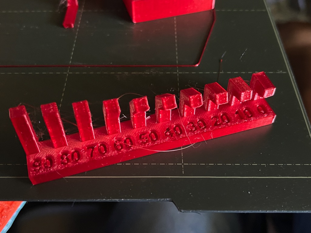
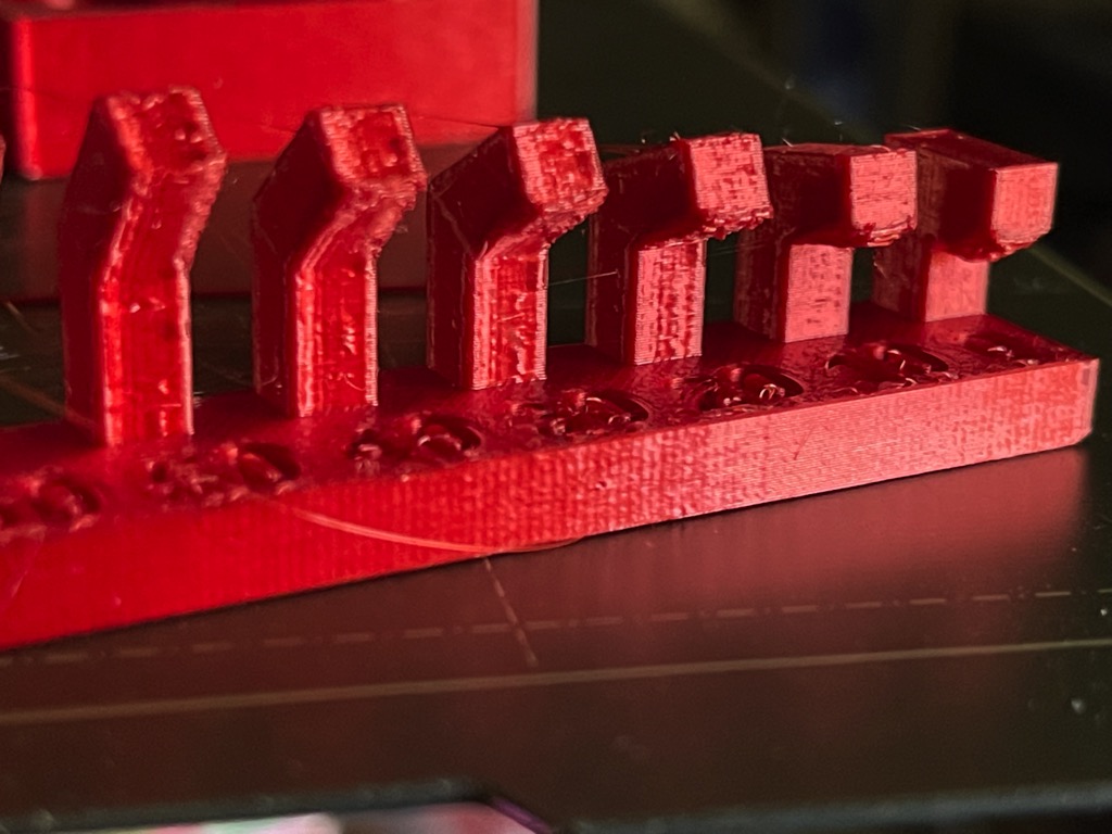
I start to see some droop starting around 40 degrees. 30, 20, 10, 0 all progressively get worse.
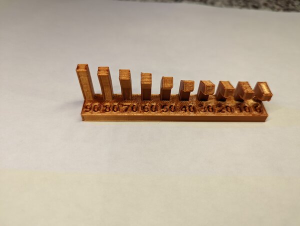
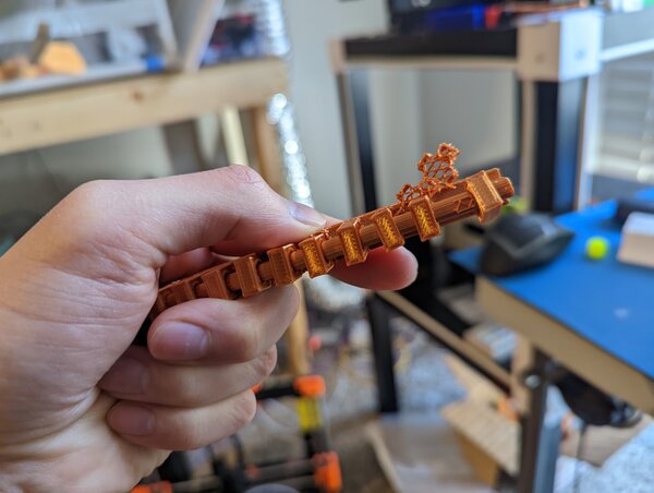
overhang
I start to see droop at 2. 3, 4, 5… onwards progressively get worse. The top 3-4 layers are typically intact, despite worse initial layers.
bridging
The bridging tests all seemed to do well.

wall thickness
slicer appeared to stop rendering starting with 0.4mm thick. this makes sense; the nozzle being a 0.4mm-wide orifice.
anisotropy
prints in the z-direction have a much cleaner finish than same geometry in xy-direction. If I apply ironing, I’m sure I could get a better finish.
surface finish
I can’t tell if it’s the filament, but the surface finish is nice (for FDM). Note that my layer height was 0.35mm.
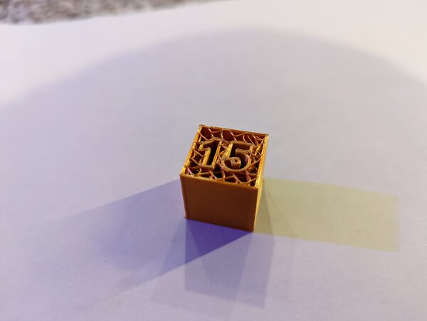
infill
I used gyroid for infill. I see that the layer adhesion is a bit poor between some of the layers.
Prusa i3 Mk3S/+
By Kyle-Pierre Nfr
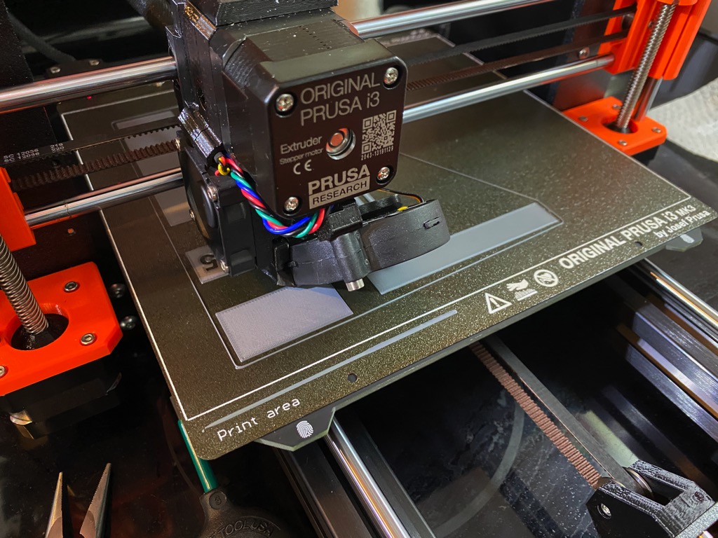
This section reports on the characterization of the Prusa i3 MKS and S+ printer.
Background
We became familiar with the RepRap model at a printer build for SeeMeCNC printers in 2012 or so. Joesef Prusa and Zach Kaplan of Inventables were both their. While we were at the event to see the delta printers, people kept referring to Josef as a “RepRap” developer. We were unfamiliar with them, but the RepRaps that we saw at the time were fairly under developed relative to the SeeMeCNC machines. In addition, the SeeMeCNC is based in Goshen, Indiana. So, we ended up buying two of their kits. Fast-forward to 2017, we met some kids who made and were selling mechatronics development kits that included parts printed by Prusa i3s. The parts looked pretty good. We were also looking to upgrade our delta printers. So, we boutght a couple i3MK3S printers. They offer several advantages over other printers. Among them are bed-leveling, filament sensor, removable print sheet. But, the control software is what we appreciate the most. It provides for power-loss print recovery for example. Combined with the Prusa slicer, we have been able to produce very satisfying results. As a side note, I should say that the distributed, digital-fabrication work that Adrian Bowyer fostered ultimately led us to Fab Lab and Fab Academy.
Objective
Below, I will describe the prints of the models supplied to students to characterize our 3D FDM printers. I will identify the design limitations that these prints exposed.
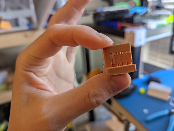
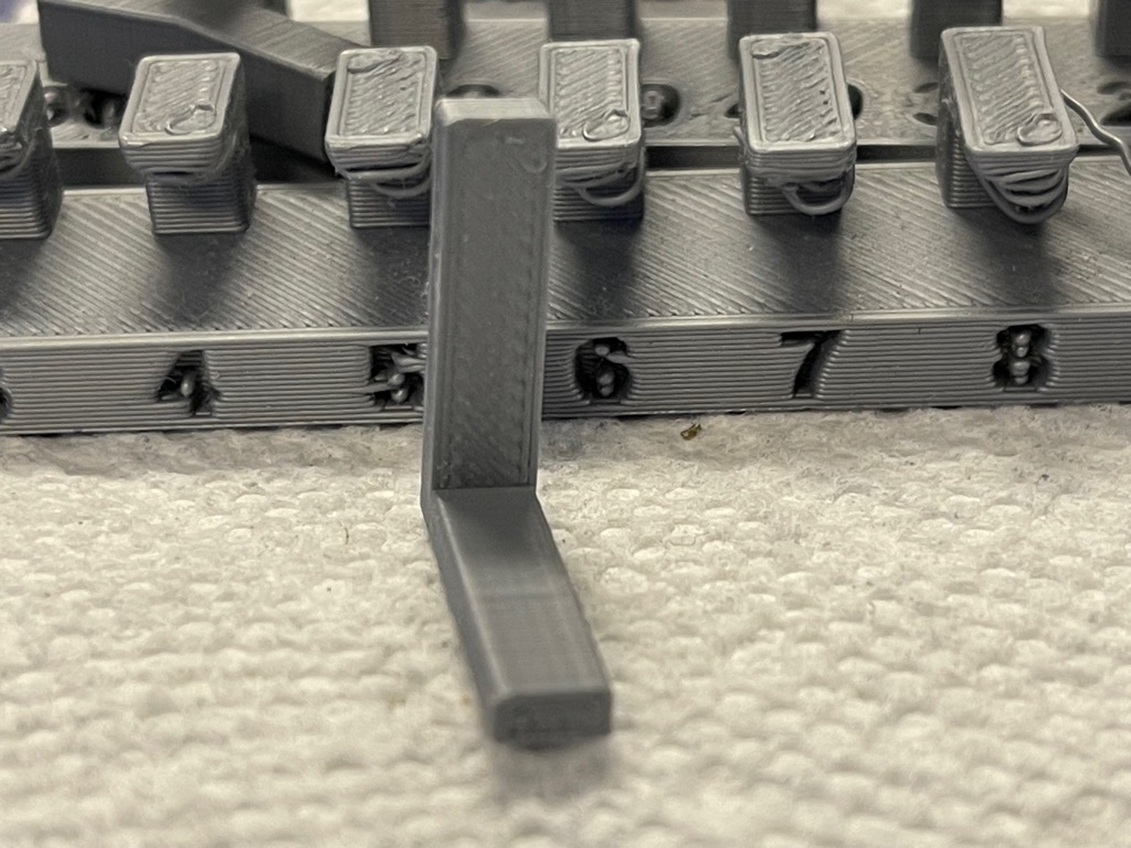
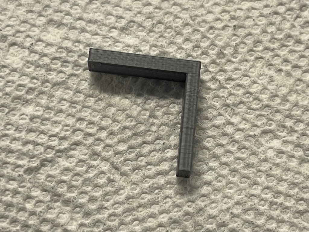
Overhang (printed w/ supports)
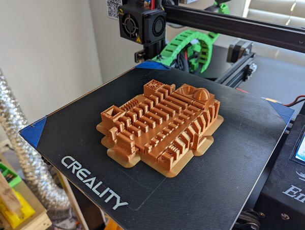
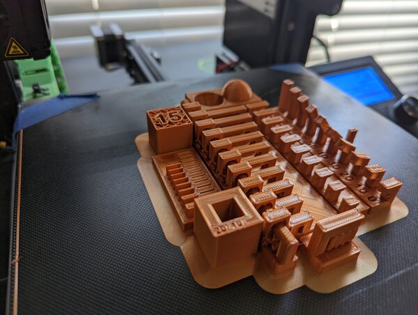
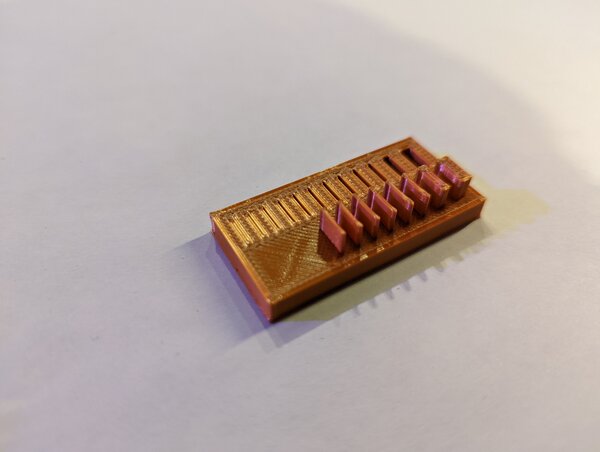
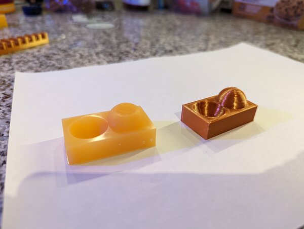
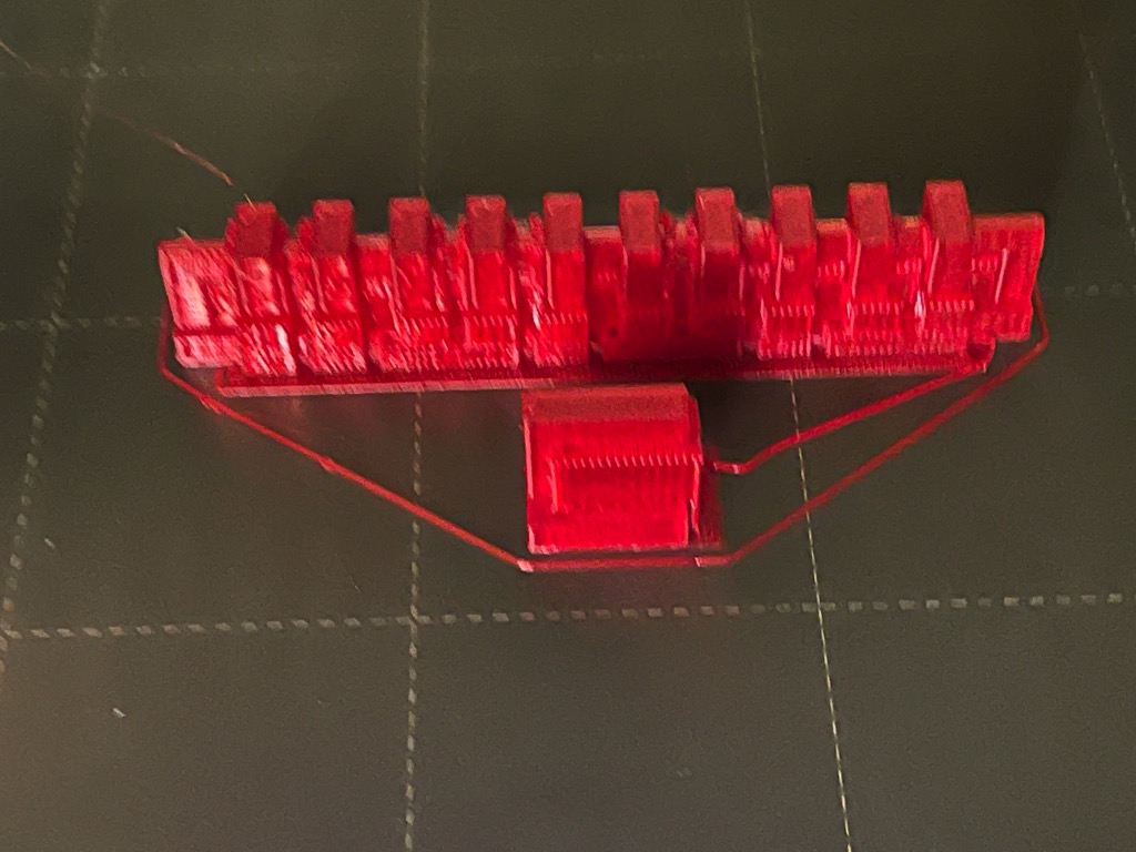 This image shows both “overhang” and “clearance” prints with supports still attached.
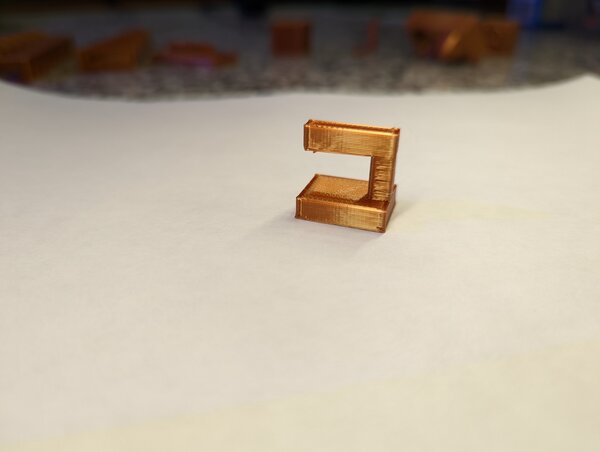
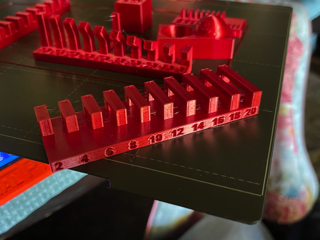
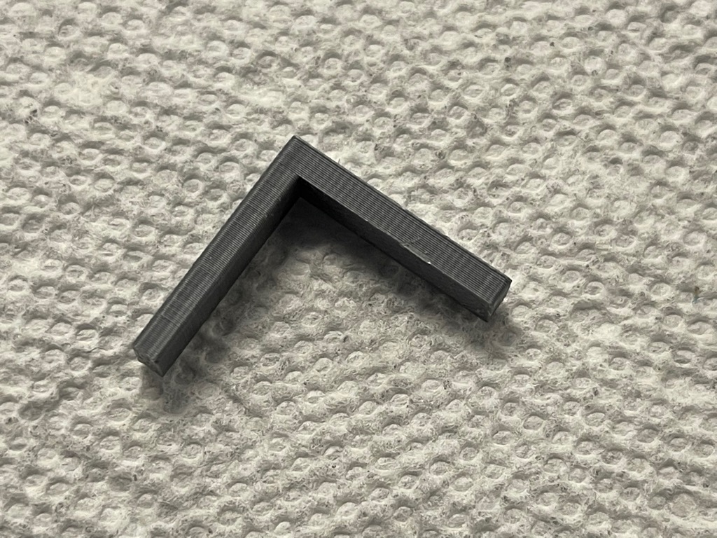
 Red prints were made with this 1.75mm PLA filament. Grey prints were made with this 1.75mm PLA filament. This image displays the overhang print with the supports removed. The angle of the overhang is 90 degrees.
The supported overhang produced acceptable prints. I detected no “delamination” on the bottom of the overhang.
Red prints were made with this 1.75mm PLA filament. Grey prints were made with this 1.75mm PLA filament. This image displays the overhang print with the supports removed. The angle of the overhang is 90 degrees.
The supported overhang produced acceptable prints. I detected no “delamination” on the bottom of the overhang.
Clearance (printed w/ supports)
Angle
Bridging
Wall Thickness
Anisotropy
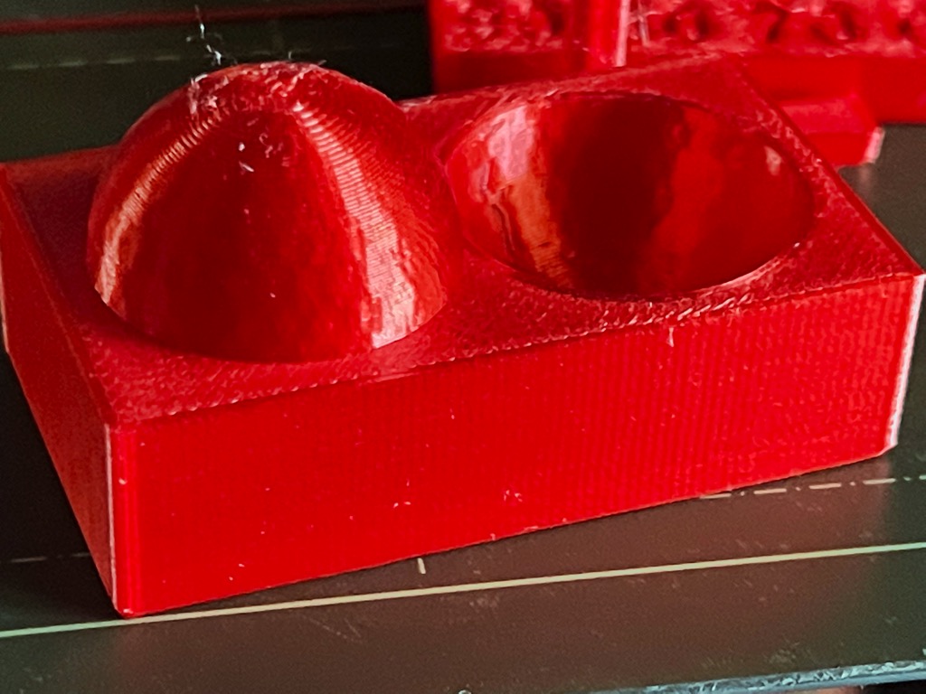
Surface Finish
Infill