Input Devices
Group Assignment
- Probe an input device(s)’s analog and digital signals
- Document your work to the group work page and reflect on your individual page what you learned
i2s mic
Alan worked on interfacing with an i2s mic.
After getting my logic analyzer setup, I try sampling the signals at 1Mhz. The resulting packets appear to have inconsistencies (in blue, “received…”)
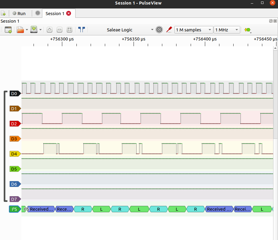
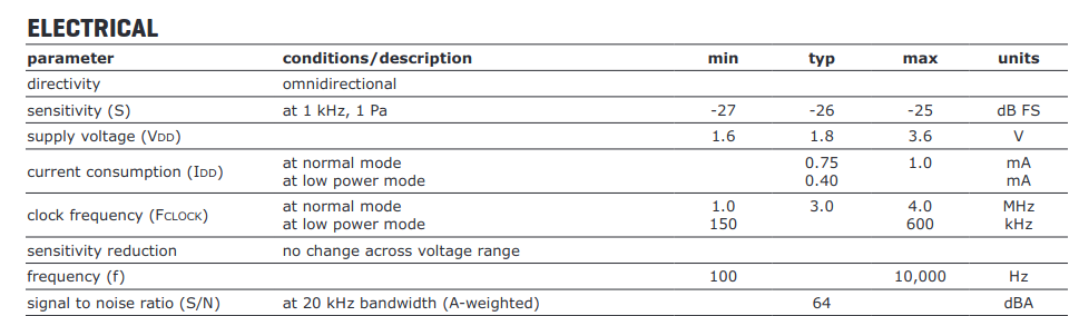
Reading the datasheet, I see that the clock frequency is at max 4Mhz.
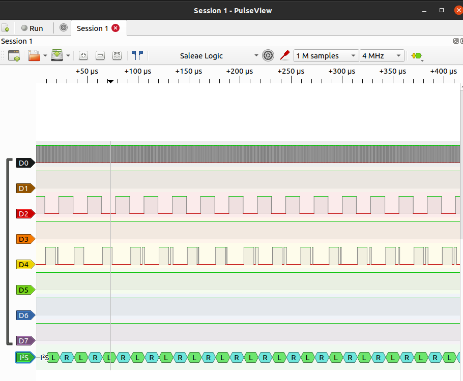
Setting the sampling frequency to 4Mhz seems to do away with the inconsistencies.
hall effect sensor
Dan worked on interfacing with a potentiometer and hall effect sensor mounted to RC control sticks.
potentiometer gimbal
Analog Levels
 Above: Typical wire color meaning, but always check your wires to be sure.Source
Dan measured the resistance of his potentiometer gimbal and recorded the following measurments
Above: Typical wire color meaning, but always check your wires to be sure.Source
Dan measured the resistance of his potentiometer gimbal and recorded the following measurments
- Between the red and black wires a total fixed resistance of 4.85 kΩ, this seems to be 5k potentiometer
- Between the red and yellow wires with the gimbal pushed left 4.3 kΩ
- Between the red and yellow wires with the gimbal pushed right 410 Ω
- Between the black and yellow wires with the gimbal pushed left 900 Ω
- Between the black and yellow wires with the gimbal pushed right 4.8 kΩ
Digital Levels
Using MircoPython the above analog signals were converted to a digital output using the analog to digital conversion feature of the ESP32 on GPIO 04 and boosting the signal by 11db.
Above: Video of Thonny IDE MicroPython code for potentiometer gimbal input showing changing values with 11db of signal Attenuation via Thonny Shell. Values between 530 and 4095 were recorded.
code
MicroPython Code “esp32ReadAnalog.py” with comments explaining my understanding of the code.
# Complete project details at https://RandomNerdTutorials.com
# modified by Dan "MTek" Meyer 2022-Jul-31 Sun 9:44pm

from machine import Pin, ADC   #ADC=analog digital conversion
from time import sleep

pot = ADC(Pin(04))             #pick your boards GPIO pin
pot.atten(ADC.ATTN_11DB)       #Full range: 3.3v with x db signal attenuation

while True:                    #while loop forever?
  pot_value = pot.read()       #read the pot value
  print(pot_value)             #print pot value to shell
  sleep(0.1)                   #pause x.x seconds between reads