Mechanical Design
Assignment
Mechanical Design (part 1 of 2)
Group Assignment
- Design a machine that includes mechanism + actuation + automation
- Build the mechanical parts and operate it manually.
- Document the group project
Machine Design (part 2 of 2)
Group Assignment
- Actuate and automate your machine.
- Document the group project
Core Crawler (AKA Foam Crawler)
CoreCrawler CNC
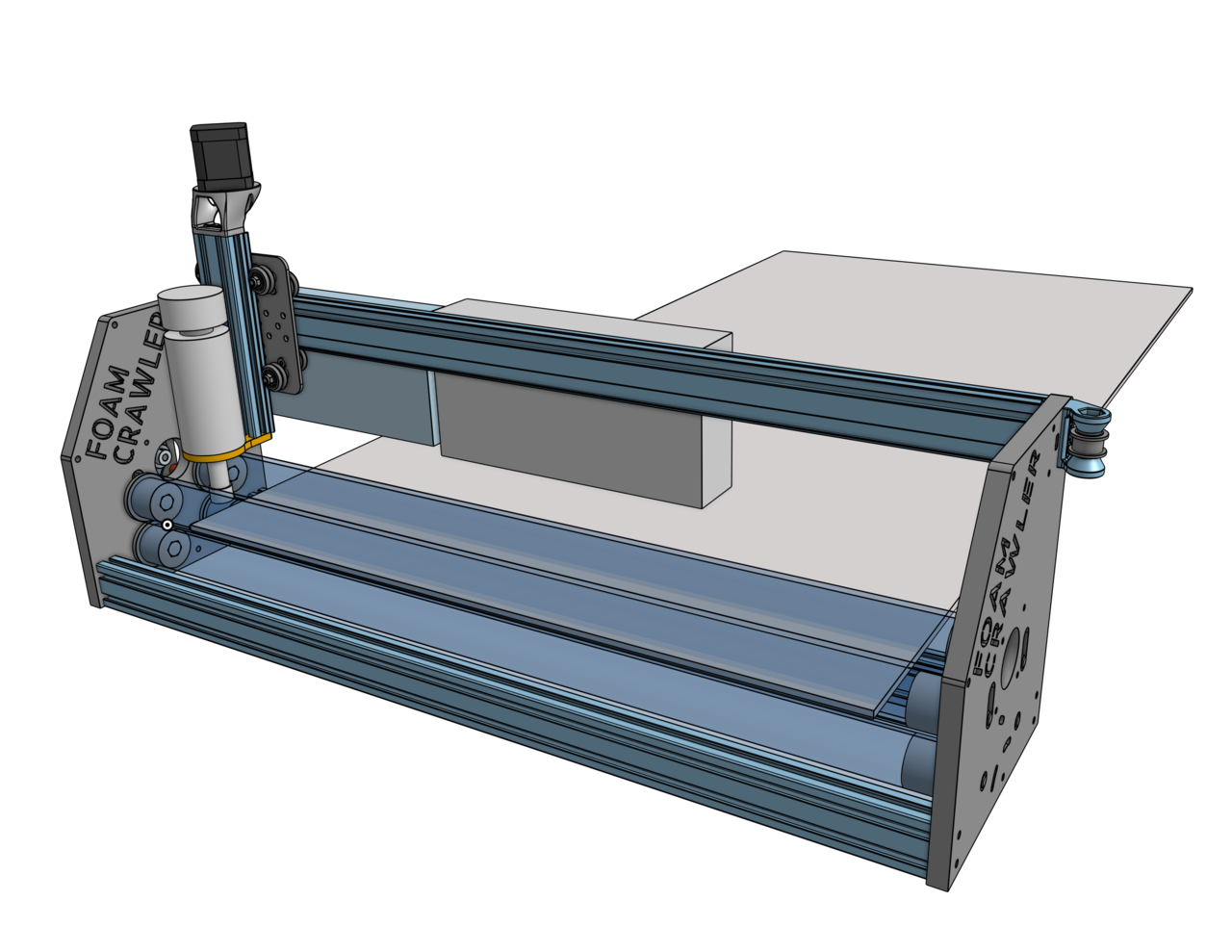
The Core Crawler machine is a 4DOF machine that typically accepts foam sheets as inputs and returns cut foam parts as outputs. Dan designed the core machine for his final project from a previous fabacademy cycle.
Task delegation
Dan: Core System Design, Core Crawler
Dan designed the core system, called the Core Crawler, and recently added fasteners and other components to complete the BOM
Dan’s Mechanical and Machine Design Documenation
Alan: Urumbu Crawler Variant
Alan is modifying the machine to run the Urumbu architecture, using pen plotting as a demo
Alan’s Mechanical and Machine Design Documenation
Kyle-Pierre: Bend Crawler Variant
Kyle-Pierre is designing a variant that would bend acrylic sheets
Kyle-Pierre’s Mechanical and Machine Design Documenation
Kyle-Pierre and Dan In-Person
On May 1, 2020 Kyle-Pierre visted Dan locally in Chicago on his way home to Indiana. Dan and Kyle-Pierre discussed the Bend Crawler and the Fab Lab Shop concepts.
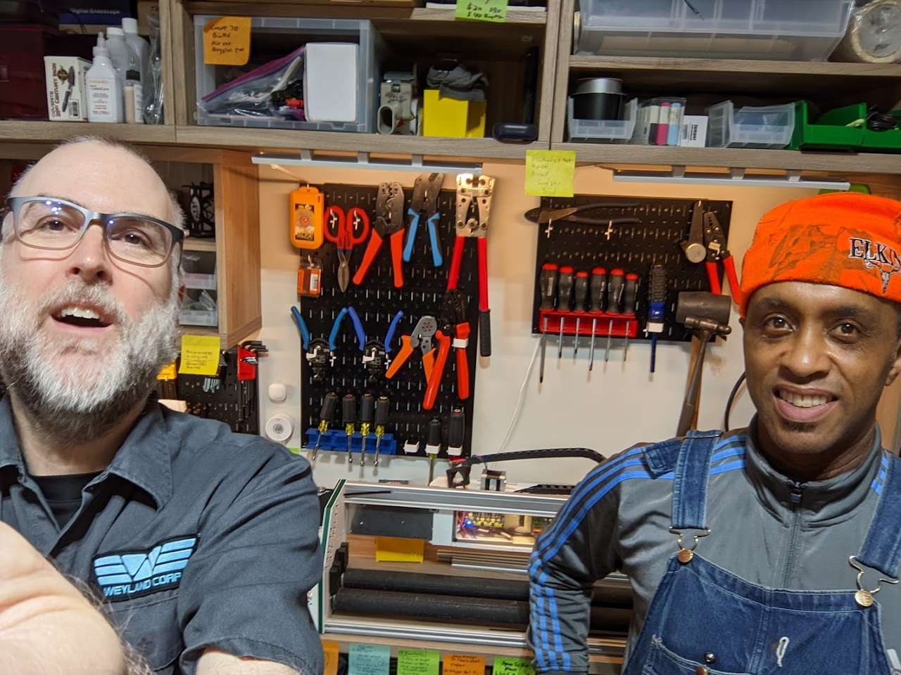 Here is a photo of Kyle-Pierre and Dan in front of th orginal Core Crawler machine.
Core Design: Core Crawler
The Core Crawler machine is designed in Onshape. It has two X Axis rollers covered in grip tape It has two Y Axis drive rollers no platen at all. It has two un-driven upper rollers. The Z axis is 8mm Metric Acme Lead Screw, X Axis is belt drive on makerslide. These 3 different drive types will be interesting to actuate manually by hand.
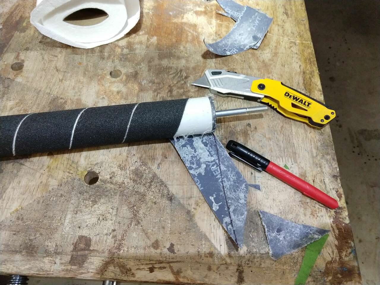
There have been a few iterations of the Y roller drive. The first was PVC pipe spiral wrapped with emery cloth glued onto PVC pipe.
Manual Operation
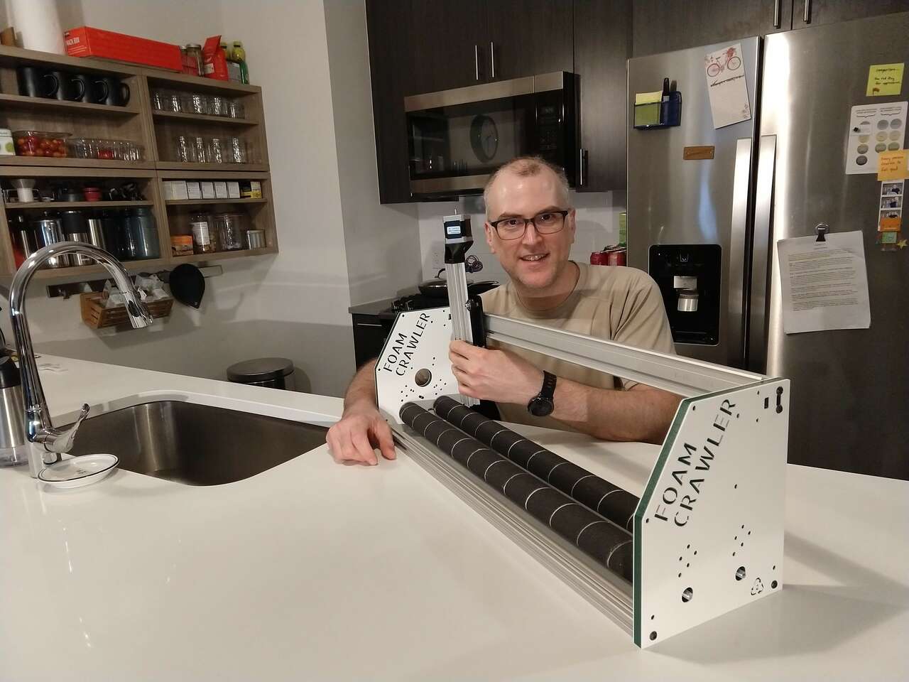 Here Dan holds the parts in place to run each axis by hand.
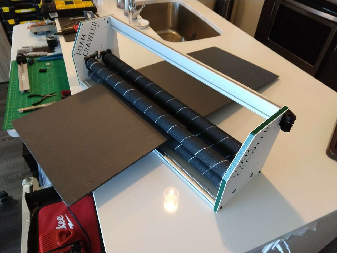 When run by hand with a piece of foam this setup has a few issues.
1. The foam would work it’s way along the x axis due to the spiral and the PVC pipes were hard to buy without bending and roundness defects, leading to a kind of clapping onto and off of the foam sheet while being driven.
2. The hand operation also revealed that accelerating and decelerating the rollers took a surprising amount of force.
3. The M8 bolts were also loose in the bearings leading to slop.
When run by hand with a piece of foam this setup has a few issues.
1. The foam would work it’s way along the x axis due to the spiral and the PVC pipes were hard to buy without bending and roundness defects, leading to a kind of clapping onto and off of the foam sheet while being driven.
2. The hand operation also revealed that accelerating and decelerating the rollers took a surprising amount of force.
3. The M8 bolts were also loose in the bearings leading to slop.
Kyle-Pierre Nfr Version
Kyle-Pierre Nfr would like to modify the core crawler to index acrylic sheets over a heating element. Once the acrylic is soft paddles would bend the acrylic to a specific angle and let the acrylic cool. Then the acrylic would advance and the process would repeat. One use for this process would be for machine covers. Even with this modification the Core Crawler could be used as originally designed.
Here is an industrial machine similar in function to what Kyle-Pierre is Designing
Actuate and automate your machine
GRBL gSheild Setup
We have a lot of Synthetos gShield CNC controllers in stock, so that’s what we used to actuate the Core Crawler. The instructions for connecting the gShield we used are here: Using grblShield
We compiled, flashed, programmed and setup the gShield cnc control using grbl.
Installing and getting USB to work with the Arduino IDE on Linux is not well documented. Here is a good post to help: Arduino IDE on Linux Mint
The GRBL wiki has good instructions on how to compile and install GRBL: Grbl wiki!
Universal Gcode Sender(UGS)
To send gcode we decided to use Universal Gcode Sender(UGS) software in the “platform” flavor. The download for linux platform UGS was located at: https://github.com/winder/Universal-G-Code-Sender.
After wiring up my 24VDC power supply, we plugged a USB cable between my computer and the Arduino UNO with gShield.
We fired up UGS and clicked the Port: to select the port the Arduino UNO was on.
Then we clicked the “Machine” and then “Connect”… and GRBL initialized and talked back! YES!
It’s Alive!
We then executed some jog moves, they worked moving my X and Y axis along with lighting up the green lights on the gSheild stepper outputs! Although the movements were very weak. We needed to set stepper driver currents.
Setting Stepper Currents
We used the procedure on the synthetos/grblShield wiki Setting Motor Current to intially set the stepper motor currents.
Later we will verify the current settings with Vref measurements. This is a good guide on that process: Setting the stepper motor current limit from this page “The gShield (version 5) uses a 0.1 ohm current sense resistor so the formula is Vref = 0.8 * I.
The maximum current the driver chip can deliver with appropriate cooling is 2.5 amps. To use this current value you would set the Vref voltage at (0.8 * 2.5 amps) = 2 volts. This is the theoretical current limit.”
Note: the gSheild stepper driver are limited to 2.5 amps
| Stepper | Multiplier | Target Amps | Vref |
|---|---|---|---|
| NEMA 28 X&Y Axes KL23H251-28-4A | 0.8 | 2.5 A | 2.0 V |
| NEMA 17 Z Axis SM42HT47-1684B | 0.8 | 1.68 A | 1.3 V |
Steps per mm
Next we used the GRBL settings calculator to get the correct distance movements. We also found the Norwegian Creations Tutorial: Calibrating Stepper Motor Machines with Belts and Pulleys useful for the roller drive calculations. Grbl v1.1 commands can be found here: (https://github.com/gnea/grbl/wiki/Grbl-v1.1-Commands) We also found the FABLAB León LE-CAR-BIL MACHINE documentation useful.
Our steps per mm calculations:
X axis
Steps/rev: 360 deg / Step Angle 1.8Deg = 200
Microsteps: 4 micro steps per step
Belt Pitch: 3mm
Pulley Teeth: 20
srev is the number of steps per revolution for the motor fm is the microstepping factor (1, 2, 4, 8 etc.) p is the pitch Nt is the number of teeth on the pulley attached to the motor shaft.
srev * fm / p * Nt
200 * 4 / 3 * 20 =
800 / 60 =
13.333 steps per mm
Y axis
Belt Pitch: 3mm
Steps/rev: 360 deg / Step Angle 1.8Deg = 200
Roller Diameter: 42.9mm
Microsteps: 4 micro steps per step
srev is the number of steps per revolution for the motor
Nf is the number of teeth on the final (passive) pulley
fm is the microstepping factor (1, 2, 4, 8 etc.)
Nm is the number of teeth on the motor pulley
Dr is the diameter of the roller
srev * Nf * fm / Nm * piDr
200 * 20 * 4 / 20 * (3.14159 * 42.9) =
16000 / 2695.48422 =
5.936 steps per mm
However, as expected, the variable slip vs grip nature of the grip taped Y Axis rollers needed steps per mm adjustment.
Using the helpful info GRBL Steps Per mm – How to Fine Tune Your Settings I re-calibrated.
On a 441.7 mm move the actual cut length was 444.5
Updated Steps/mm = (Current Steps/mm) x (Commanded Travel) / Actual Cut Length
5.936 * 441.7 / 444.5 = 5.899
5.899 Adjusted steps per mm
Z axis
8mm Metric Acme Lead Screw This Tr8*8-2p(4 starts) trapezoidal Lead Screw results in a pitch of 8mm. Pitch of a lead screw is the distance traveled with one revolution. In this case one revolution results in 8mm movement. If you are not sure of a threaded rod pitch simply put a nut on it and rotate it 1 revolution and measure the distance moved.
Z motor (steps/rev): 360 deg / Step Angle 1.8Deg = 200
Z Microsteps: 8 micro steps per step
Z threaded rod pitch (mm): 8
Pulley Teeth: 1 (direct drive)
srev is the number of steps per revolution for the motor fm is the microstepping factor (1, 2, 4, 8 etc.) p is the pitch Nt is the number of teeth on the pulley attached to the motor shaft. For direct drive use 1.
srev * fm / p * Nt
200 * 2 / 8 * 1 =
400 / 8 =
50 steps per mm
| Axis | Steps per mm | Setting Command |
|---|---|---|
| X | 13.333 | $100=13.333 |
| Y | 5.899 | $101=5.899 |
| Z | 50 | $102=50 |
Inverting Axes
The Z axis was inverted, So we issued the following command to Invert Z:
$3=4
Carefully read the documentation at: (https://github.com/gnea/grbl/wiki/Grbl-v1.1-Configuration#3–direction-port-invert-mask) and you will be able to understand how the code above works.
Max Feed Rates
Jogging the machine was painfully slow. So we updated the following Max rate, mm/min
X $110=8000
Y $111=8000
Z $112=4000
Acceleration
Acceleration could be increased as well
X $120=3000
Y $121=3000
Z $122=200
727 Glider Cutting on Core Crawler
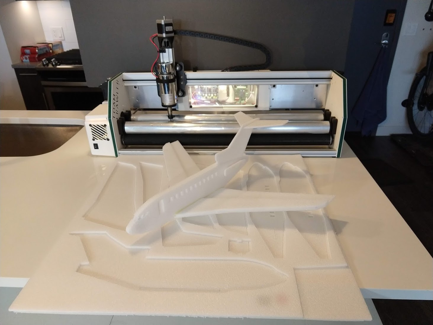
Dan cut some 727 gliders on the core crawler to test it out.
Above is a video of the Core Crawler CNC Machine being actuated and run. In the video the Core Crawler is cutting a simple example to demonstrate its basic capabilities. See the main Core Crawler page for further work on how the Core Crawler was designed, fabricated and built in its later versions.
CAD Files
 FoamCrawler CNC Onshape CAD Assembly Files
Future Opportunities
The Core Crawler can efficiently process thicker sheet material. This enables a variety of applications from tweaking different parameters.
Assembly:
- spooler would enable continuous sheet material processing
- additional DOF could enable 3d geometry (bending, origami, forming, singulation, etc.)
Toolhead / Applications:
- pen plotter for large media
- vinyl cutter for continuous flex circuits
- spindle for large molds
- adding indexing to roller for reel-to-reel processing
- adding features to roller for large format embossing