4. Computer controlled cutting
This week I worked on the computer controlled cutting assignments. I characterized our Fab Labs laser cutters. I deigned a parametrically adjustable press fit kit called Gator Cramz. I designed and vinyl cut my Fab Shop logo that representing my final project. I documented all my work extensively with text, photos, screen captures, and for the first time a YouTube video.
Group Assignment Link
Here is the link to our group assignment documentation: Computer Controlled Cutting
Assignment
| Have you? | Done |
|---|---|
| Group assignment: | ⬇ |
| Characterize your laser cutter’s focus, power, speed, rate, | Yes |
| kerf, joint clearance and types | Yes |
| Individual assignment: | ⬇ |
| cut something on the vinyl cutter | Yes |
| design, laser cut, and document a parametric construction kit, | Yes |
| accounting for the laser cutter kerf, | Yes |
| which can be assembled in multiple ways, | Yes |
| for extra credit include elements that aren’t flat | No |
Checklist
| Have you? | Done |
|---|---|
| linked to the group assignment page | Yes |
| Explained how you parametrically designed you files | Yes |
| Documented how you made your press-fit kit | Yes |
| Documented how you made your vinyl cutting | Yes |
| Included your hero shots | Yes |
Characteristics: MSI Fab Lab Laser Cutters
| Characteristic | Epilog Mini 24 #1 | Epilog Mini 24 #2 |
|---|---|---|
| Bed Size | 305 x 610 mm (12 x24”) | 305 x 610 mm( 12 x24”) |
| Focus | 50.8mm (2”) | 50.8mm (2”) |
| Power | 35 Watts | 35 Watts |
| Rate | 1778 mm/sec (70 ips) max | 1778 mm/sec (70 ips) max |
| Pulse | 100-5000Hz | 100-5000Hz |
| Kerf | 0.10-0.18 mm (.004-.007”) | 0.10-0.18 mm (.004-.007”) |
| Joint Clear | 0.25 mm (.010”) | 0.25 mm (.010”) |
Laser-able Materials
The most popular materials to laser cut in the MSI Fab Lab are the following:
1. 305 x 610 mm (12 x24”) sheets of 4mm thick cardboard with the specifications of:
ULINE (24 x 12”) 90 kg (200 lb) Corrugated Pads S-13742 4 mm (5/32”) thick C Flute
- 3mm thick cast acrylic from Inventables
Laser Focus
To review how focus works on the Epilog Legend Mini laser cutters I reviewed the user manual by searching and reviewing all the mentions of focus. It seems the focal length is based on the focal mirror spec 2” focal length lens are standard. With some plastic materials a de-focus can be used to improve cutting quality.
“Once you have the correct speed and power settings you can improve your engraving results even more by taking the focus lens out of focus (lower the table) by about 1/16 (1.5 mm) of an inch. This technique enlarges the focus beam a little bit and provides more beam overlap on each pass of the laser. The greater overlap produces a smoother engraved surface on the plastic and eliminates the grooves that you sometimes see when engraving plastic.” Page 119
“(Acrylic) Cutting Note: Adjusting the standard focus distance so it is closer to the lens by about .030” (.762 mm) will produce better edge quality on 1/4” acrylic and thicker. Two passes may produce better results and allow for cutting through thicker materials. There are two types of acrylic: cast is better for engraving (creates a frosted look when engraved) and extruded acrylics are better for smooth-edged cutting.” Page 143
Epilog also has a good Article called Focus Lens 101, which I read through. Of note was that a standard 2 inch lens “Produces spot size of 0.004 to 0.007 inches in diameter.” This leads into the topic of kerf.
Kerf
I remember having offsets of around .010 inch in acrylic, however today we’ll be working with cardboard so results may differ. I setup a series of squares in Inkscape. Of note while drawing these squares I noted the size of the selected object was always the line thickness bigger than the drawn size. For example a square drawn to 1x1” with a line thickness of .003” ended up being 1.003” when selected. Considering the laser beam width of .007 max, this .003” could throw off press fit fits. However upon closer inspection using View, Outline in Inkscape I realized that the line thickness in Inkscape is centered around the center of the line thickness, so this was an unfounded worry. Because of this for my experiments I labeled my squares with the drawn size, which should be accurate.
Joint Clearance
Given the above notes a joint clearance of between .007 min and .012 inches max due to laser heat affected zone may be expected. This means for perfect fit parts the offset may be in the range of .007 to .012 inches. I wonder if it is possible for some materials to swell back out after being cut as well.
1. I setup a 8x8” workspace in Inkscape via Menu: File, Document properties
2. Pressing Shift+Ctrl+F opens fill and stroke menu to set:
-Fill tab: No paint
-Stroke paint tab: Flat Color, RGB 0,0,0 A: 255 Opacity 100%
-Stroke style tab: width: 0.003 in (0.08 mm)
3. I drew 5 boxes across with varying decrease in size.
1.000, 0.993, 0.990, 0.988, 0.985 (25.40, 25.22, 25.15, 25.10, 25.02 mm)
 Above: 1.000, .993, .990, .988, and .985 boxes svg file ready for laser cutting
Kerf Width ULINE S-13742
My experiment was done cutting 305 x 610 mm (12 x24”) sheets of 4mm thick cardboard with the specifications of:
ULINE (24 x 12”) 90 kg (200 lb) Corrugated Pads S-13742 4 mm (5/32”) thick C Flute I used the MSI Fab Lab Epilog Mini 24 #1 laser cutter. Here is a chart of the results:
| Square Size | Inside Size | Outside Size | Difference inch | Difference mm |
|---|---|---|---|---|
| 1.000 | 0.997 | 1.004 | 0.007 | 0.18 |
| 0.993 | 0.997 | 0.990 | 0.007 | 0.18 |
| 0.990 | 0.988 | 0.995 | 0.007 | 0.18 |
| 0.988 | 0.986 | 0.990 | 0.004 | 0.10 |
| 0.985 | 0.980 | 0.988 | 0.008 | 0.20 |
It was very hard to measure the cardboard with a calipers. Also I wondered if the kerf angle would impact my measurements. The over all kerf width seemed to be 0.007 in the cardboard being used. So I decided to go with a 0.007 offset for one side of my parts when drawing in 3D CAD. This was a bit different than the .010 inch kerf width in acrylic.
Parametric Press-fit Kit
Using Onshape CAD I designed a triangular Gator Cramz barbed connection system. The idea is that you cram a serrated tooth into the gator mouth. The barbed nature of the serrations prevent the tooth from being pulled out. Once a Gator Cramz something in its mouth it does not let go! Onshape allows a parametric sketch offset function by selecting faces, which is hand for quickly generating offsets due to kerf loss. The values from the Joint Clearance section above were used to experiment with CAD interference fits to compensate for kerf and therefore result in slip to clearance fits when laser cutting. I will now run through the steps that I followed to generate my parametric Gator Cramz design.
Design Steps

Above: Sketch consisting of two rectangles on top of each other and two midpoint center-lines

Above: Close up of serrations, only one triangle serration was drawn, then the linear pattern tool was used to propagate the pattern along the angled line.

Above: Super close up of serrations sketch.

Above: Next to extrude the jaw by selecting the part of the Core Sketch highlighted in gold. Note specific selections in the Extrude Jaw window.

Above: Now to extrude the Ref Tooth by selecting the part of the Core Sketch highlighted in gray. Note specific selections in the Extrude Jaw window, this extrude requires selecting all the tiny serration faces of the sketch.

Above: Mirroring the Jaw by selecting the left gold jaw section and then the right plane from the features tree on the left. Boom mirror ya! Note “Add” tab selection in Mirror sub window.

Above: Mirroring the Ref Tooth by selecting the left gray tooth section and then the right plane from the features tree on the left. Boom mirror two!

Above: Creating an offset sketch by selecting the face of the top face of the tooth, then selecting the offset icon. Here I am offsetting by 0.007 inches. But this value can be changed easily later. Sweeeeeet Parametrics!

Above: Zoom in on offset sketch, note gray reference dimension set at 0.007 inches

Above: Isometric view of completed 3 parts. A PDF 2D drawing at 1:1 scale will be created in Onshape for import into Inkscape so we can set the correct line thickness for cutting and do layout.

Above: Zoom in on Real Tooth (Part 3 in tree and shaded blue) showing part transparency at A 0.84 so we can see the 0.007 inch offset edge clearly. Part transparency options is one of my favorite tools in a CAD system.

Above: Click the gray + in the lower left and then select create a drawing.

Above: insert the jaw parts in top view with a scale of 1:1

Above: if you forget to set the scale you can set the sheet scale by right clicking Sheet 1 in the Sheets tree menu on the left. See the Sheet Properties window here for settings you need. You may want to select a smaller or bigger Size, here we have selected A size.

Above: I like to delete all the title block lines so the pdf file is smaller and faster when we export.

Above: Adding dimensions is optional, but can be a helpful reference for double checking dimensions in Inkscape.

Above: Now we can right click the Drawing 1 tab and select export.

Above: We want Format PDF, Options Download. I’d suggest matching the other settings as well. now click export.
Above: Here is the Onshape drawing PDF imported into Inkscape.
Laser Cut

We have a 40 watt Epilog Mini Laser Cutter

Here are the settings used to cut the cardboard.

The laser cutting!

The results!
Parametric Construction Kit
With everything tested out in cardboard I moved on to making my Gator Cramz construction kit. I added parametric hexagon features to the mouth and jaw parts.
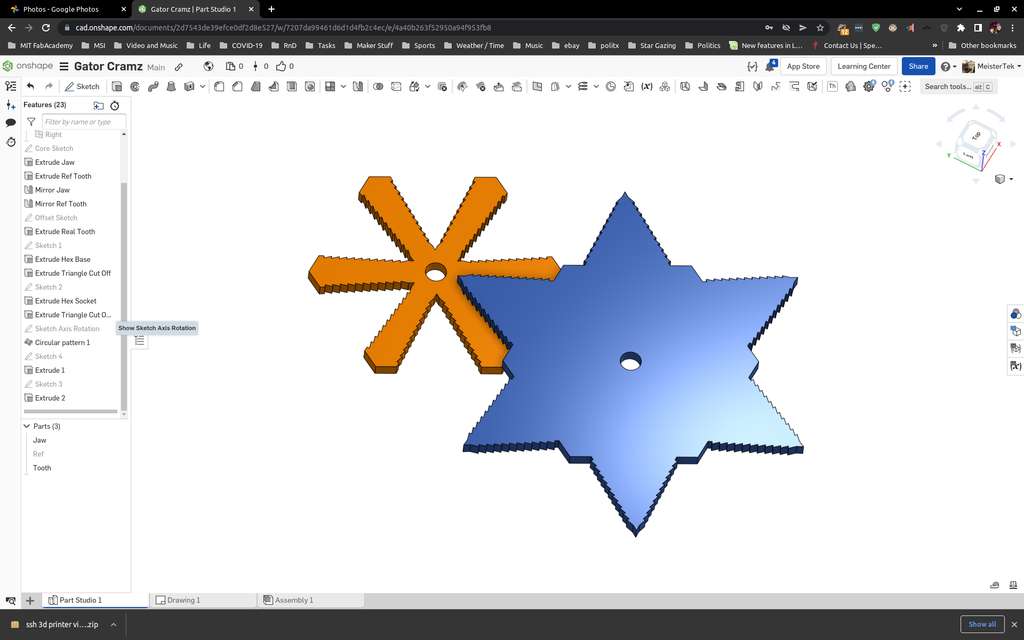
Left: mouth geometry parametrically rotated 6 times around a hex. Right: tooth geometry parametrically rotated 6 times around a hex.
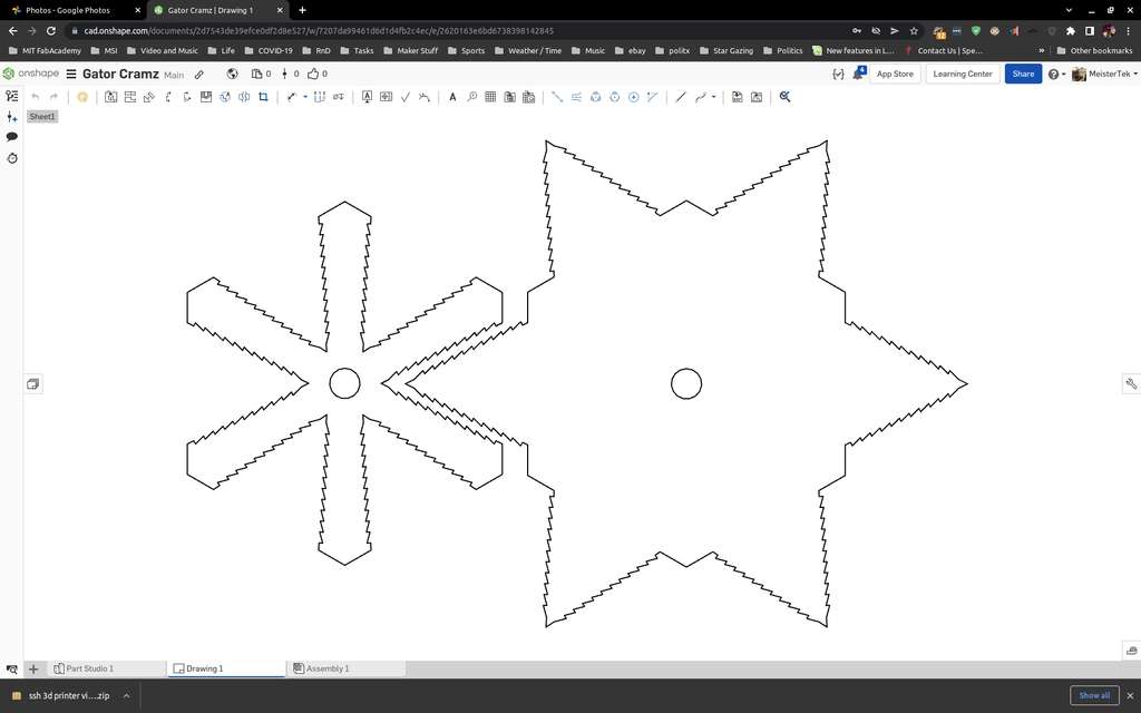
construction kit parts added 1:1 sacle to an onshape drawing. This drawing was exported as a PDF for laser cutting after some prep work in inkscape.
Next I moved on to cutting on the Epilog Mini 12x24 laser cutter.
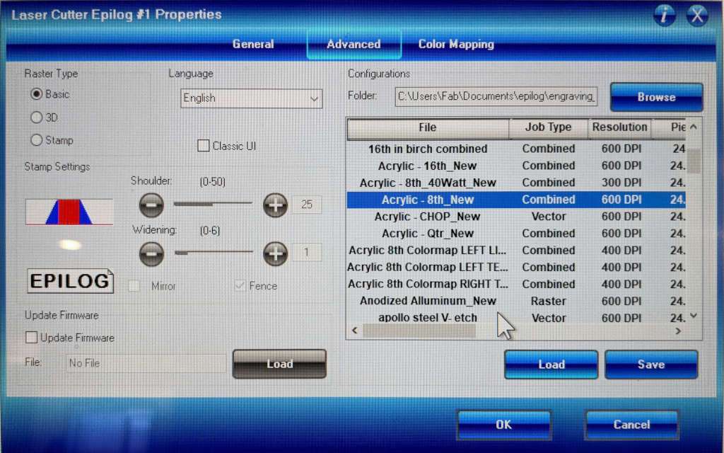
1/8” acrylic settings 1
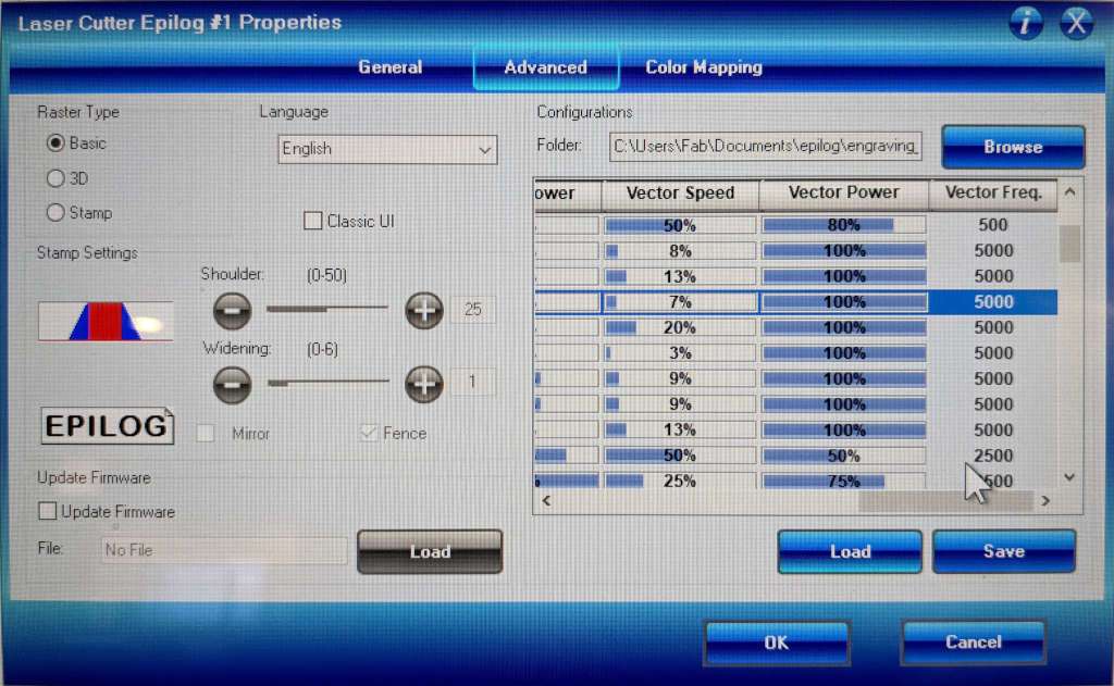
1/8” acrylic settings 2
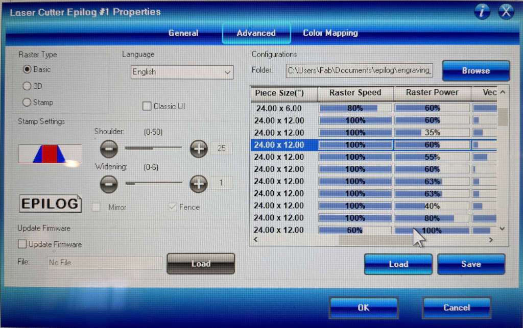
1/8” acrylic settings 3
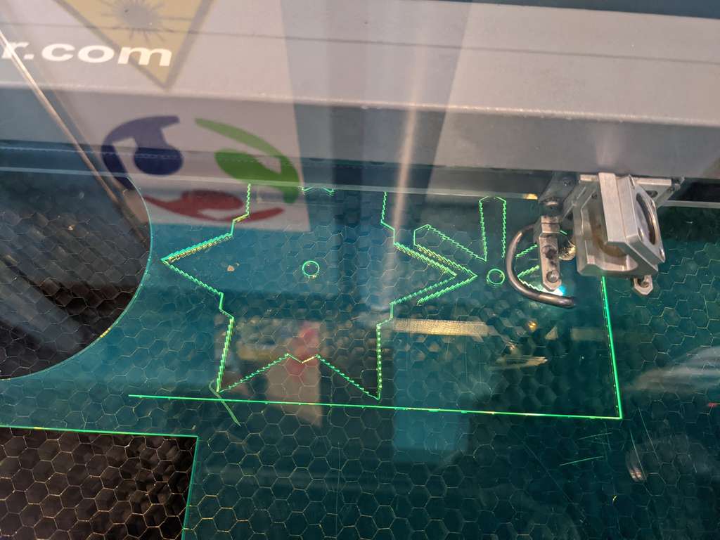
Parts being laser cut
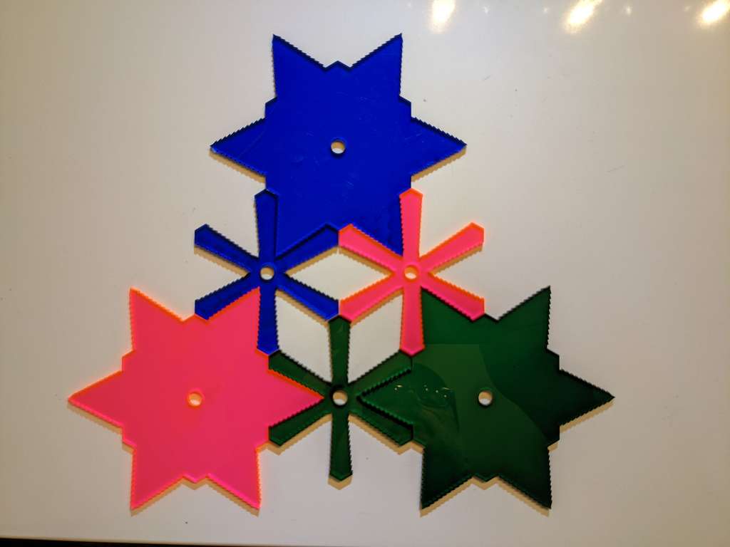
Finished parts press fit together with a slight creaking sound and then hold in place.
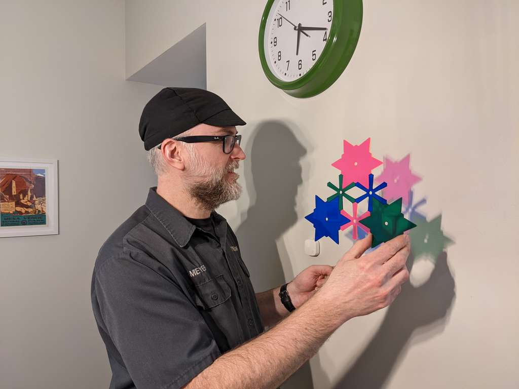
I cut my construction kit from transparent acrylic, the shadows cast are cool looking. And the press fir holds up well.
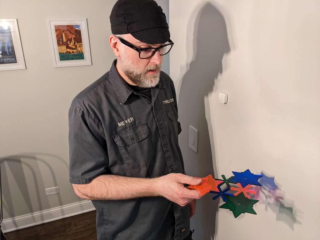
Much to my surprise, the parts hold together cantilevered horizontally. If you know your laser cutters characteristics, amazing press fit parts are possible. I was surprised that these acrylic parts didn’t crack and held in place in two dimensions so well.
Vinyl Cut something
Fab Shop Logo
Industrial Design and CAD
I decide to design and a Fab Shop Chicago Logo to represent my final project. The first iteration of the logo will be vinyl cut, later iterations will be digitally embroidered patches. I designed the logo in Inkscape.
Here are some notes on my design and planning process. I want to have design continuity with the local Chicago flag and local hackerspace logos.
Chicago Flag Reference
South Side Hackerspace Chicago Branding Standards
Pumping Station: One Hackerspace logo origins
The DIN 1451 Font SIL Open Font License (OFL) is very close to the font used for text in the South Side Hackerspace: Chicago logo and also with Pumping Station: One logos. This is the font I will use.
I read through the Flag of Chicago Wikipedia entry to learn more about its history.
Three gears, equal 3 machines. A gear may be added to the logo for each machine you have built. FAB = made in a Fab Lab and Chicago’s industrial roots with fabrication shops and capability. Shop is a nod to Chicago Fabrication and job shops. Single Chicago star connects to Chicago and makes for a good triangular logo sleeve patch.
Here are photos of the various design decisions made moving forward to the final logo.


Vinyl Cutting CAM Process
I have a old Silhouette SD vinyl cutter at home. I wanted to use it without using a proprietary windows os, so I found the fablabnbg inkscape-silhouette extension for inkscape. I used the following online tutorials to help get it installed and running.
Please note that the inkscape-silhouette extension works well with Inkscape 0.92.5. At this time it does not work well with Inkscape 1.0 or above, due to program changes. Well it does work, it’s just that scale is off, cutting much smaller in size than you intend. There is a ticket submitted and coders are needed to update inkscape-silhouette to work with 1.0 and above.
fablabnbg/inkscape-silhouette extension on GitHub
I used a clear cutting mat with pen plotted backer to allow the use of very small pieces of scrap vinyl to be used to cut my Fab Shop Logos. This process allows for the use of vinyl that is often discarded at fab labs, makerspaces and hackerspaces.
I documented this Scrap CAM Vinyl Cutting process that I developed in the following video:
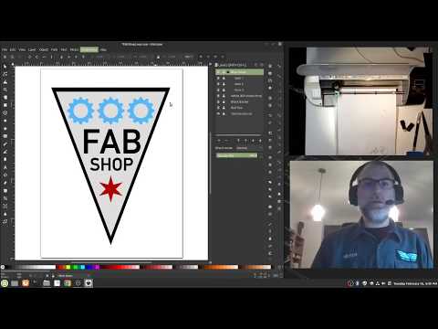
The video above was made using two open source software packages. Open Broadcast Studio was used to produce a video with two live cameras and one screen capture. I then used kdenlive to edit the video, covert it to mp4, compress it and upload it to YouTube. The video is 17 minutes and 64MB so it was too big to upload to my repo. Even after running Neil’s compression command for variable bit rate 1080p MP3 the video was still too large to upload.
Repo video
In case the link above gets broken I edited the long video above down into it’s main points and highlights of cutting, weeding and placement:
Hero Shots
Vinyl Cut Fab Shop Stickers

Native CAD Files
Gator Cramz: onshape cloud link
Gator Cramz: Parasolid file (1.2MB uncompressed, 290.6kB zipped)
LaserKerfDmeyer.svg: Inkscape SVG File
Fab Shop Logo: Inkscape SVG file