3. Computer Aided design
Assignment
Model (raster, vector, 2D, 3D, render, animate, simulate, …) a possible final project, compress your images and videos, and post it on your class page
Evaluate and select 2D and 3D software
Demonstrate and describe processes used in modeling with 2D and 3D software
Checklist
| Have you? | Done |
|---|---|
| Modeled experimental objects/part of a possible project in 2D and 3D software | Yes |
| Shown how you did it with words/images/screenshots | Yes |
| Included your original design files | Yes |
Possible Final Project
During this assignment I worked on using CAD to communicate my Fab Shop Lathe/Mill possible final project idea. The Lathe/Mill that will be one of 3 machines for my Fab Shop a long term concept project I will be working on over the next several years.
| Process | Diameter | Length | Width | Height |
|---|---|---|---|---|
| Turning | 26 mm | 100 mm | NA | NA |
| Milling | NA | 80 mm | 80 mm | 80 mm |
I used the following types of graphics software to communicate my concept.
Raster CAD
Scan Hand Sketch
I scanned a hand drawn sketch of my Fab Shop Lathe/Mill concept
 I compressed this image by scaling from my cell phones native camera resolution of 4032 pixels wide down to 600 pixels wide in Gimp. Next I exported the image from gimp and selected 60 compression before saving the file. The reduced my image file size from 2MB down to 35kB. Wow that an amazing reduction in file size!
Gimp
I then used this scan in gimp as a reference to create a 2D CAD drawing.
I used the rectangle select tool and then color coded blocks representing different parts of the machine.
 What was interesting about using gimp as a CAD tool was that it wasn’t as terrible as I first thought. Masking squares and coloring them in was pretty easy. Also the layer control allowed me to hide and reveal parts of the drawing.
Here is the native gimp xcf file: Sci_Center_MT.xcf
What was interesting about using gimp as a CAD tool was that it wasn’t as terrible as I first thought. Masking squares and coloring them in was pretty easy. Also the layer control allowed me to hide and reveal parts of the drawing.
Here is the native gimp xcf file: Sci_Center_MT.xcf
Vector CAD
Inkscape
Next I used Inkscape. This was even better since I could have machine components in layers and easily change the layers from background to foreground. Also rectangles could be grouped and moved around easily even after drawing. Align and distribute was quite useful as well. Path boolean operations like Union were quite useful. Duplicate was used to make 2x motors. Changes were quicker. Transparency allowed buried parts to be partially visible. Arrows were much easier to draw using lines and adding arrows to their end in the Command Fill and Stroke (Shift+Ctrl+F), Stroke Style (tab), Markers. The image below is a Inkscape native SVG file, so it can be downloaded in native format via a right click, save image as.

Onshape
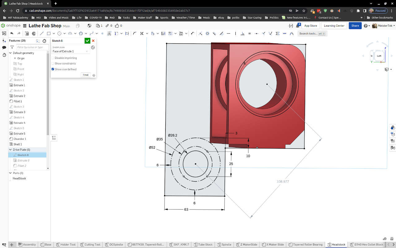
Then I 3D modeled the lathe in onshape CAD.
Parametric Sketches
I used Parametric sketches to control the location and sizing of the parts, to control components distances away from wall. Allowing space for covers was also added to Parametric sketches. Constraints were also added to sketches and all sketches were fully constrained.
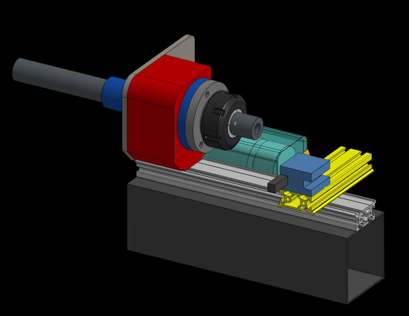
3D CAD
Onshape allowed me to get a much better understanding of what kinds of clearances between custom and stock components was needed. This allowed me to optimize parts for the machining envelope I wanted. Here is a
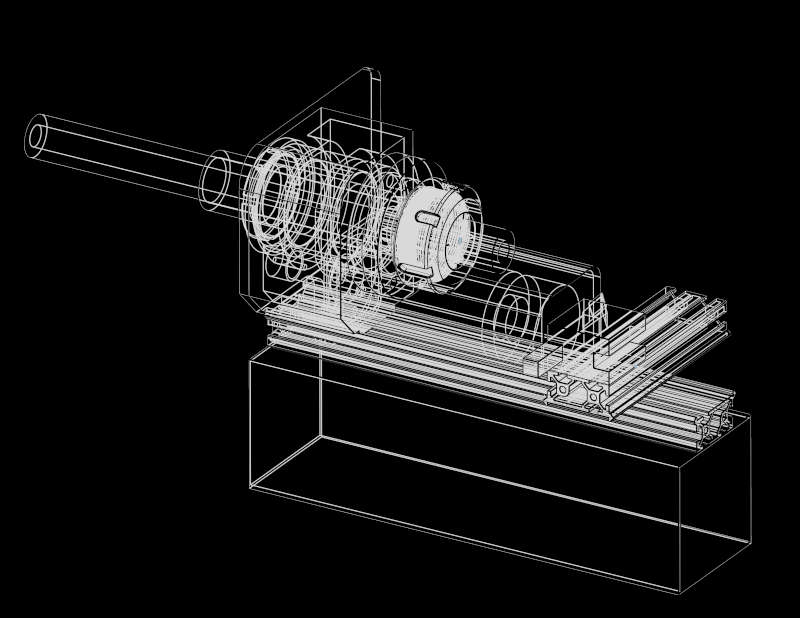
 Wire frame view
Native onshape file
The onshape file is at this link: Lathe Fab Shop
Simulation
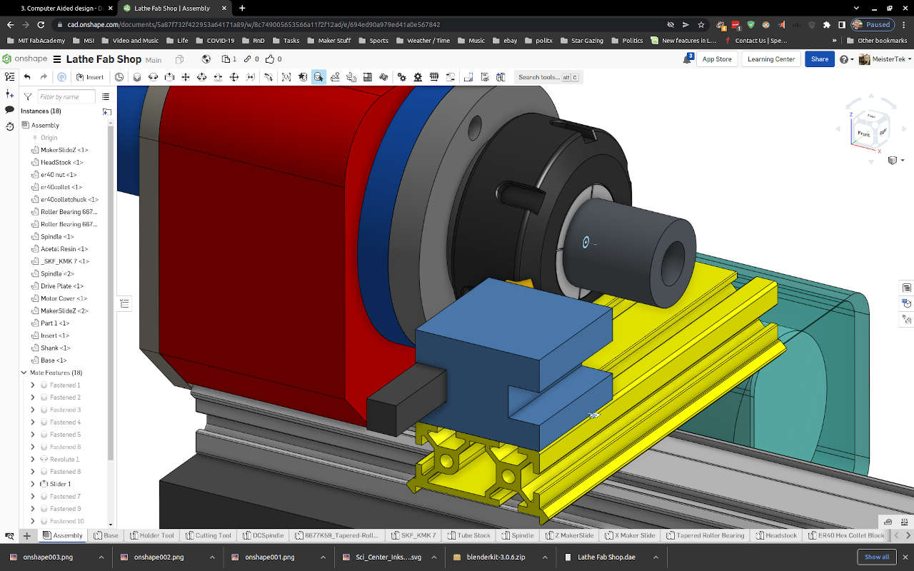
Using assembly mates in onshape allowed me to simulate the movement of the lathe parts.
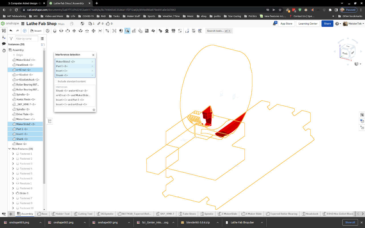
Interference Simulation
The Interference view in onshape allowed me to see if parts were crashing together.
Animation
Assembly Mates
Onshape does not have a built in recording function, Onshape suggest using a screen capture software to record animations. I used OBS software to screen capture my Onshape animations. This video shows the animate function of onshape for several different assembly mates.
Render
Appleseed (Fail)
Appleseed is an open source rendering package.
To run applesee on my Linux Mint OS, I downloaded, un-zipped and ran appleseed per the getting started section on the site above.
The first time I ran ./appleseed.studio the following error appeared:
./appleseed.studio: error while loading shared libraries: libpython2.7.so.1.0: cannot open shared object file: No such file or directory
So I decided to make sure libpython2.7 was installed by running this command from the terminal:
sudo apt-get install libpython2.7
Libpython installed.
However after several hours of searching I could not find documentation on how to easily use Appleseed. Time to move on.
Blender
Next I tried Blender.
To install I visited Blender 3.0 Reference Manual. I decided to use snap to install Blender on my Linux Mint OS. I use the guide here: Installing on Linux.
Next I exported my Lathe for Onshape as a Collada (.dae) file and imported the file into Blender. I used this video guide to get started with rendering: Blender 3.0 Beginner Rendering Tutorial (Donut part 6).
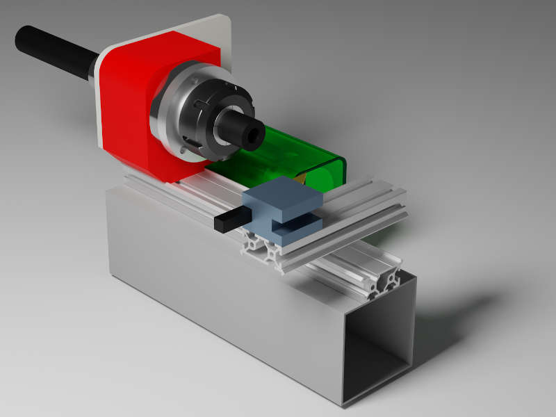
My first two renders were using Eevee Rendering Engine


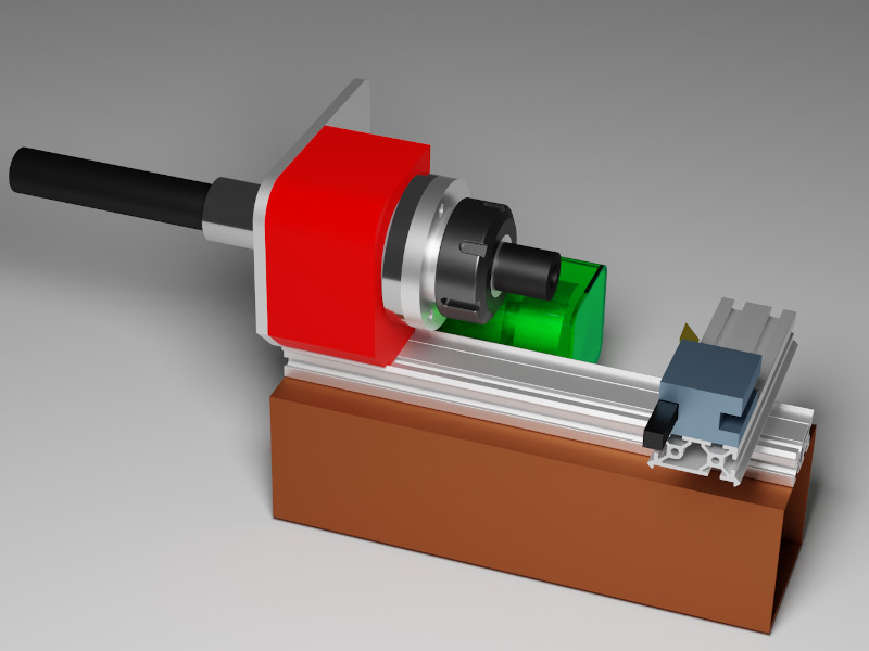
My third render was using Cycles Rendering, which took longer but looked more realistic, especially shadows.

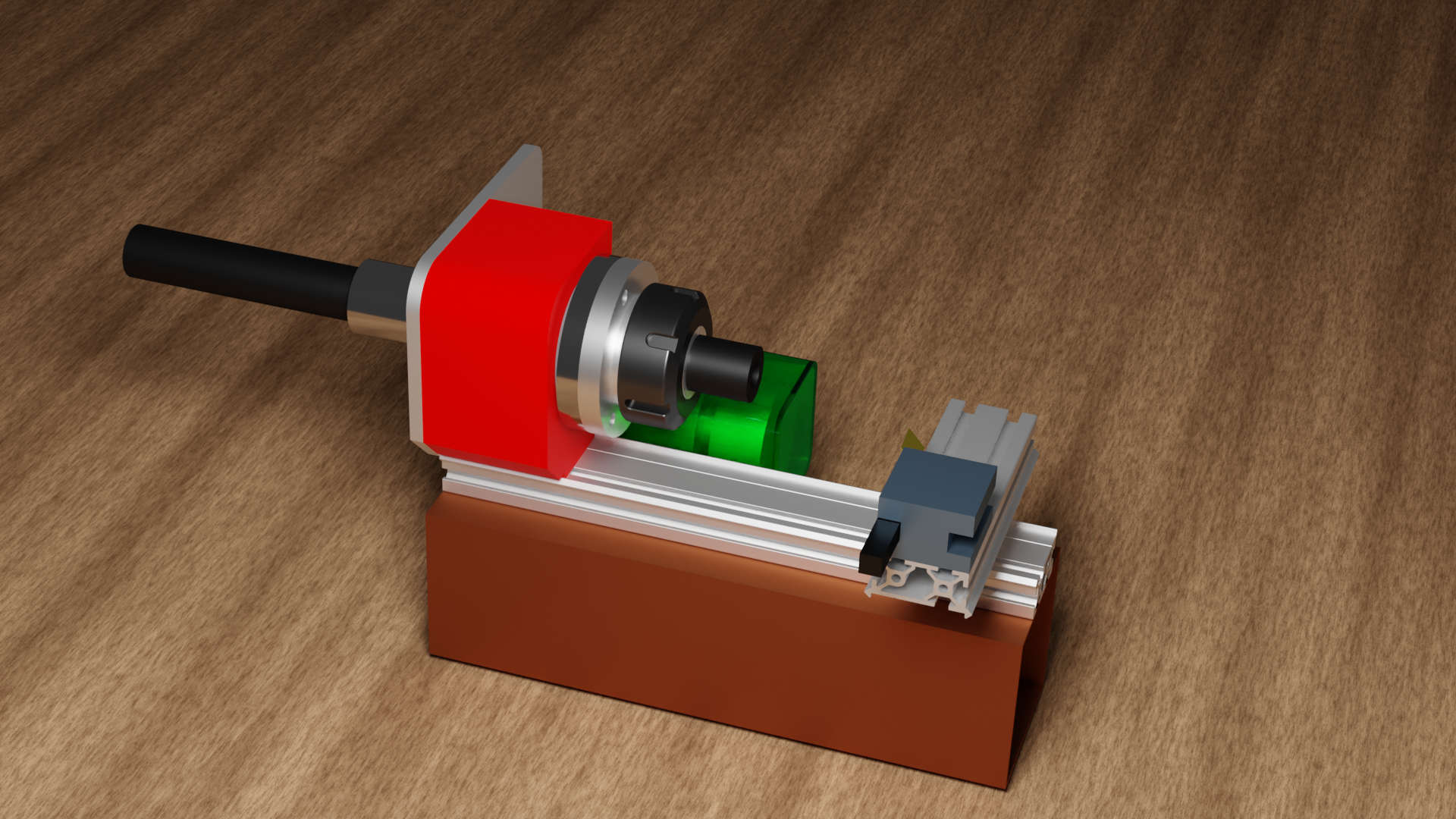
I eventually learned enough to turn up metallic and turn down roughness variables from .5 to 4 to get more realistic looking metal parts on the lathe. I continued tweaking. I also learned how to make a green transparent plastic material for the motor cover!
 Next I moved the render camera view point to different perspective. I also added a rust color to the steel base of the lathe.
 Finally I activated the Blender materials vx add in. This add in had a wood grain material I added to the floor.
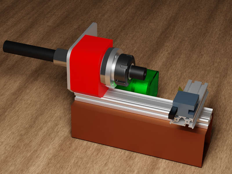 Here is a full resolution image of my final render. I used gimp to export this image with 60 quality and a very small size of 198.5kB with very little visible quality reduction.
 Full Size Image
Native Files
2D Hand Sketch (.jpg 34.7 kB) Gimp Raster (.xcf 67.5 kB) Inkscape Vector (.svg 08.5 kB) Onshape 3D Parametric CAd (direct cloud link) OnShape Export Parasolid (Zip compressed .x_t 401.2 kB 1.3 MB uncompressed) OnShape Export STEP (Zip compressed .step 244.1 kB 1.5 MB uncompressed) Blender (.blend 2.1 MB zip compressed 7.2MB uncompressed) Render Medium Res (.jpg 184kB)