11. Output devices
Individual Assignment
- Measure the power consumption of an output device
- Document to reflect your learning
- Add an output device to a microcontroller board of your design.
- Program the output device to do something
Group Assignment
Incite Focus Outputs Group Assignment
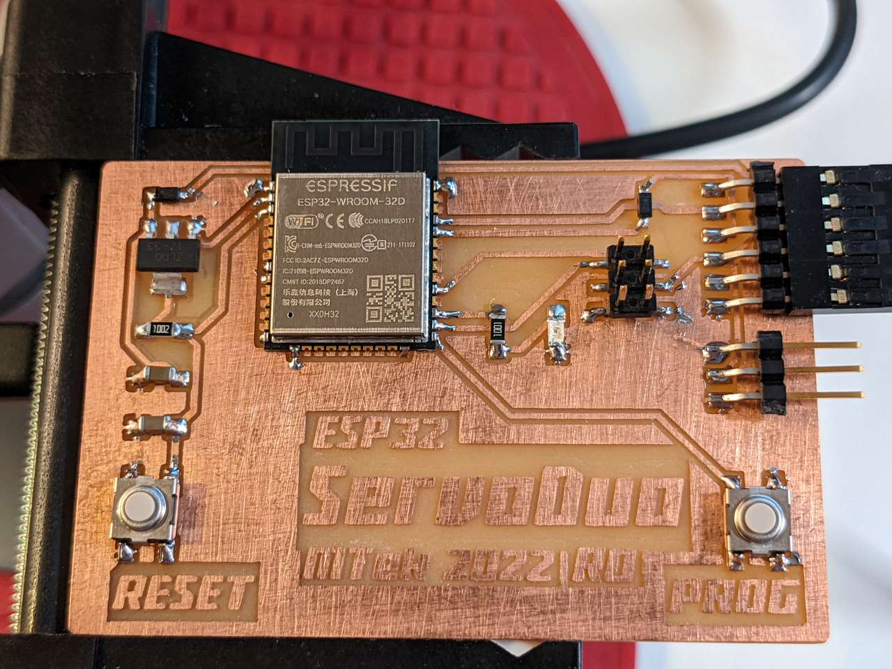
ServoDuo
I decide to make a board that outputs pulses to control 2 hobby servos, hence ServoDuo is the name chosen!
Measure Power
How much power is drawn when the servos are actuated. This will be somewhat difficult to measure, but I have some specialized tools to help me: The ToolkitRC ST8 Servo Tester The ST8 will allow me to see the current draw of my chosen servos displaying a current curve. I do know from experience that servos and motors can draw so much current they’ll brown out a microcontroller. It’s always best to power servos on their positive lead with a separate 5VDC rail that does not pass through the microcontroller at all. The PWM pulse like servo positioning signals are the only thing that should pass though the microcontroller. Common ground traces must be thick and also should lead directly to the 5VDC power source.
Let’s setup the ST8 Servo Tester and see what kind of power curves we get! All servo testing was performed at 5.0VDC and an output of 20.0ms/50Hz.
HiTec HS-422 Analog Servo
The HiTec HS-422 is a standard size analog servo with plastic gears. This servo if popular in robotics projects and medium sized radio control aircraft and cars. HiTec has excellent customer service and documentation of their servos. Here is the useful HiTec General Servo Information.
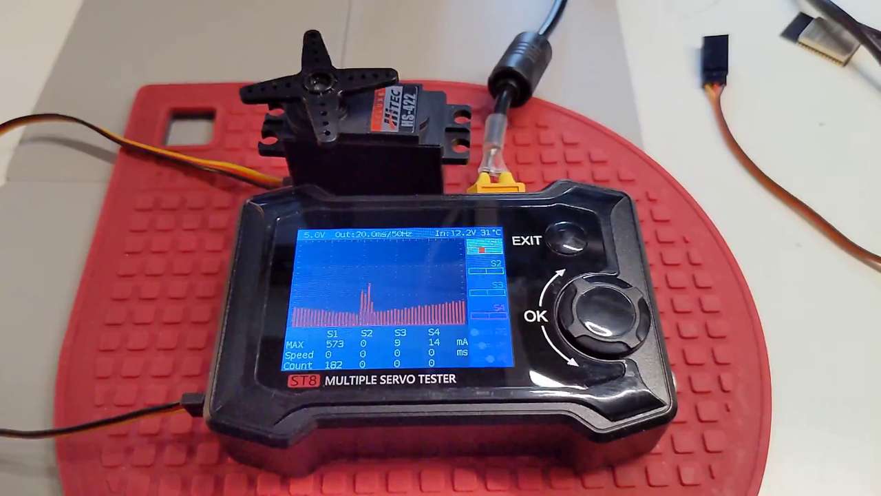 Above: The sweep command of the servo is at a medium speed with a linear setting and a step 1us and speed 1ms. The max current draw is 573mA (2.865 watts).
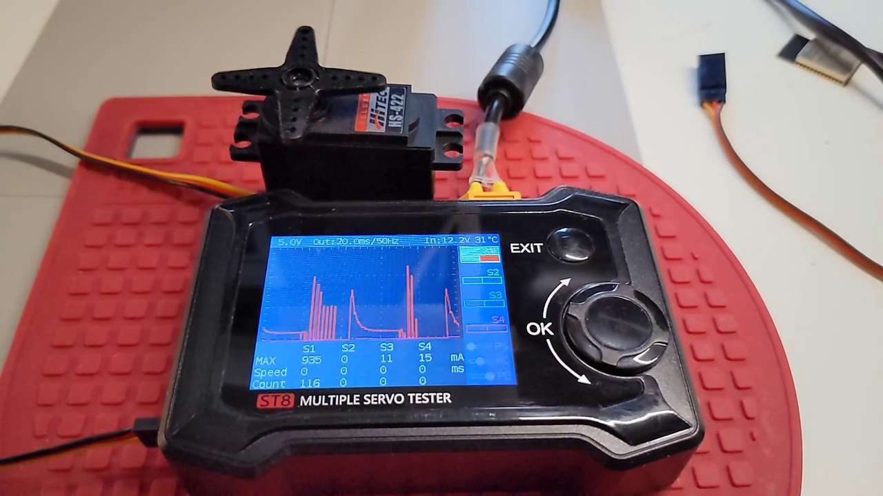 Above: The sweep command of the servo is at max pulse speed with a stage setting and Freq of 1Hz the max current draw is 935mA (4.675 watts). This is the fastest servo movement possible. I would need to test more servos, but it looks like HiTec’s specs are off by 135mA compared to stall current specs.
Corona DS-239MG Digital Servo
The Corona DS-239MG is a thin wing digital servo with metal gears. This servo is used mainly in small radio control gliders with thin wings and large control surfaces. Corona has limited documentation but it is sufficient.
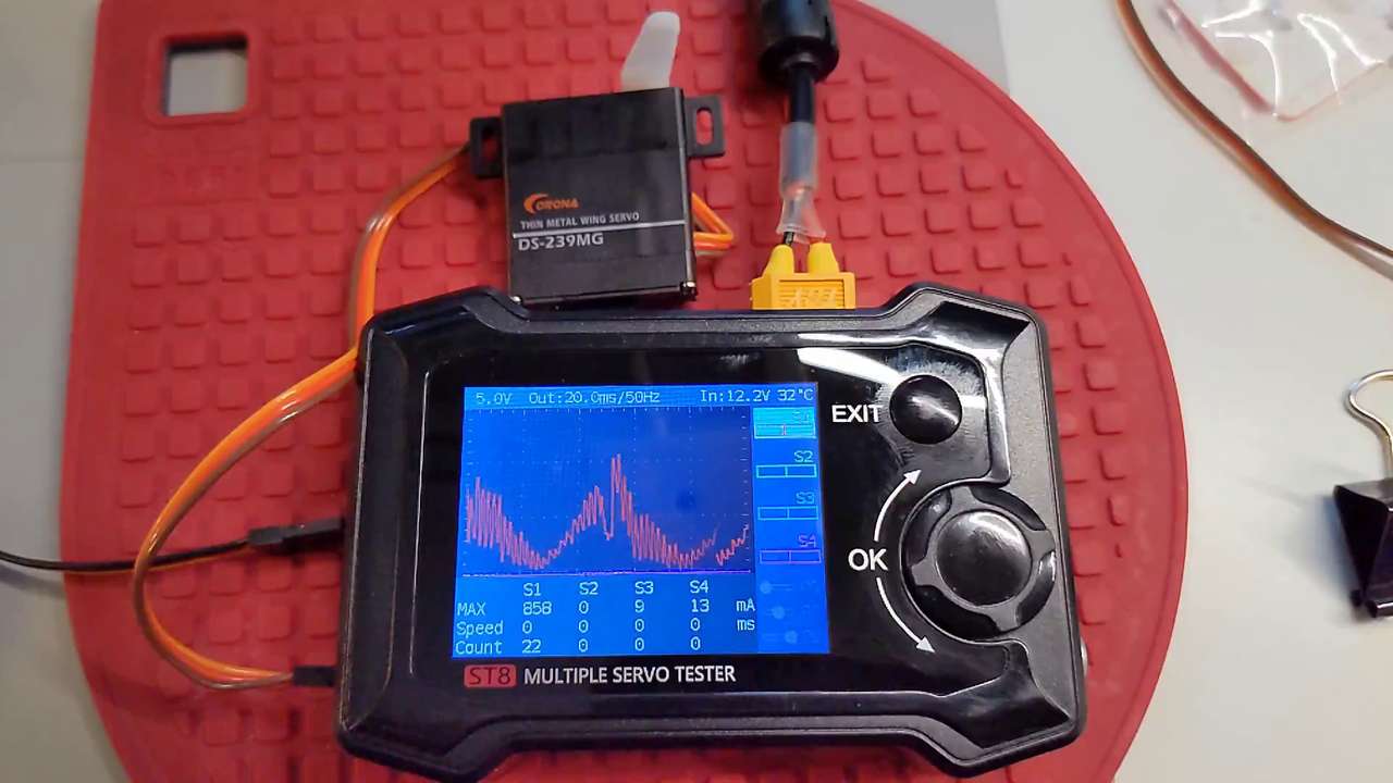 Above: The sweep command of the servo is at a medium speed with a linear setting and a step 1us and speed 1ms. The max current draw is 858mA (4.29 watts).
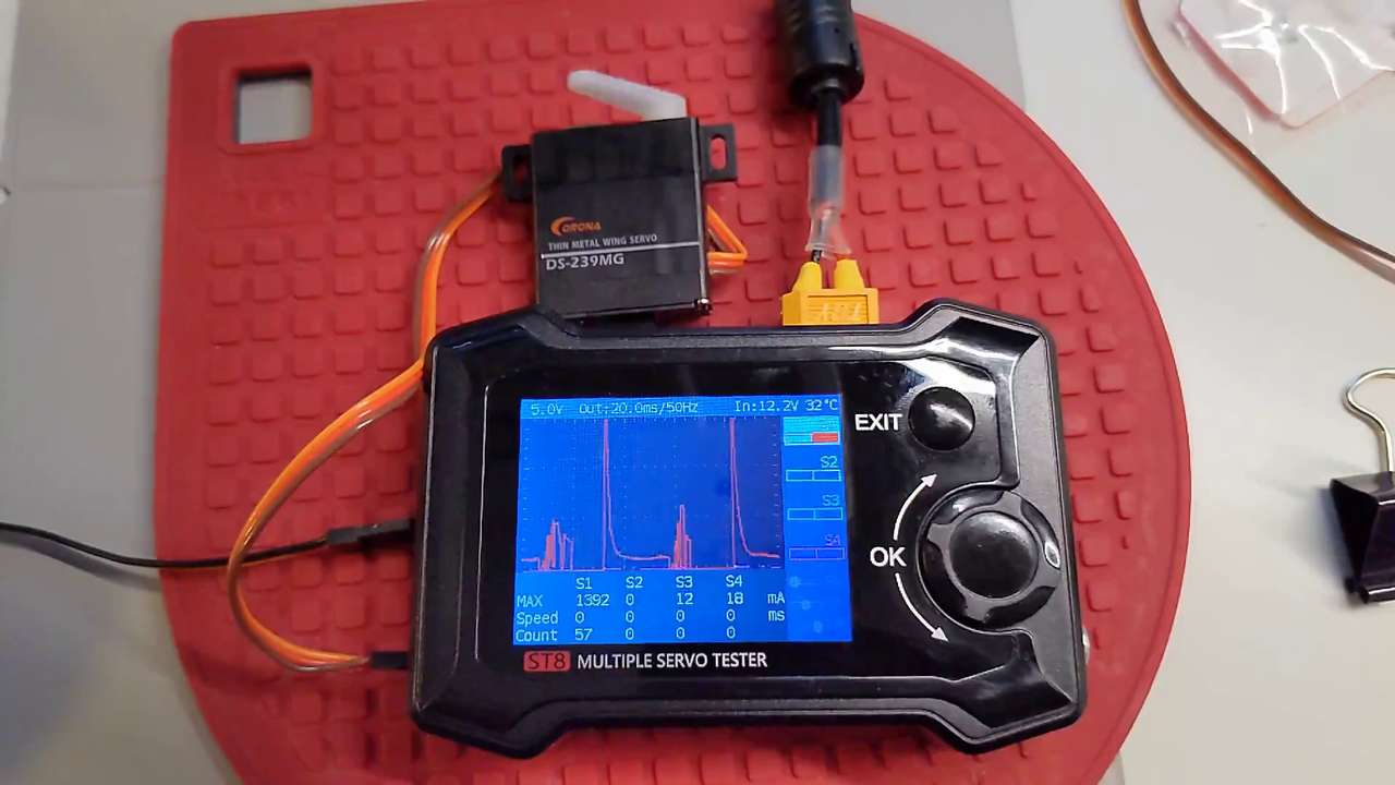 Above: The sweep command of the servo is at max pulse speed with a stage setting and Freq of 1Hz the max current draw is 1.392A (6.96 watts)! I would need to test more servos, but it looks like Corona’s specs are way off on current draw for this servo! Corona has the current specified at: 300mA
Servo power summary
As can be seen just one servo can draw quite a bit of current, especially when commanded with a flinch reaction move from dead a start. For example the 1.3A draw of the digital servo is normal and very often an RC aircraft will have up to 8 of these servos and a total peak potential current draw of 10 Amps (50 watts)! This is why others and myself suggest: ALWAYS POWER SERVOS DIRECTLY FROM HIGH CURRENT BATTERY or DC SOURCE. Do not send power for servos through thin traces or microcontrollers. The signal to the servo of course can be routed to a microcontroller and through thin traces. Grounds should be common. Grounds to the servo should be direct or on a thick trace.
Batteries to power servos
Sanyo Eneloop NiMH AA batteries with a nominal voltage of 1.2VDC are one of my favorite power sources. For small robots running up to a total of four hobby servos I highly recommend a pack of 4 Sanyo Eneloop NiMH AA cells in a battery holder with the cells in series for a nominal 4.8VDC. For high performance RC Aircraft it’s best to power your servos with a high quality Battery Eliminator Circuit (BEC) running off a high current LiPo flight or separate battery pack.
EDA
 Above: KiCAD Schematic in SVG format, file size is still quite small, but easy to read if zoomed in on!
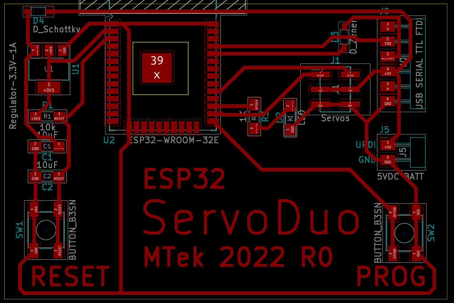 Above: KiCAD PCB Editor with traces routed
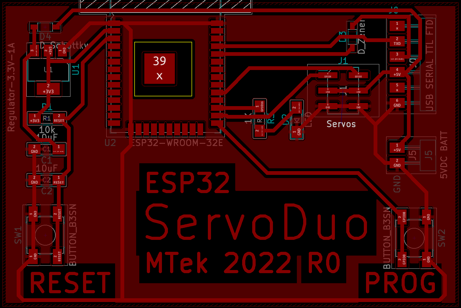 Above: Ground Pour added!
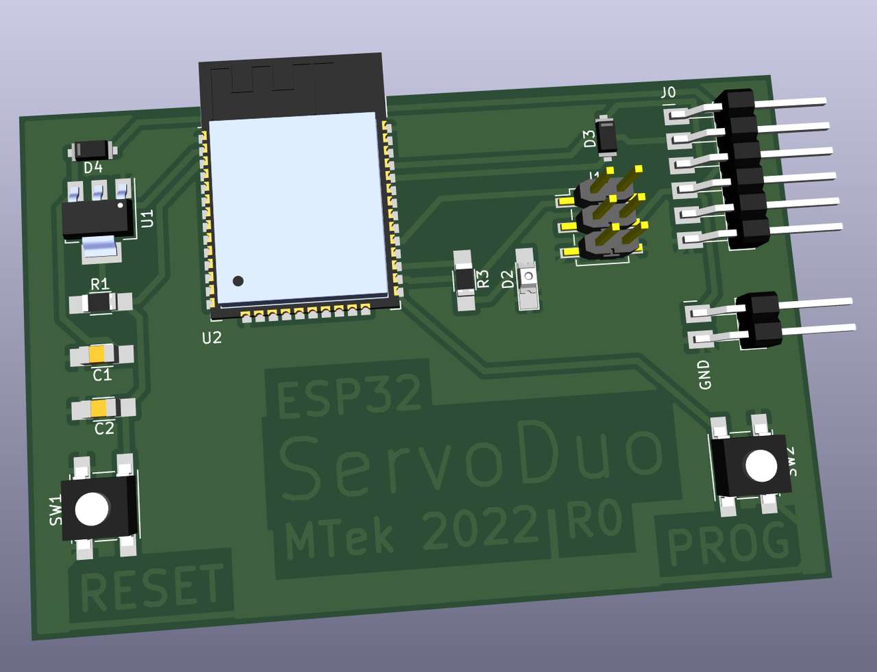 Above: KiCAD 3D View!
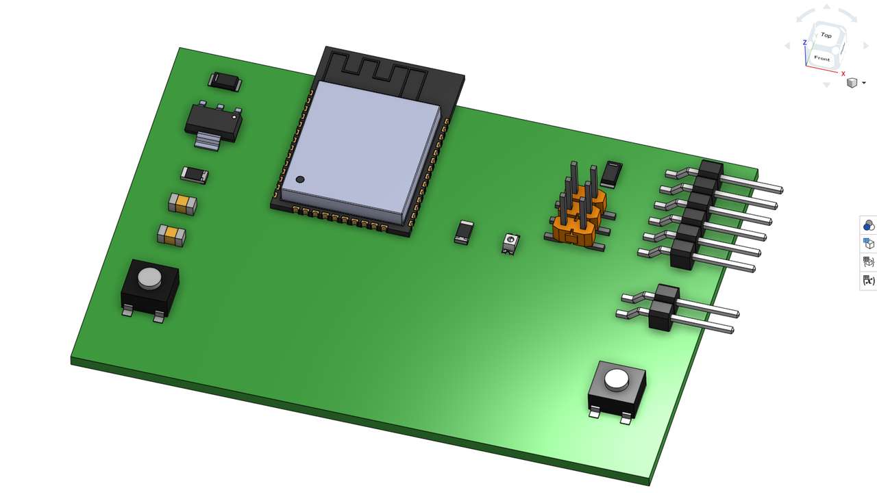 Above: KiCAD 3D imported via STEP file into onshape CAD.
 Above: SVG as exported from KiCAD and imported into inkscape. Note the messy state of the traces.
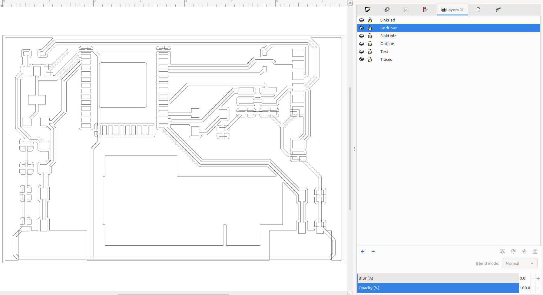 Layers set to speed cleanup
 Cleaning up the traces.
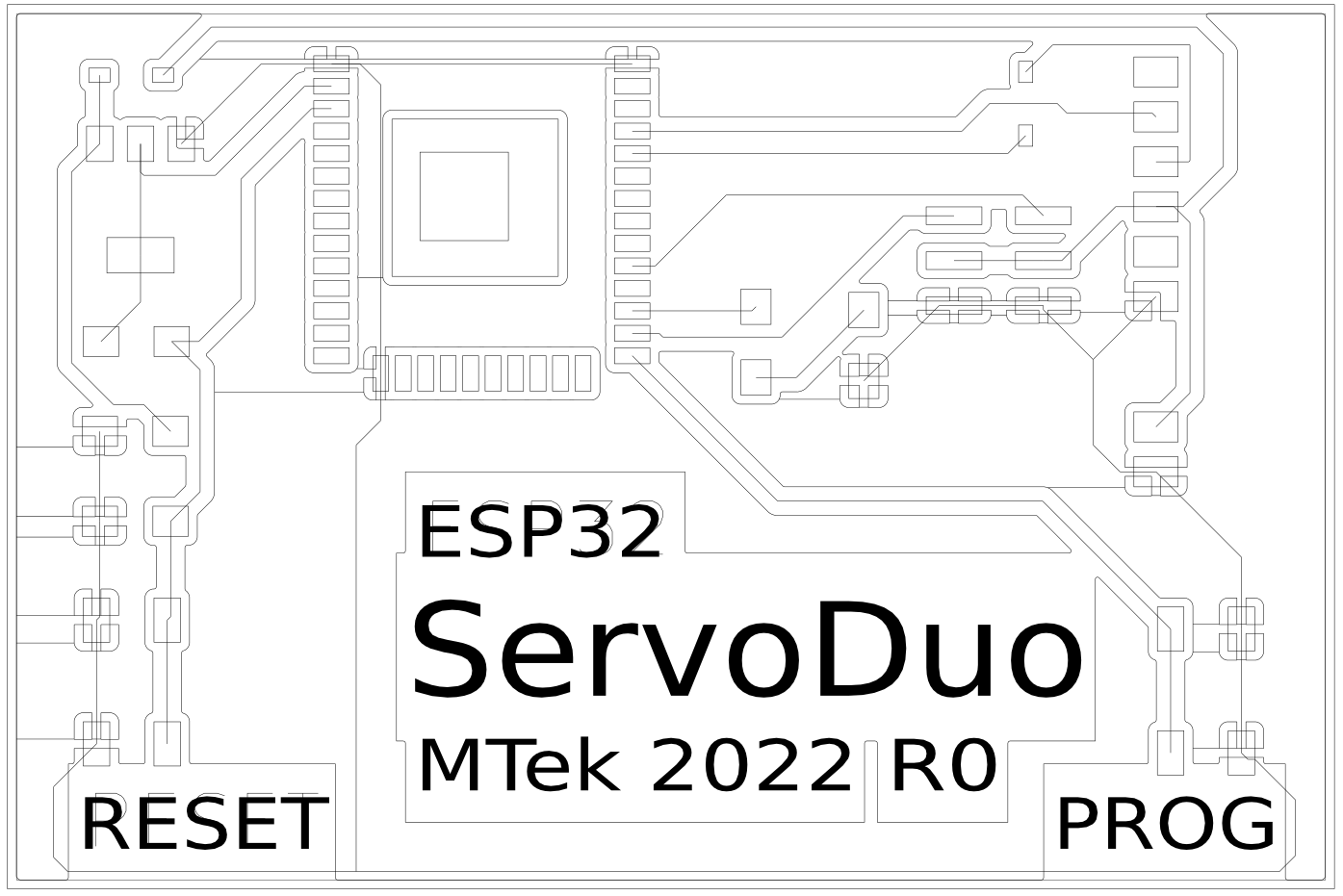
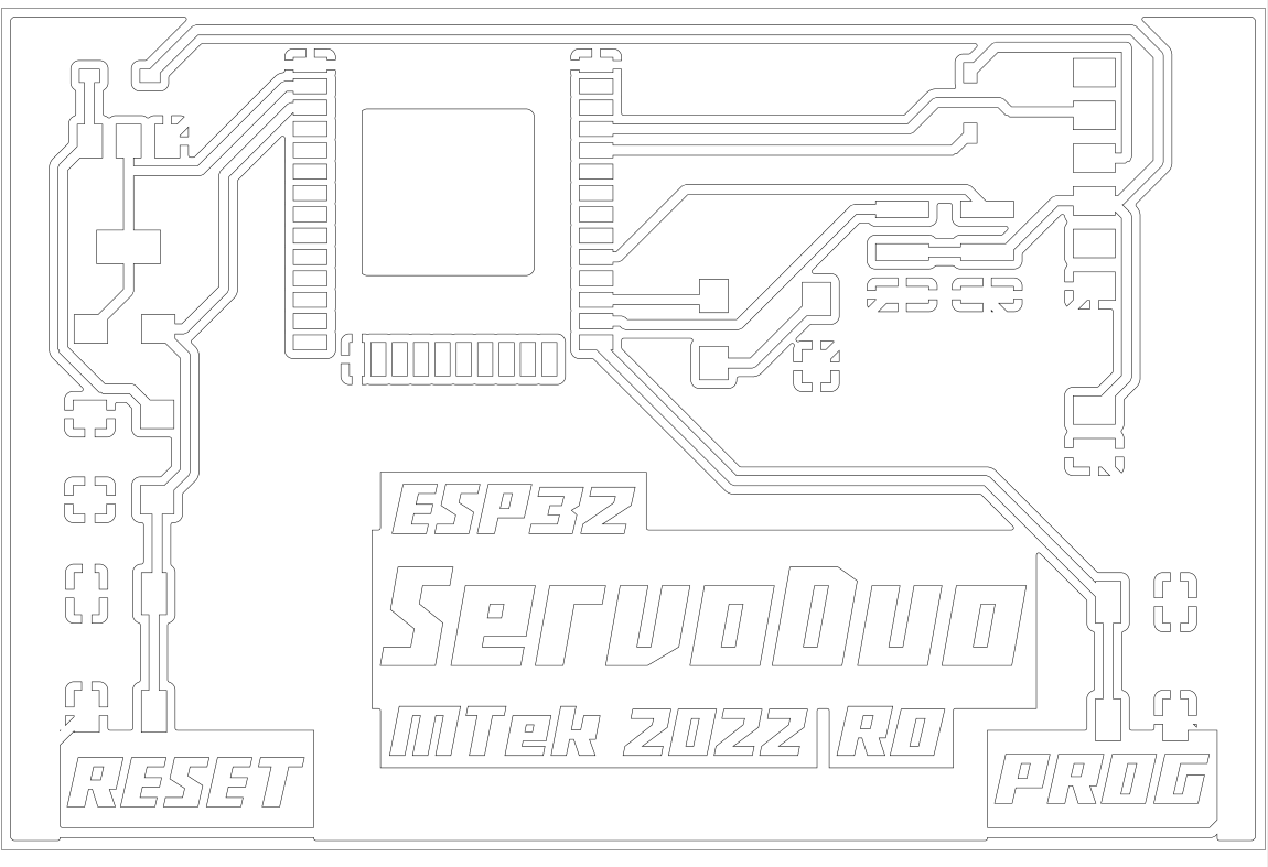 Traces cleaned and joined, custom font text added.
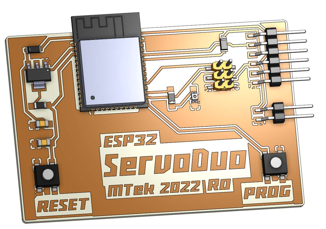 Wow! the addition of the graphic design work in inkscape imported as a dxf and extruded in onshape looks awesome! Stuffing will be easy with the realistic image!
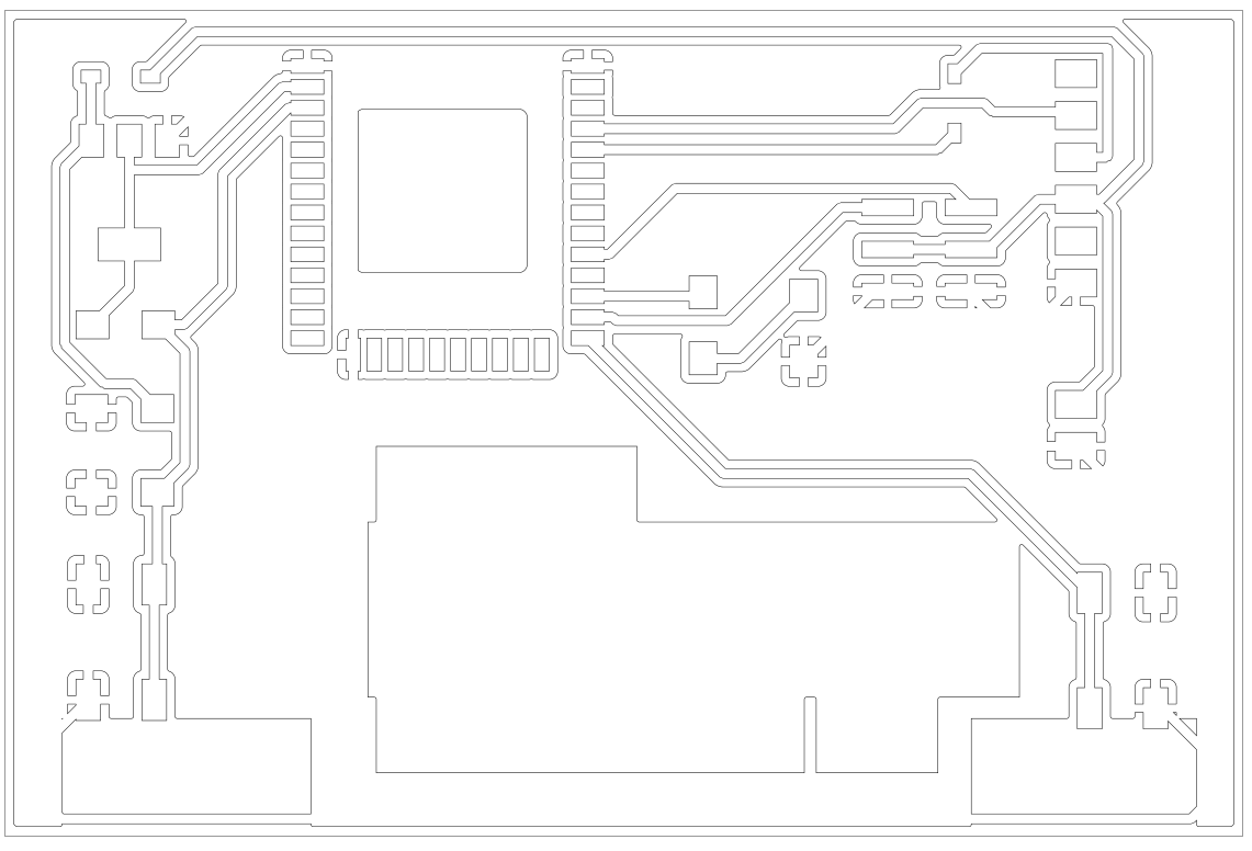
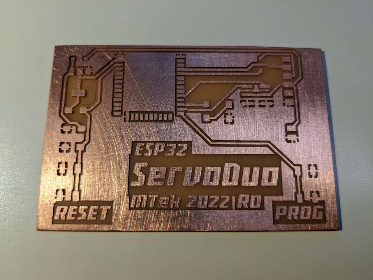
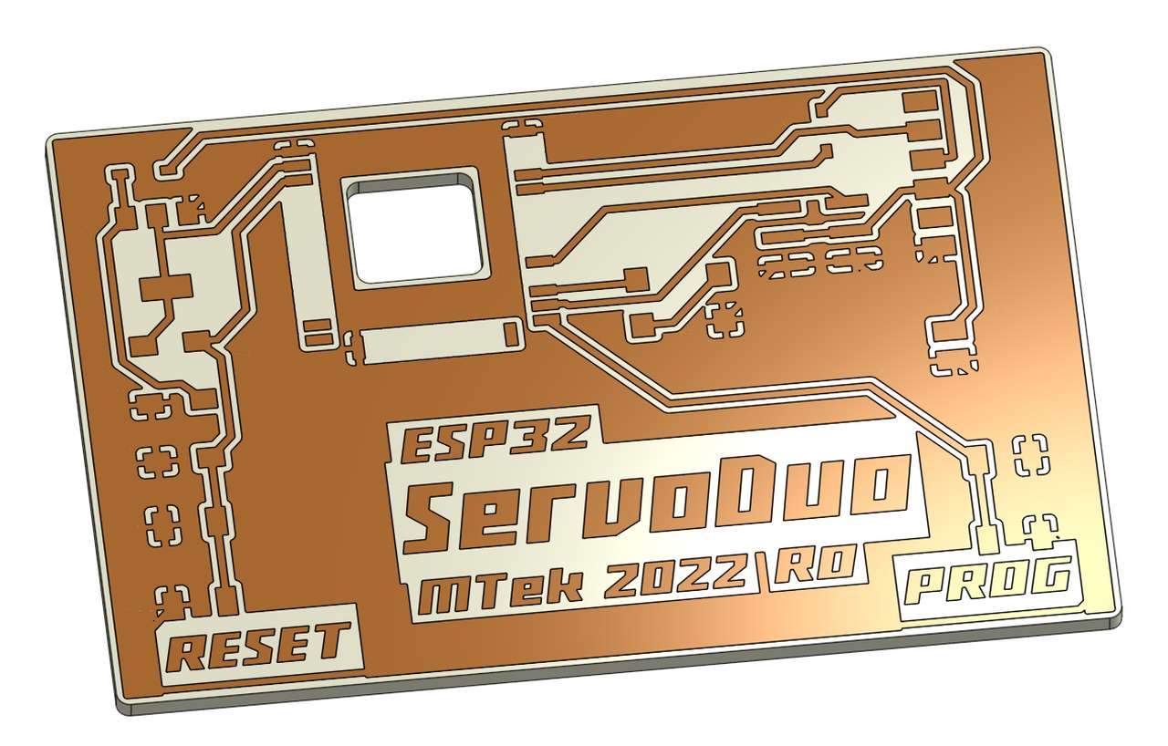 A nice view with components turned off and just the traces on. I’ll use this image to check my milled board against.
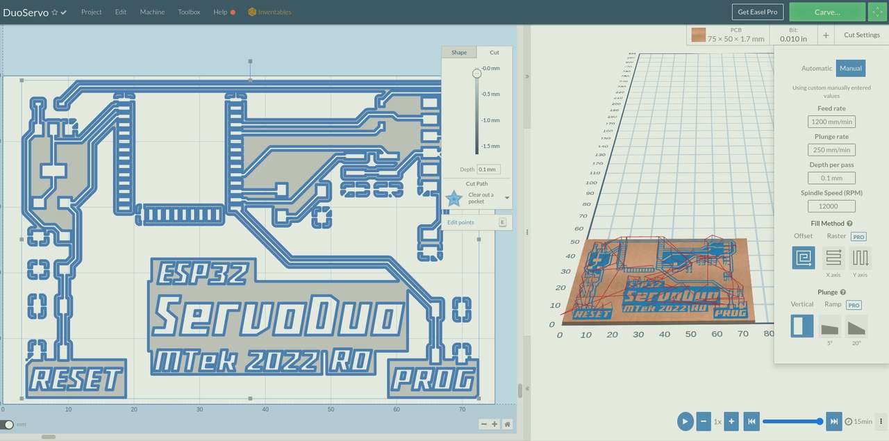
CAM
 CAM toolpaths generated! Time to mill the ServoDuo board!
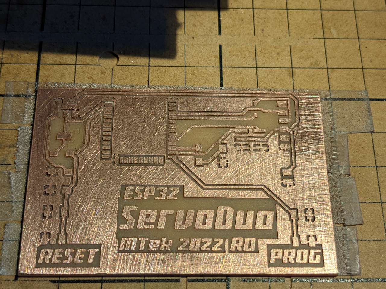
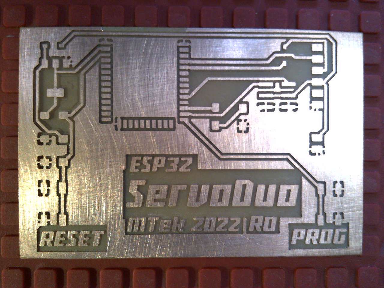
Board Milling
A 0.254mm (0.0100”) diameter 3 flute tapered stub end mill form PreciseBits.
350mm/min feed
25mm/min plunge
0.1mm depth of custom
12,000 rpm
 Tool change to 1.6mm (1/16”) diameter end mill three flute.
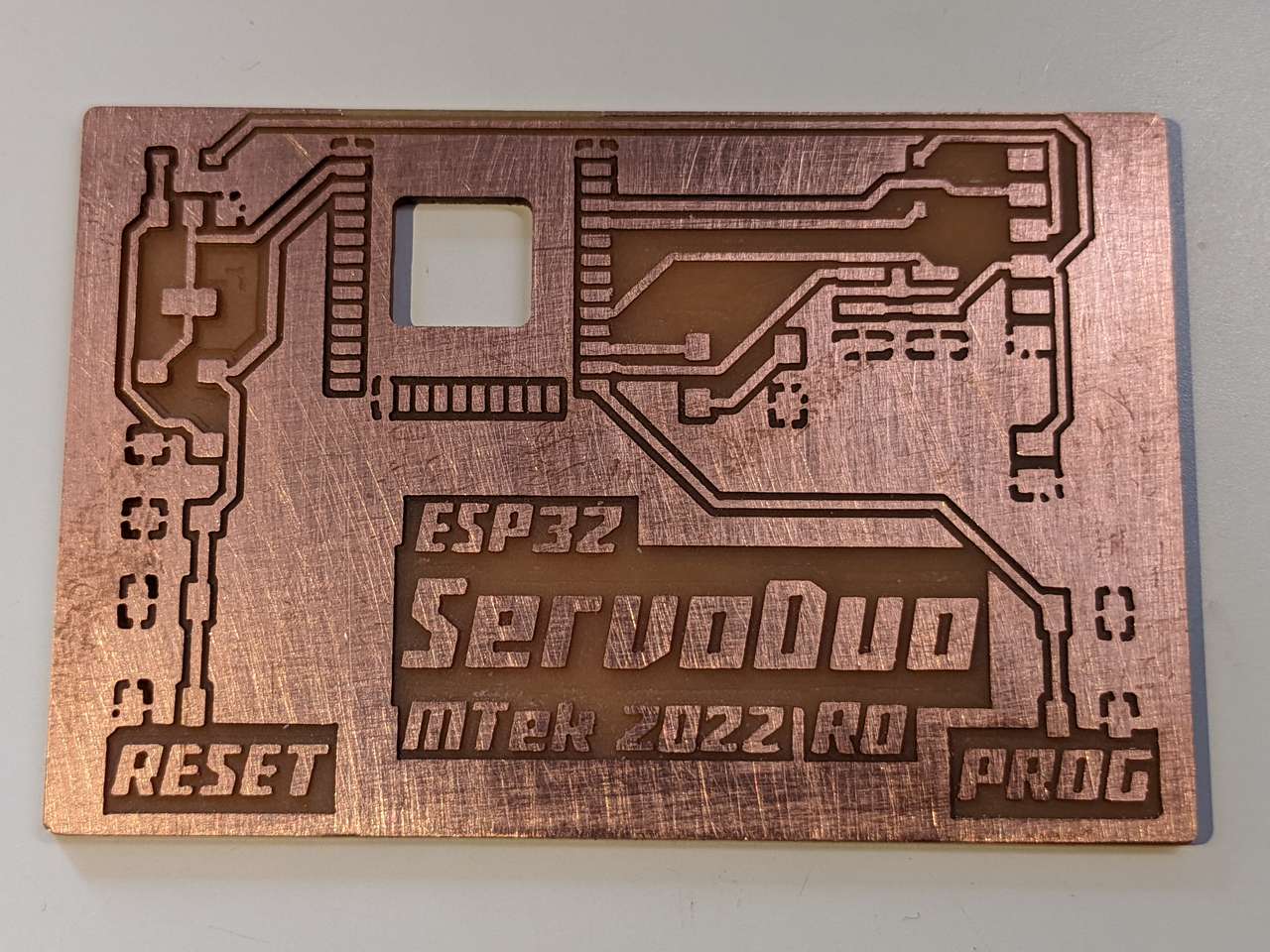 Heatsink pocket and edge milling completed with the 1.6mm diameter end mill.
Interactive HTML BOM
The linked Bill of Materials (BOM) chart was generated directly from KiCAD using the Interactive Html BOM plugin! This BOM format blows my mind and makes picking, placing, and soldering components so much easier and… well Interactive! Installation via the link above was very easy in KiCAD 6.0
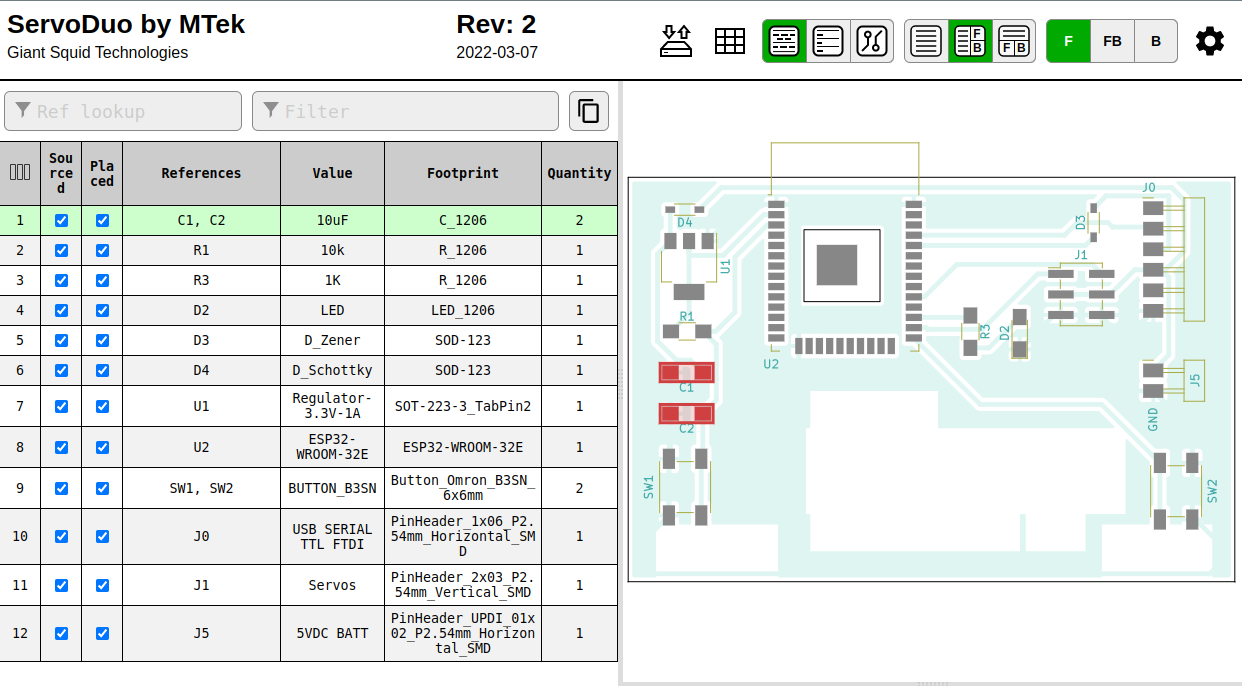 Click on the image above to see the BOM for the ServoDuo board
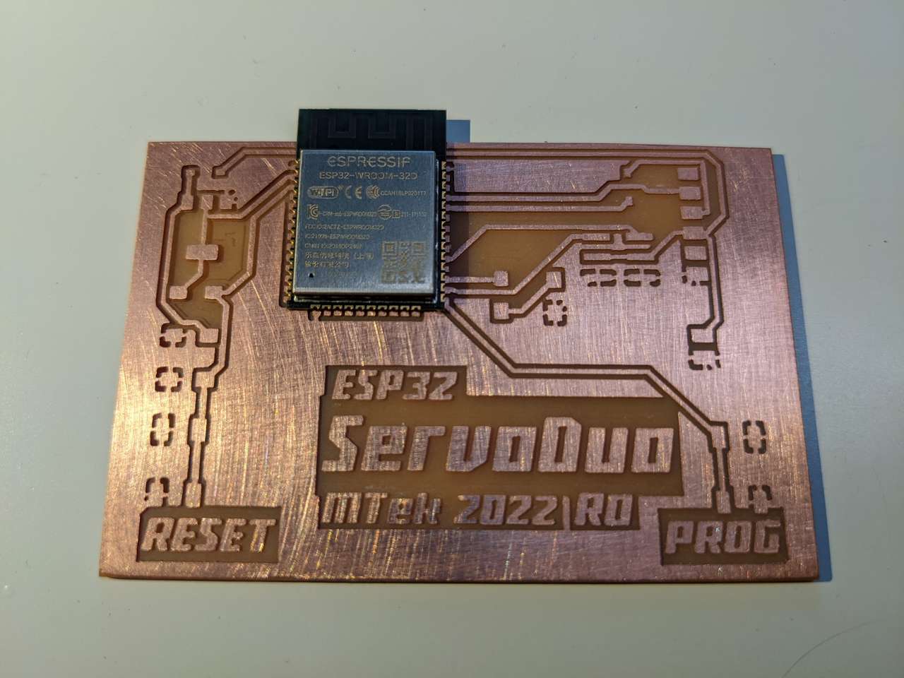
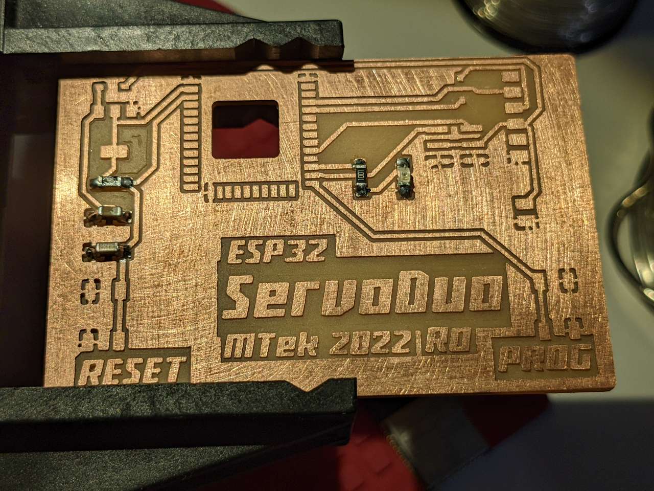
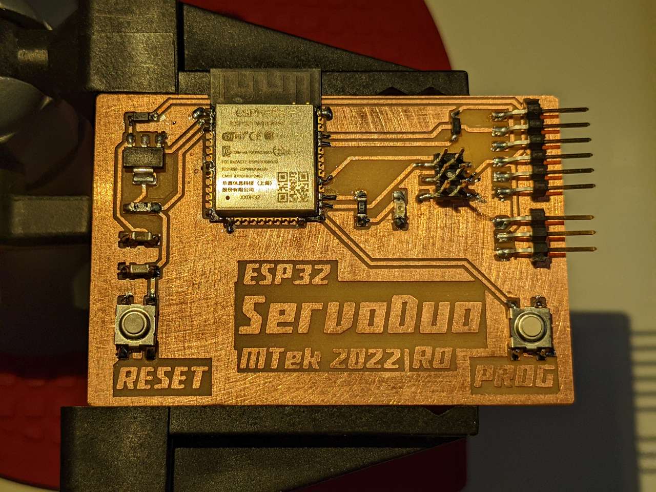
Stuffing
Programming
To make sure my board worked I did a lsusb command to see if I could see the FTDI. I could.
Blink Program
Then I uploaded the following Arduino code to blink the LED on GPIO 16
/*
  Blink

  Turns an LED on for one second, then off for one second, repeatedly.

  ESP32 Flavored edits by Mtek 2022 May 5
  https://fabacademy.org/2020/labs/incitefocus/students/daniel-meyer/assignments/week11/

  modified 8 May 2014
  by Scott Fitzgerald
  modified 2 Sep 2016
  by Arturo Guadalupi
  modified 8 Sep 2016
  by Colby Newman

  This example code is in the public domain.

  http://www.arduino.cc/en/Tutorial/Blink
*/

// the setup function runs once when you press reset or power the board
void setup() {
  // initialize digital pin LED_BUILTIN as an output.
  pinMode(16,OUTPUT);
}

// the loop function runs over and over again forever
void loop() {
  digitalWrite(16,1);   // turn the LED on (HIGH is the voltage level)
  delay(1000);                       // wait for a second
  digitalWrite(16,0);    // turn the LED off by making the voltage LOW
  delay(1000);                       // wait for a second
}
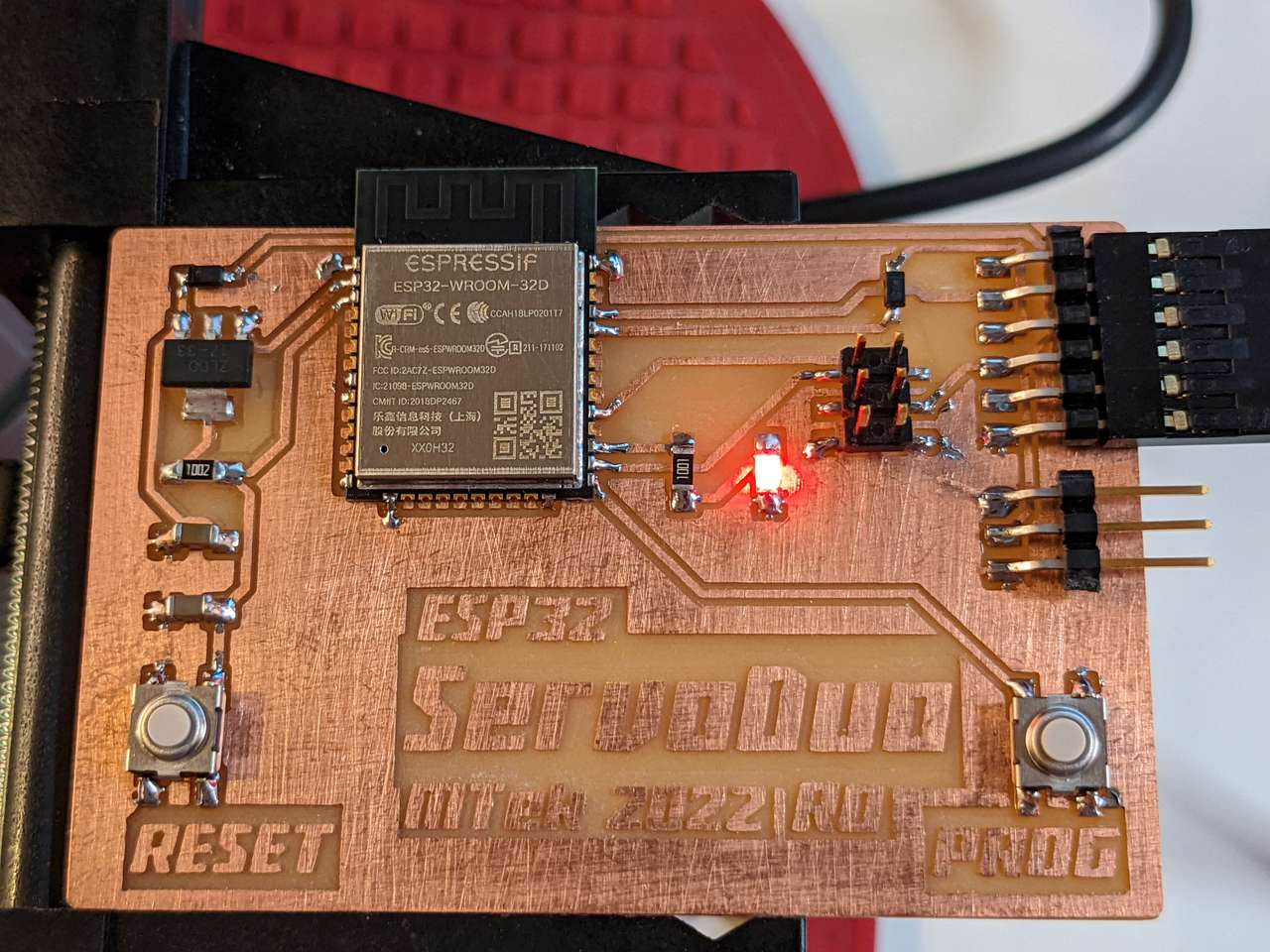
 The test worked the LED turned on for 1 second and off for 1 second!
Servo Sweep Program
Now onto programming a servo sweep.
I uploaded the following Arduino code which I modified to sweep a servo via GPIO 4
/* Sweep
 by BARRAGAN <http://barraganstudio.com>
 This example code is in the public domain.

 modified 8 Nov 2013
 by Scott Fitzgerald

 modified for the ESP32 on March 2017
 by John Bennett

 modified for the ServoDuo Custom Board on May 2022
 by MTek
 See https://fabacademy.org/2020/labs/incitefocus/students/daniel-meyer/assignments/week11/

 see http://www.arduino.cc/en/Tutorial/Sweep for a description of the original code

 * Different servos require different pulse widths to vary servo angle, but the range is
 * an approximately 500-2500 microsecond pulse every 20ms (50Hz). In general, hobbyist servos
 * sweep 180 degrees, so the lowest number in the published range for a particular servo
 * represents an angle of 0 degrees, the middle of the range represents 90 degrees, and the top
 * of the range represents 180 degrees. So for example, if the range is 1000us to 2000us,
 * 1000us would equal an angle of 0, 1500us would equal 90 degrees, and 2000us would equal 1800
 * degrees.
 *
 * Circuit: (using an ESP32 Thing from Sparkfun)
 * Servo motors have three wires: power, ground, and signal. The power wire is typically red,
 * the ground wire is typically black or brown, and the signal wire is typically yellow,
 * orange or white. Since the ESP32 can supply limited current at only 3.3V, and servos draw
 * considerable power, we will connect servo power to the VBat pin of the ESP32 (located
 * near the USB connector). THIS IS ONLY APPROPRIATE FOR SMALL SERVOS.
 *
 * We could also connect servo power to a separate external
 * power source (as long as we connect all of the grounds (ESP32, servo, and external power).
 * In this example, we just connect ESP32 ground to servo ground. The servo signal pins
 * connect to any available GPIO pins on the ESP32 (in this example, we use pin 4.)
 *
 * In this example, a HiTec HS-422 servo is used with power supplied from the 5VDC part of the board.
 * Published Pulse Data: All HiTec servos require 3-5V peak to peak square wave pulse.
 * Pulse duration is from 0.9mS to 2.1mS with 1.5mS as center.
 * The pulse refreshes at 50Hz (20mS).
 * so Servo sweep code with 1000uS to 2000uS leaves a 0.1mS buffer.
 */

#include <ESP32Servo.h>

Servo myservo;
// create servo objects to control servos
// 16 servo objects can be created on the ESP32

int pos = 0;    // variable to store the servo position
// Any ESP32 Pin can be used for PWM but these pins have priority 4,5,16,17,32,33
int servoPin = 4;

void setup() {
  // Allow allocation of all timers
  ESP32PWM::allocateTimer(0);
  ESP32PWM::allocateTimer(1);
  ESP32PWM::allocateTimer(2);
  ESP32PWM::allocateTimer(3);
  myservo.setPeriodHertz(50);    // standard 50 Hz servo
  myservo.attach(servoPin, 500, 2400); // attaches the servo on pin 4 to the servo object
  // using default min/max of 1000us and 2000us
  // different servos may require different min/max settings
  // for an accurate 0 to 180 sweep
}

void loop() {

  for (pos = 0; pos <= 180; pos += 1) { // goes from 0 degrees to 180 degrees
    // in steps of 1 degree
    myservo.write(pos);    // tell servo to go to position in variable 'pos'
    delay(15);             // waits 15ms for the servo to reach the position
  }
  for (pos = 180; pos >= 0; pos -= 1) { // goes from 180 degrees to 0 degrees
    myservo.write(pos);    // tell servo to go to position in variable 'pos'
    delay(15);             // waits 15ms for the servo to reach the position
  }
}
The program above worked well powered by my USB hub and my Sanyo Eneloop NiMH 4.8VDC battery pack.
Multi Servo Series Program
/*
 * ESP32 Servo Example Using Arduino ESP32 Servo Library
 * John K. Bennett
 * March, 2017
 *
 * Source: https://github.com/jkb-git/ESP32Servo/blob/master/examples/Multiple-Servo-Example-Arduino/Multiple-Servo-Example-Arduino.ino
 *
 * Modified by MTek 2022 May 8 for two servos using a custom milled board
 *
 * https://fabacademy.org/2020/labs/incitefocus/students/daniel-meyer/assignments/week11/
 *
 * This sketch uses the Arduino ESP32 Servo Library to sweep 2 servos in sequence.
 *
 * Different servos require different pulse widths to vary servo angle, but the range is
 * an approximately 500-2500 microsecond pulse every 20ms (50Hz). In general, hobbyist servos
 * sweep 180 degrees, so the lowest number in the published range for a particular servo
 * represents an angle of 0 degrees, the middle of the range represents 90 degrees, and the top
 * of the range represents 180 degrees. So for example, if the range is 1000us to 2000us,
 * 1000us would equal an angle of 0, 1500us would equal 90 degrees, and 2000us would equal 1800
 * degrees.
 *
 */

#include <ESP32Servo.h>

// create four servo objects
Servo servo1;
Servo servo2;

// Published values for SG90 servos; adjust if needed
int minUs = 500;
int maxUs = 2400;

// These are all GPIO pins on the ESP32
int servo1Pin = 4;
int servo2Pin = 5;

int pos = 0;      // position in degrees

void setup()
{
  servo1.attach(servo1Pin, minUs, maxUs);
  servo2.attach(servo2Pin, minUs, maxUs);
}

void loop() {
  for (pos = 0; pos <= 180; pos += 1) { // sweep from 0 degrees to 180 degrees
    // in steps of 1 degree
    servo1.write(pos);
    delay(20);                       // waits 20ms for the servo to reach the position
  }
  for (pos = 180; pos >= 0; pos -= 1) { // sweep from 180 degrees to 0 degrees
    servo1.write(pos);
    delay(20);
  }

  for (pos = 0; pos <= 180; pos += 1) { // sweep from 0 degrees to 180 degrees
    // in steps of 1 degree
    servo2.write(pos);
    delay(20);                       // waits 20ms for the servo to reach the position
  }
  for (pos = 180; pos >= 0; pos -= 1) { // sweep from 180 degrees to 0 degrees
    servo2.write(pos);
    delay(20);
  }
}
Powered by my USB Hub, the program above drove the HiTec HS-422 Analog Servo well. However while driving the Corona DS-239MG Digital Servo the servo stopped and emitted a buzzing sound, indicating a current induced brownout. I have several decades of experiences seeing servo brownouts. So I tried driving the two servos with my Sanyo Eneloop NiMH 4.8VDC battery pack, and everything worked perfectly and at full power!
Hero Shots
CAD/EDA Files
SVG for Board Milling (.svg 90.1 kB)
KiCAD Project(.kicad_pro 9.3 kB)
KiCAD Schematic(.kicad_sch 88.8 kB)
KiCAD PCB(.kicad_pcb 195.8 kB)
Onshape 3D CAD of complete board and components (direct cloud link)
References
Using Servo Motors with ESP32 Multiple-Servo-Example-Arduino
Archive
This section contains projects that were spiraling too wide and I decided to required too much time to complete this assignment. But since I document as I go I will keep this info so I can complete these fun projects after graduation!
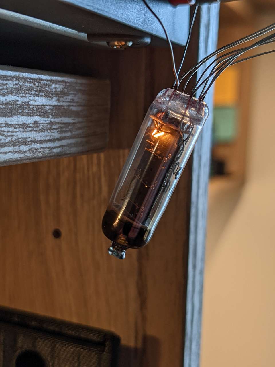
ИВ-9 (IV-9) Numitron Tube
I decided this project was too complicated and will save if for the future. I have four ИВ-9 Numitron Tubes that I picked up years ago from somewhere… American Science and Surplus here in Chicago may have been where I got them. Anyway, I thought maybe they would be good candidates for an output. Now to find specs on these weird little guys.
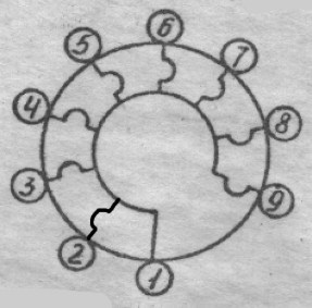
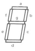
Apparently Numitron Tubes are filament based number display tubes that run at ~5VDC. Seven filament segments are for making numbers and one set of smaller filaments as a decimal point. (Sources 1.) The numbers created are 10mm tall. The tube measures 11mm ⌀ x 35mm H.
Specifications
| Pin | Segment |
|---|---|
| 1 | gnd |
| 2 | dec |
| 3 | b |
| 4 | c |
| 5 | a |
| 6 | f |
| 7 | g |
| 8 | d |
| 9 | e |
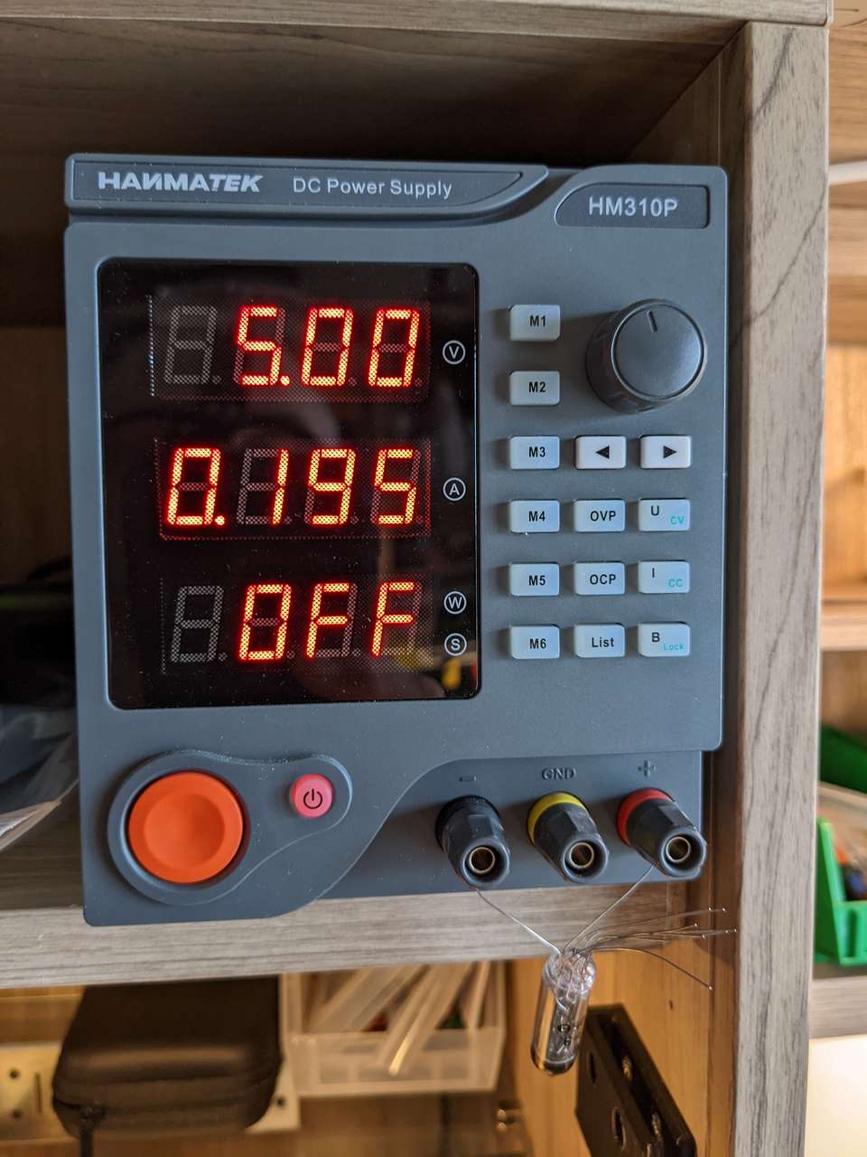
Current per segment: 19.5 mA 19.5mA x 8 segments = 156 mA Voltage: 4.5V Pin ⌀: 0.5mm
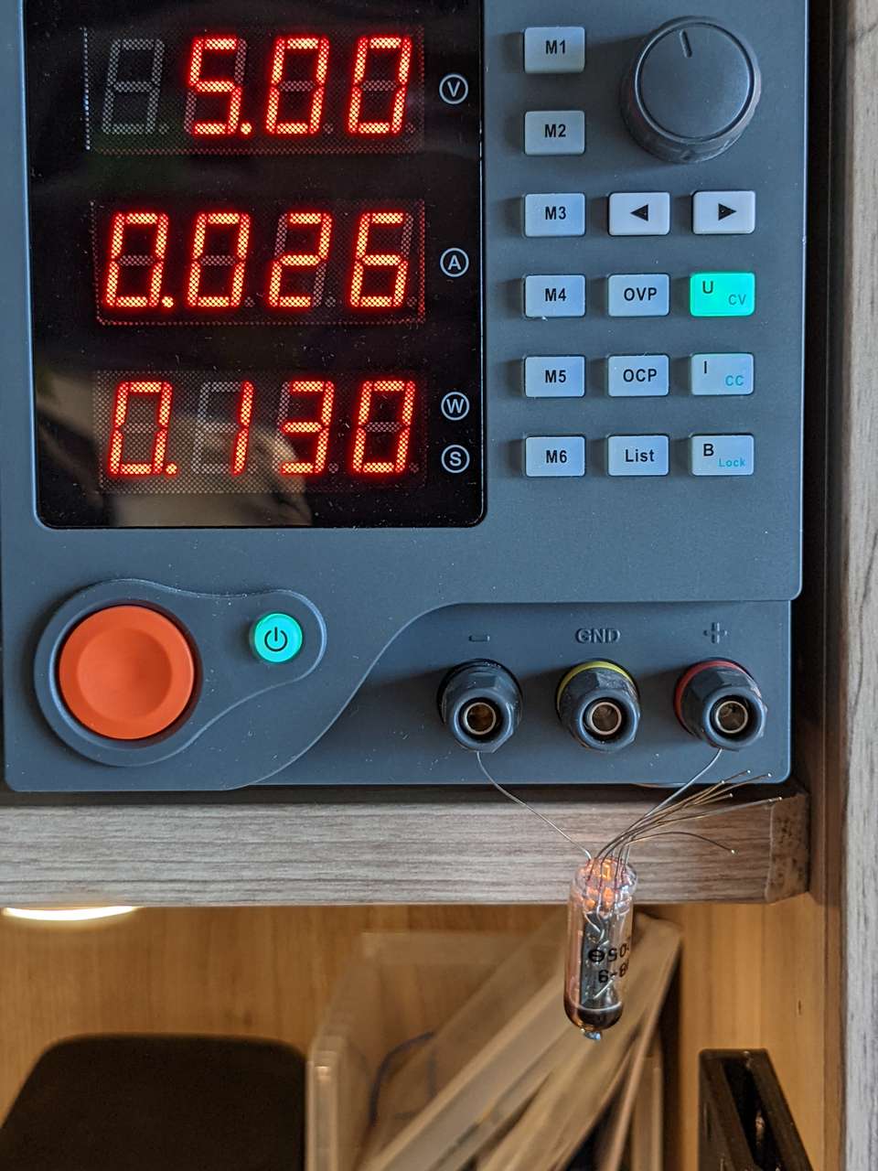
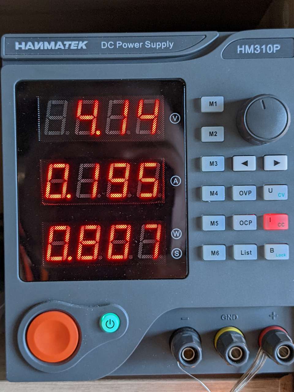
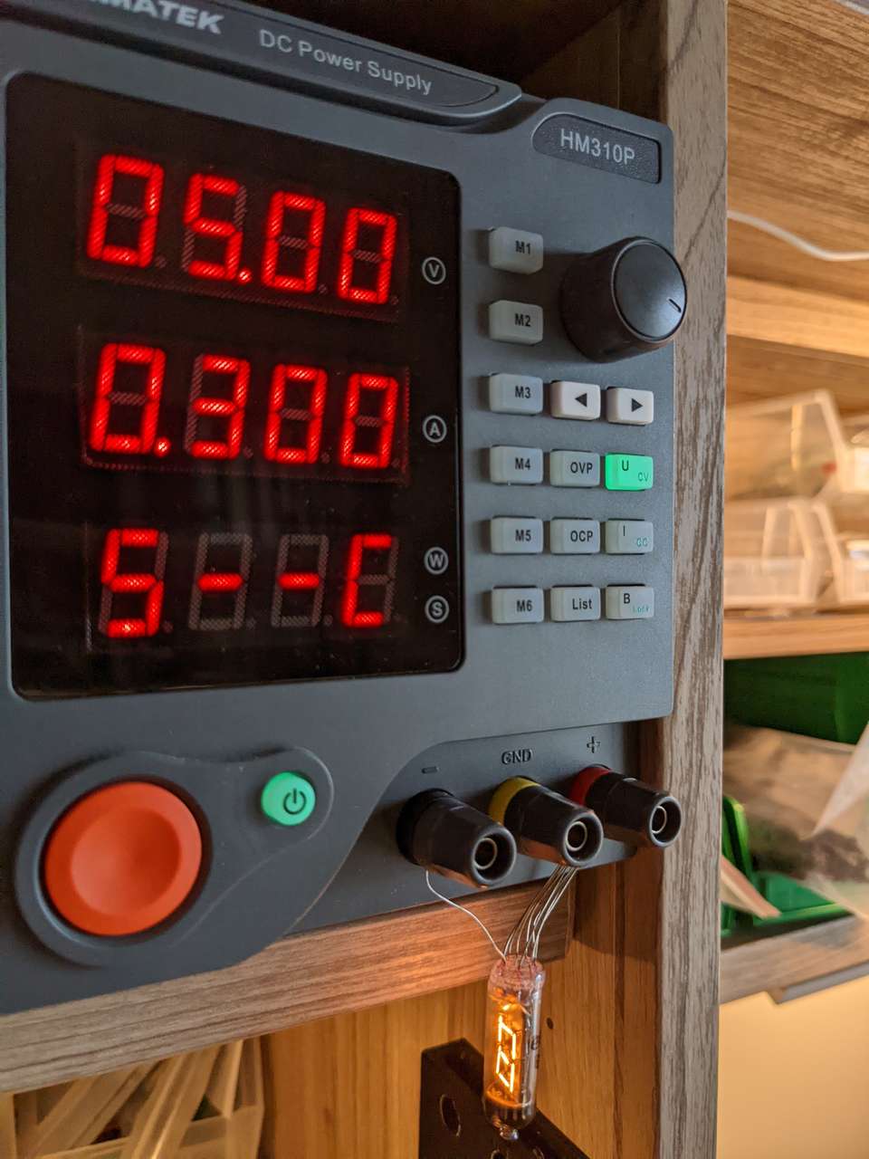
Measure Power
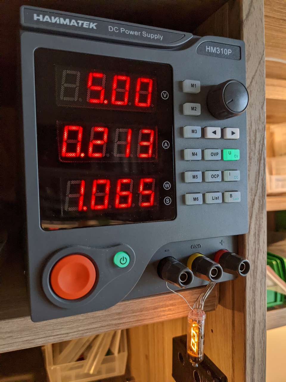
I hooked the Numitron to my lab power supply, setting it to 5.00V at 195mA. I did this for the first on the decimal and it lit up nicely.
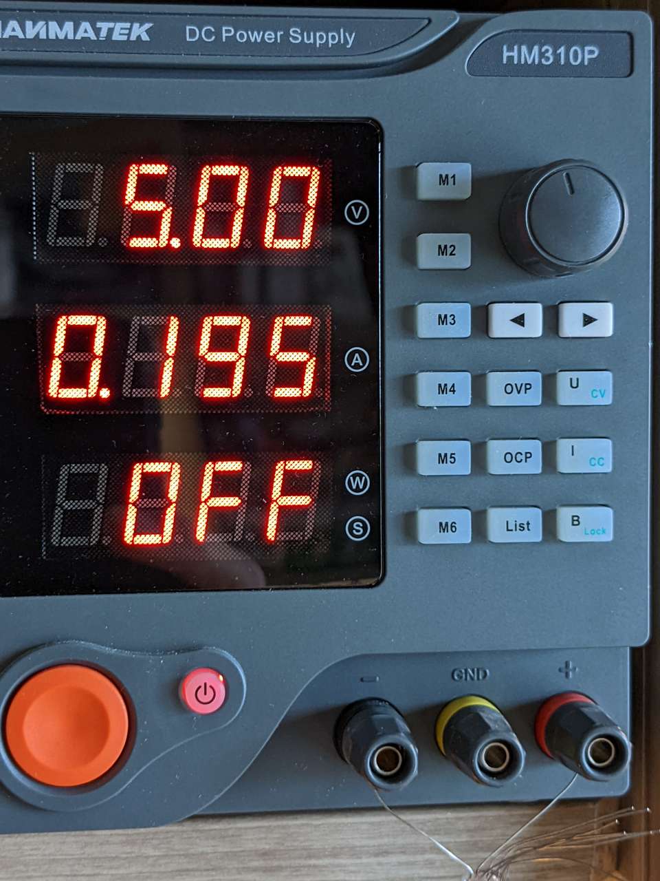
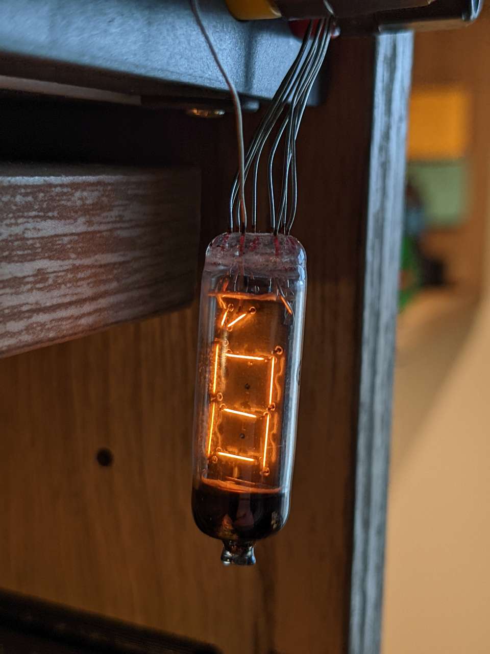
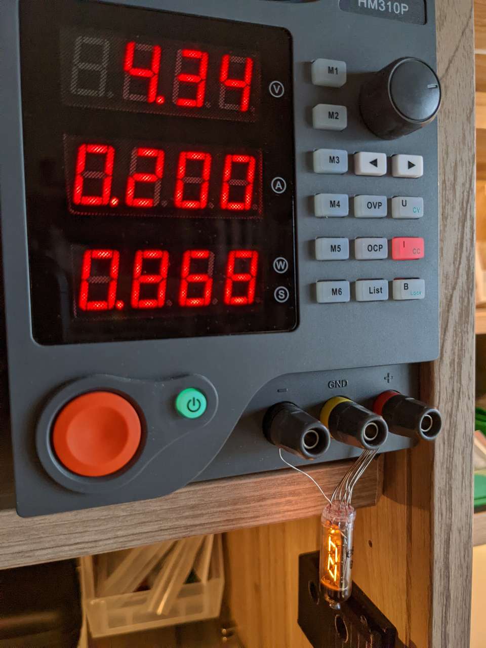
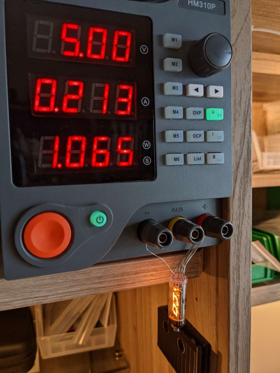
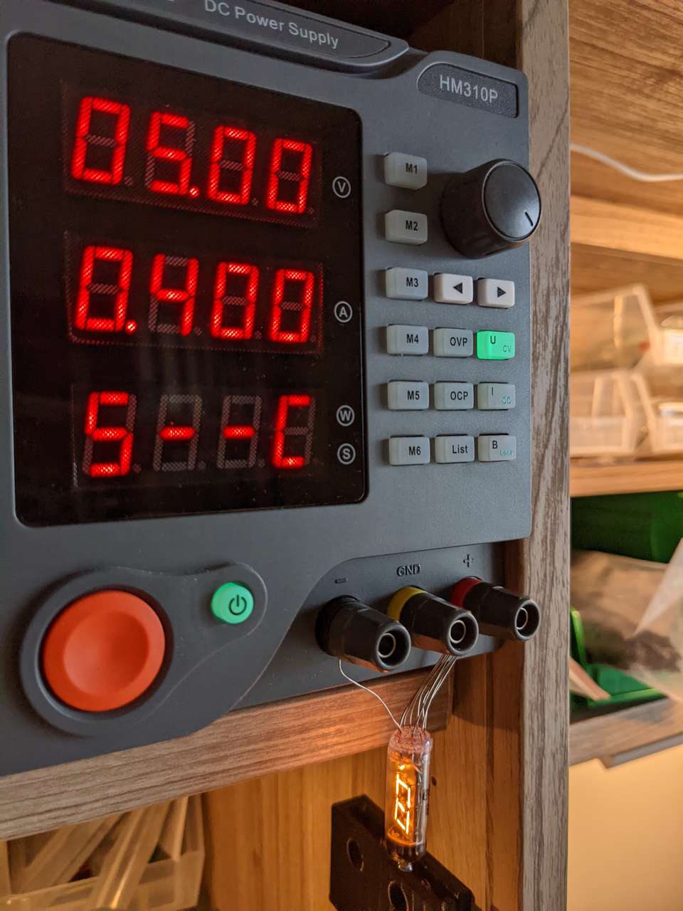
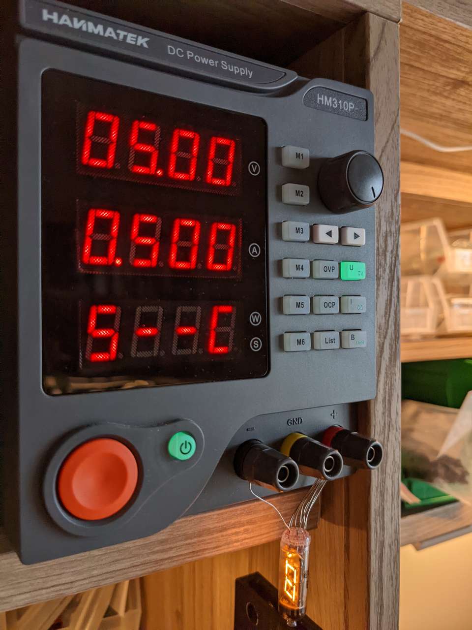
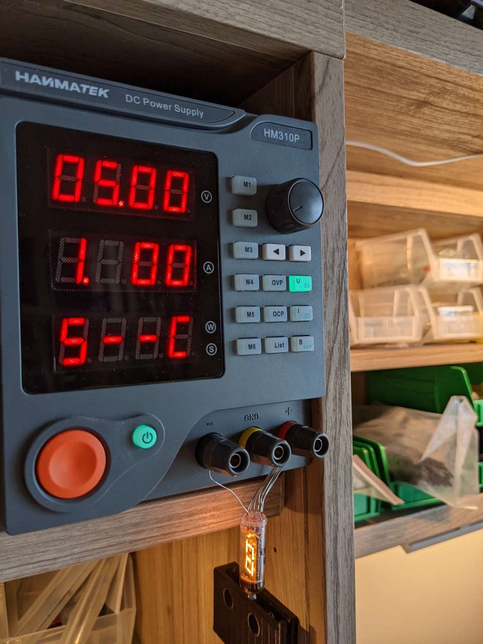
Then I hooked up all segments at 195mA, and well all the numbers lit up at about the same brightness. Hmmm are the specs correct this certainly seems like the specs might be off I think the spec is 19.5mA per tube not per segment. Let’s increase power a bit. .200A a tiny bit brighter, then .300A only 213mA.
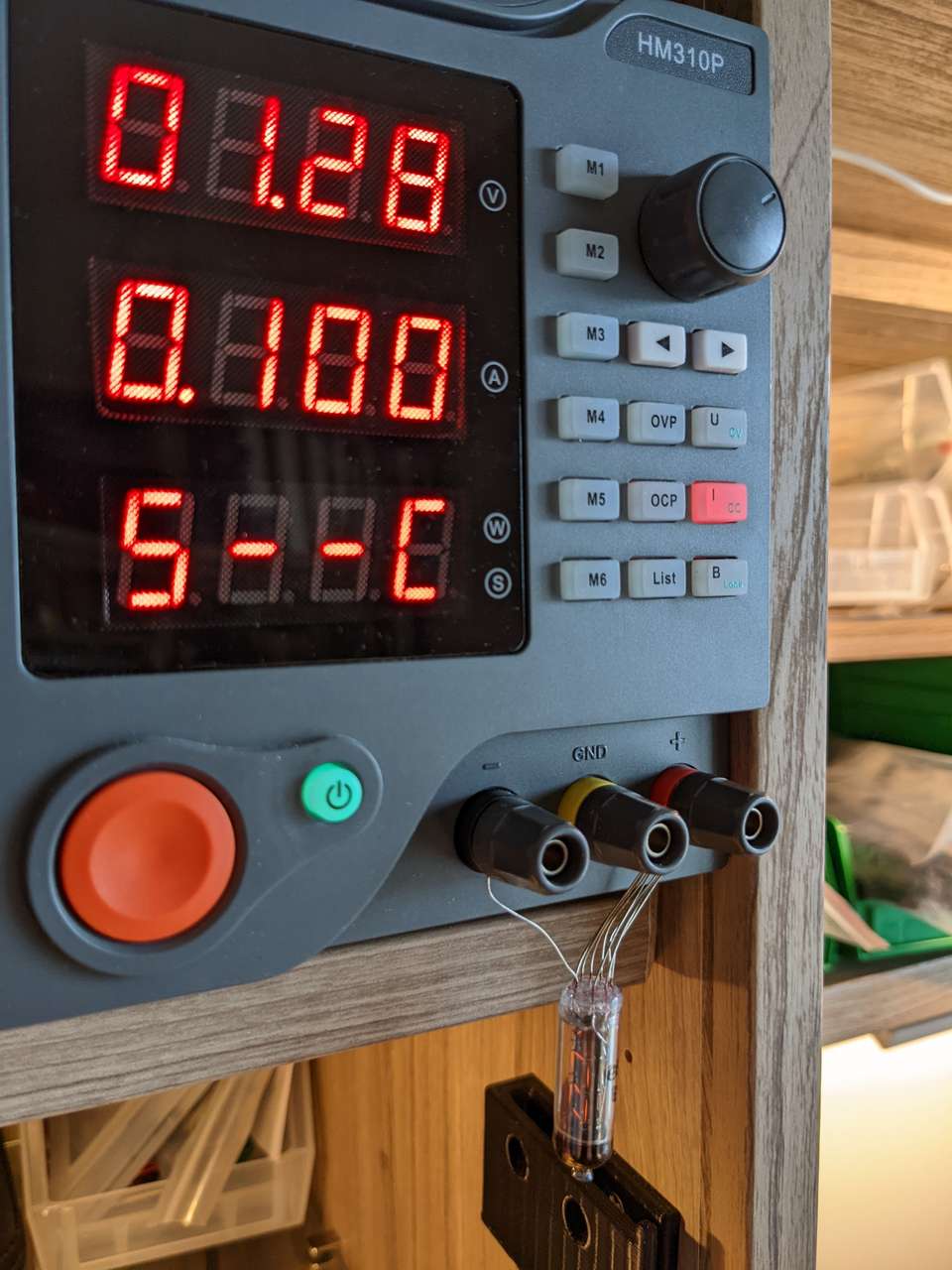
Ok lets try 4.5V and max draw is 200ma.
A lot of folks on the internet interpret the current per segment rating as 19.5mA and that means it must have limited current or burn out similar to an LED. This seems a bit weird to me. These Numitron tubes were made in the USSR for use in what I would guess would be military or industrial devices. I very much doubt there were current limiting resistors used in these types of applications. I think they were driven with close to 4.5 volts and the typical segment draw would be 19.5 mA per segment, just so the engineers new how much power draw there was per segment. I think that brightness / dimming would be simply controlled by voltage increase and decrease probably with a rotary pot labeled dimmer.
I was thinking I could possible simplify the circuit by quite a bit if I drove one Numitron tube at 3.3VDC directly off the output pins of the ESP32 let’s check to see what kind of current can be driven off 3.3V on and ESP32. I found this discussion of the ESP32 datasheet Current Limits. This discussion says that the I/O’s can SOURCE 20 to 40mA and SINK up to 28mA on STRENGTH 3 The sum of all the I/O current may not exceed 1200mA. I’m going to take a gamble and assume that my 3.3v regulator with a 1 amp max output can source the required power to the I/O’s and that 28mA per segment is plenty of power.
To test my theory before design and milling an entire board I will use a my ESP32 dev module connected to a breakout board.
Being a filament bulb, I also wonder if I could simply supply 3.3V to common wire and sink outputs to ground? All I/O’s can handle sinking at 28mA on STRENGTH 3
Constant Current and Constant Voltage
Note the green and red buttons in the photos below. Red is Constant Current set with Voltage free, Green is Constant Voltage with current free. I experimented with voltage and current settings set as close to the spec sheet as possible to see if there were any issues dimming the Numitron and also to see the impact on brightness. I suspect a dimmer Numitoron would last longer. It would be cool to add an auto dimming feature to the clock I build with a light sensor. I would love to look at the time in the middle of night on my Numitorn clock with the filaments barely glowing.

MTek Numitron Counter
I will build a Numitron Clock or counter in the future. Maybe I will add auto dimming. A ESP32 or WiFi capable microcontroller would be wicked and counter the analog nature of the Numitron tubes. A nice wood and glass case, sealed against dust, would be awesome. The case would be milled on a low cost CNC mill with rounded corners, from rare wood (sourced via Brain Di’Agnstic of the Wood Shop Art Galley). I would oil the wood as recommended by Brian. Brian and I would laser engrave a logo and serial number on the clock, using his low cost Fabool laser. Maybe we would consider selling a limited number of the MTek Numitron Clock at the Wood Shop Art Galley