7. Electronics design
Assignment
| Have you? | Done |
|---|---|
| Group assignment: | ⬇ |
| Use the test equipment in your lab to observe the operation of a microcontroller circuit board | |
| check operating voltage | Yes |
| use oscilloscope to check noise of operating voltage | Yes |
| use oscilloscope to interpret a data signal | Yes |
| document your work (in a group or individually) | Yes |
| Individual assignment: | ⬇ |
| Redraw one of the echo hello-world boards or something equivalent | Yes |
| add a button and LED (with current-limiting resistor) | Yes |
| check the design rules | Yes |
| make it | Yes |
| test it. | Yes |
Checklist
| Have you? | Done |
|---|---|
| Link to the group assignment page | Yes |
| Documented what you have learned in electronics design | Yes |
| Explained problems and how you fixed them | Yes |
| Included original design files (KiCad) | Yes |
| Included a ‘hero shot’ of your board | Yes |
| Loaded a program and tested if your board works | Yes |
Need to complete
- Use oscilloscope to interpret a data signal
- Document results on group page
FAQ
Can I modify an existing design board? Answer: No, you have to create your board from scratch.
Do I need to create a schematic file? Answer: Yes, at least for this week.
Can I draw my design by hand? Answer: Yes, but you have to use EDA software for this week.
EDA Software
After some experiments with EagleCAD I decided to try KiCad. It’s open source and runs on Linux locally. I found these two guides useful: 1. Introduction to KiCad I started the official Kicad tutorial and it’s pretty easy to follow! 2. 2019 BCN KiCad tutorial. The FAB library can be imported, so that is quite powerful. BCN: Kicad Electronics design
KiCad on Linux
In 2022 I needed to update KiCad to ver 6.x from 5.x and update the FAB Libraries to the latest version. I used these guides to do so: 1. Fab electronics component library for KiCad 2. Install KiCad on Linux Mint
For my own future reference my KiCad Fab libraries are located at /home/meistertek/Documents/Fab Academy/KiCad Libraries/2022 Fab Library
ESP32 Boards
I need to learn electronic design for the ESP32 microcontroller module, I will use a ESP32 in my final project.
I decided to stick with only ESP32 microcontrollers in 2022. So for this assignment I will take a ESP32 Hello world board and redraw it in KiCad and add a button or capacitive copper strip to fade a LED or proportionally control a servo.
For 2022 I will redo this assignment by re-drawing an ESP32 hello world board.
I will then add programmable button and led. This will address the mistake I made in 2020 when I added a non-programmable switch and led.
ESP32 Datasheets
Base ESP32 chips in below modules ESP32WROOM32D & ESP32WROOM32U ESP32WROOM32E/UE ESP32S2WROVER/-I
ESP32 Pinout Diagram
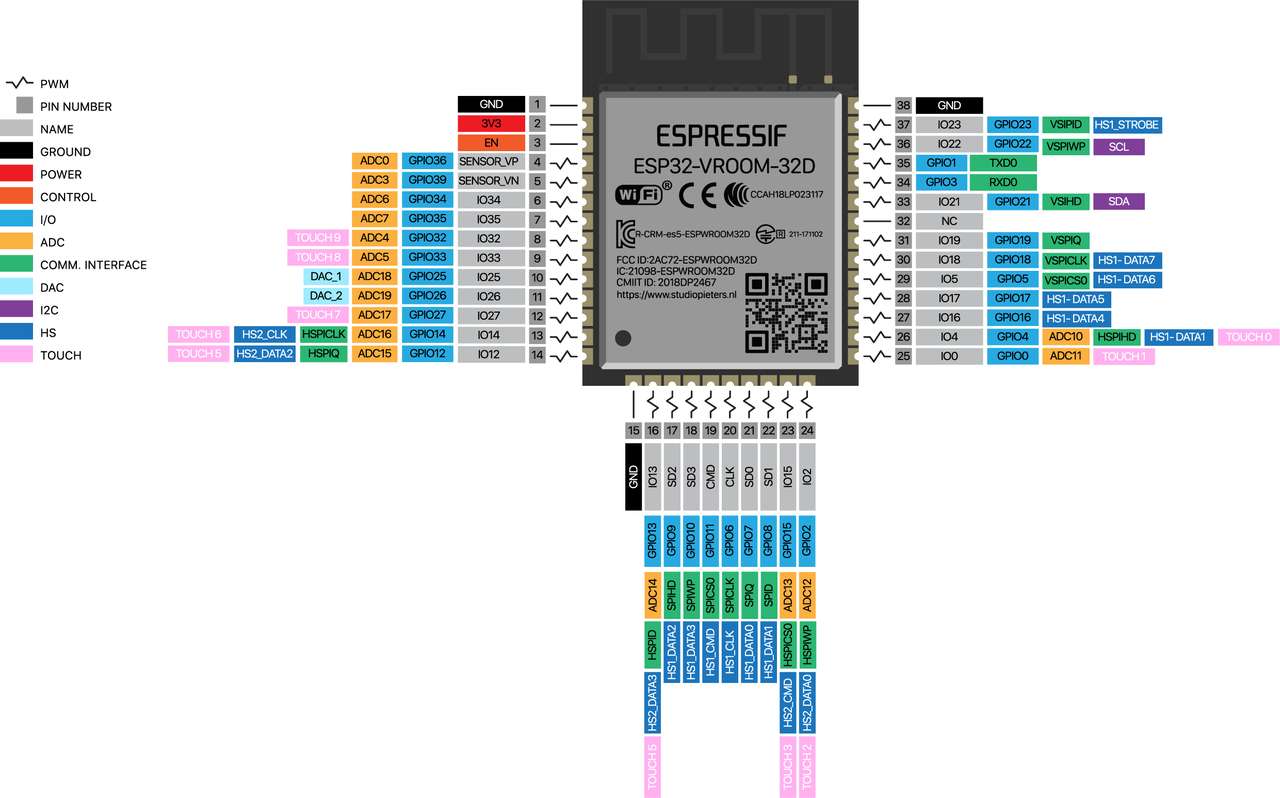
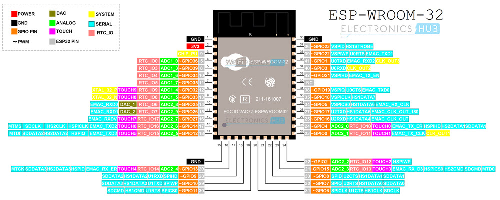
ESP32 101
Programming Adafruit HUZZAH32 – ESP32 Feather Board Plan
I decided to program a ESP 32 Dev board from Adafruit before tackling my custom ESP 32 boards. This would allow me to focus on building up my programming skills on without distractions of board milling and trouble shooting. I purchased this board Adafruit HUZZAH32 – ESP32 Feather Board
Assembled Terminal Block Breakout FeatherWing for all Feathers Breakout board I used with above to ease connecting to input and output devices. Adafruit learn guide for the HUZZAH32 How to install the Espressif Arduino support
Belt Grids
At our Fab Lab we have developed a system based on karate belt colors to scaffold learning of a specific technology or project.
Since I am new to programming microcontrollers I needed to scaffold my learning a bit. So I made a project grid belt board column to plan this assignment:
ESP32 101 Belt Grid
| Belt | Activity | Done |
|---|---|---|
| WHT | Read Learn:Adafruit HUZZAH32 ESP32 Feather | Yes |
| YEL | Linux Arduino IDE 1 Installation | Yes |
| ORG | Install expressif Arduino core for the ESP32 | Yes |
| GRN | Connect HUZZAH32 board, query w lsusb command record results | Yes |
| BLU | Load Arduino IDE Blink Sketch, verify blinks LED | Yes |
| PUR | Add code to above for button to toggle the LED on and off | Yes |
| RED | Connect servo, sweep with servo sweep sketch | Yes |
| BRN | Add servo and sweep, trigger sweep with button | Yes |
| BLK | Add RC stick pots, move servo proportionally | Skip |
Powering HUZZAH32
I was wondering if it would be safe to power the Huzzah32 and ESP32 Chips with four AA NiMH batteries. The USB specification states that the 5v is supposed to be +-5% under load, this is 4.75v to 5.25v. Four AA NiMH batteries fully charged are 1.45V, and quickly drops to 1.3V once used. This means the a freshly charged 4 AA pack will run at 5.8V (1.45Vx4), quickly drops to 5V (1.25Vx4). At 4.6V (1.15Vx4) NiMH batteries experience a steep drop off in voltage indicating full discharge. Reference: What is the recommended fully-charged voltage for NiMH AA batteries?
This means my four AA NiMH pack will start at 5.8V and stop at 4.6V this is very close to the USB voltage spec of 5.25v to 4.75v. To me this seems close enough to not require a voltage regulator. I’ll see what happens in actual practice!
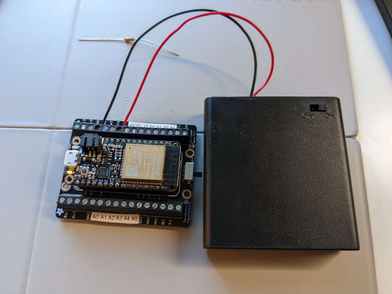 Huzzah32 under 5vdc power with 4AA NiMH battery Pack.
I must remember that if I use a raw ESP32 chip not in a dev-board or module, a 3.3V regulator will be needed. The 5V battery pack will need to be wired onto a separate bus for connecting 5V servos and motors.
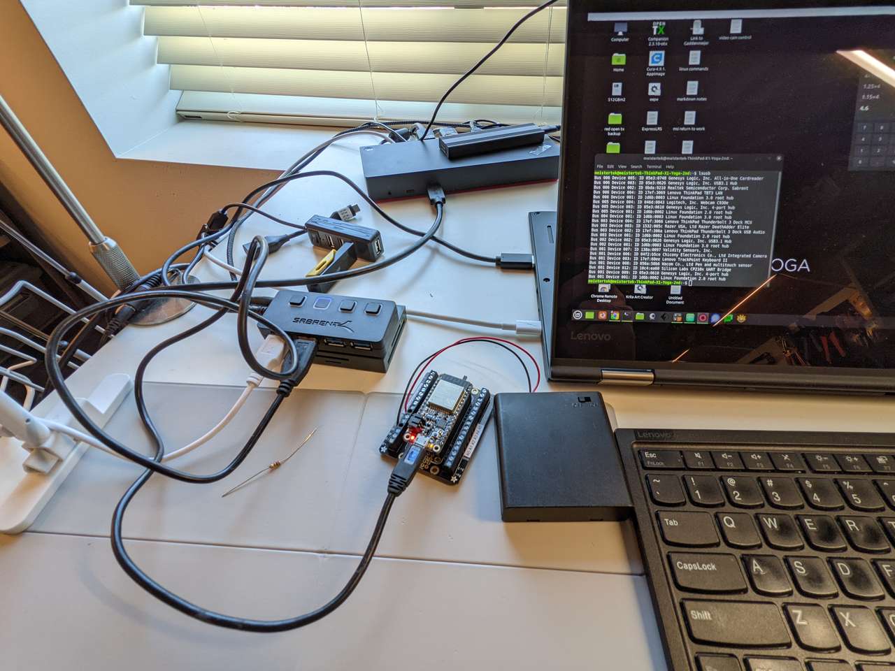
lsub command
After plugging in the HUZZAH32 to USB I ran the lsusb command and the board showed up as:
Bus 001 Device 014: ID 10c4:ea60 Silicon Labs CP210x UART Bridge
The CP2104 chip is used on the huzzah for USB communication.
Arduino IDE sketchs
Arduino IDE blink sketch
In the Arduino IDE software I loaded up the The blink sketch by selecting File, Examples, Basics, Blink.
Next I selected Tools, Board: ESP32 Arduino, Adafruit ESP32 Feather. I left the defaults in the other slots of Tools.
Then clicked Upload. The LED Blinked 1 second on 1 second off. I changed the code to keep the LED on for two seconds and off for .5 seconds. I clicked Upload and the LED did as commanded.
This code uses LED_BUILTIN which will set the LED output to pin 10 which is GPIO #13
/*
  Blink

  Turns an LED on for one second, then off for one second, repeatedly.

  Most Arduinos have an on-board LED you can control. On the UNO, MEGA and ZERO
  it is attached to digital pin 13, on MKR1000 on pin 6. LED_BUILTIN is set to
  the correct LED pin independent of which board is used.
  If you want to know what pin the on-board LED is connected to on your Arduino
  model, check the Technical Specs of your board at:
  https://www.arduino.cc/en/Main/Products

  modified 8 May 2014
  by Scott Fitzgerald
  modified 2 Sep 2016
  by Arturo Guadalupi
  modified 8 Sep 2016
  by Colby Newman

  This example code is in the public domain.

  http://www.arduino.cc/en/Tutorial/Blink
*/

// the setup function runs once when you press reset or power the board
void setup() {
  // initialize digital pin LED_BUILTIN as an output.
  pinMode(LED_BUILTIN, OUTPUT);
}

// the loop function runs over and over again forever
void loop() {
  digitalWrite(LED_BUILTIN, HIGH);   // turn the LED on (HIGH is the voltage level)
  delay(1000);                       // wait for a second
  digitalWrite(LED_BUILTIN, LOW);    // turn the LED off by making the voltage LOW
  delay(1000);                       // wait for a second
}
 Here is LED 13 in it’s on state, it’s LED to the left of the USB port.
Button toggles LED
I used this guide to help me add code to turn the led on and off
I used 21 - General purpose IO pin #21 for my button. I looked back at the ESP32 Feather,Pinouts page often to make sure that my code would work with the pinouts assigned.
I followed the ESP32-Button-Debounce tutorial at ESP32 I/O to learn how to use code to make the button work properly, including debounce.
Next I moved on to the ESP32-button-toggle-led tutorial. I used the code that calls the ezButton.h library. I had to change the code to work with my HUZZAH32 board. I used PIN 21 for my button and PIN 13 with the built in red LED.
This didn’t work since I didn’t have the ezButton.h library installed. So I went to Tools, Manage Libraries, in the Arduino IDE, searched for ezButton, and installed it. Details on the ezButton library.
I uploaded my code to the HUZZAH32, and despite warnings of being for a different microcontroller, it worked! I could toggle the LED on and off with a button press! Cool!
Note: LED on right is lipo battery charging light. LED on left is programmable LED in GPIO13.
Button servo sweep
This was the moment I was looking forward to, sweeping a servo. I used this ESP32-Servo Motor tutorial to help me. I used the pin 27 GPIO #27 on the HUZZAH32 for the servo. I also had to stack the red +5VDC wire of my battery pack on the USB terminal, and the GND wire of my servo to the same GND as my battery pack. I know from experience that hobby servos can draw a lot of current and giving them a direct connection to a battery helps make sure adequate current is supplied. I was also ready for brownouts to occur if powered from a USB port. Some USB ports do not provide enough current to drive a servo. To be safe I used a female servo connector, so I could upload my code and then disconnect from USB power and then run off my high current capable Sanyo Eneloop NiMH battery pack.
I uploaded the code and got this error
Multiple libraries were found for "Servo.h"
 Used: /home/meistertek/Arduino/libraries/Servo Not used: /home/meistertek/Documents/Apps/Arduino/arduino-1.8.13/libraries/Servo
I went to Tools, Manage Libraries in the Arduino IDE, searched for servo, well holy shit, there are a lot of cool libraries for servos in there, including many for ESP32 boards. I spent a little time clicking on the More info links to learn more about the different servo libraries. Some of these servo libraries I will revisit later for my RC aircraft hobby. I eventually came to the great guide Using Servo Motors with ESP32 by the DroneBot Workshop and they suggested using the ESP32Servo Library by Kevin Harrington. I installed the ESP32Servo Ver 0.11.0 library.
Next I used the code Example 1 - Sweep. I also visited the Hitec servo site to make sure I had the right code variables to use with my Hitec HS-422 servo: Hitec General Servo Manual. The line that I needed said:
Pulse Data. All Hitec servos require 3-5V peak to peak square wave pulse. Pulse duration is from 0.9mS to 2.1mS with 1.5mS as center. The pulse refreshes at 50Hz (20mS).
I know from most RC applications that 0.1mS buffer is used, so the Servo sweep code with 1000uS to 2000uS leaves this 0.1mS buffer. The code variables were correct for my servo.
Next I uploaded my code to the HUZZAH32. The code compiled and uploaded without errors. But something was wrong, my servo didn’t move and the red LED was dimly lit. I realized that I hadn’t switched to the pins I needed to run my servo. Instead the PWM servo signal was powering my LED on pin 13 instead of my servo on pin 27. I edited the code to int servoPin = 27;
I re-uploaded my code… and it worked!
/* Button Sweep
 by BARRAGAN <http://barraganstudio.com>
 This example code is in the public domain.

 modified 8 Nov 2013
 by Scott Fitzgerald

 modified for the ESP32 on March 2017
 by John Bennett

 modified on Feb 2022 for button triggering on a ESP32
 by Dan "MTek" Meyer

 see http://www.arduino.cc/en/Tutorial/Sweep for a description of the original code

 * Different servos require different pulse widths to vary servo angle, but the range is
 * an approximately 500-2500 microsecond pulse every 20ms (50Hz). In general, hobbyist servos
 * sweep 180 degrees, so the lowest number in the published range for a particular servo
 * represents an angle of 0 degrees, the middle of the range represents 90 degrees, and the top
 * of the range represents 180 degrees. So for example, if the range is 1000us to 2000us,
 * 1000us would equal an angle of 0, 1500us would equal 90 degrees, and 2000us would equal 180
 * degrees.
 *
 * Circuit: (using an ESP32 Thing from Sparkfun)
 * Servo motors have three wires: power, ground, and signal. The power wire is typically red,
 * the ground wire is typically black or brown, and the signal wire is typically yellow,
 * orange or white. Since the ESP32 can supply limited current at only 3.3V, and servos draw
 * considerable power, we will connect servo power to the VBat pin of the ESP32 (located
 * near the USB connector). THIS IS ONLY APPROPRIATE FOR SMALL SERVOS.
 *
 * We could also connect servo power to a separate external
 * power source (as long as we connect all of the grounds (ESP32, servo, and external power).
 * In this example, we just connect ESP32 ground to servo ground. The servo signal pins
 * connect to any available GPIO pins on the ESP32 (in this example, we use pin 18.
 *
 * In this example, we assume a Tower Pro MG995 large servo connected to an external power source.
 * The published min and max for this servo is 1000 and 2000, respectively, so the defaults are fine.
 * These values actually drive the servos a little past 0 and 180, so
 * if you are particular, adjust the min and max values to match your needs.
 */

#include <ESP32Servo.h> //ESP32 Servo library, emulates ATMEL based Servo.h library
#include <ezButton.h> // debounce library

#define BUTTON_PIN 21 // ESP32 pin GIOP21 connected to button's pin
#define SERVO_PIN  27 // ESP32 pin GIOP27 connected to servo motor's pin

ezButton button(BUTTON_PIN); // create ezButton object that attach to pin;
Servo myservo;  // create servo object to control a servo
// 16 servo objects can be created on the ESP32

int pos = 0;    // variable to store the servo position
// Recommended PWM GPIO pins on the ESP32 include 2,4,12-19,21-23,25-27,32-33
int servoPin = 27;

void setup() {
  Serial.begin(9600);         // initialize serial
  button.setDebounceTime(50); // set debounce time to 50 milliseconds
   // Allow allocation of all timers
  ESP32PWM::allocateTimer(0);
  ESP32PWM::allocateTimer(1);
  ESP32PWM::allocateTimer(2);
  ESP32PWM::allocateTimer(3);
  myservo.setPeriodHertz(50);    // standard 50 hz servo
  myservo.attach(servoPin, 500, 2400); // attaches the servo pin to the servo object
  // using default min/max of 1000us and 2000us
  // different servos may require different min/max settings
  // for an accurate 0 to 180 sweep
}

void loop() {
  button.loop(); // MUST call the loop() function first

  if (button.isPressed()) {

  for (pos = 0; pos <= 180; pos += 1) { // goes from 0 degrees to 180 degrees in steps of 1 degree
       myservo.write(pos);    // tell servo to go to position in variable 'pos'
    delay(15);             // waits 15ms for the servo to reach the position
  }
  for (pos = 180; pos >= 0; pos -= 1) { // goes from 180 degrees to 0 degrees in steps of 1 degree
    myservo.write(pos);    // tell servo to go to position in variable 'pos'
    delay(15);             // waits 15ms for the servo to reach the position
  }
}
}
Button triggers Servo sweep
Next I wanted to code my HUZZAH32 to sweep a servo when I pressed a button. I once again got help from ESP32 I/O in their ESP32-Button-Servo Motor tutorial. I did need to change the code for the pin where I had connected my servo #define SERVO_PIN 27 // ESP32 pin GIOP27 connected to servo motor's pin The code did not work. Looking closely I saw the wrong servo.h library was used. So then I combined my previous code with the ESP32Servo.h library into this code resulting in:
/* Button Sweep
 by BARRAGAN <http://barraganstudio.com>
 This example code is in the public domain.

 modified 8 Nov 2013
 by Scott Fitzgerald

 modified for the ESP32 on March 2017
 by John Bennett

 modified on Feb 2022 for button triggering on a ESP32
 by Dan "MTek" Meyer

 see http://www.arduino.cc/en/Tutorial/Sweep for a description of the original code

 * Different servos require different pulse widths to vary servo angle, but the range is
 * an approximately 500-2500 microsecond pulse every 20ms (50Hz). In general, hobbyist servos
 * sweep 180 degrees, so the lowest number in the published range for a particular servo
 * represents an angle of 0 degrees, the middle of the range represents 90 degrees, and the top
 * of the range represents 180 degrees. So for example, if the range is 1000us to 2000us,
 * 1000us would equal an angle of 0, 1500us would equal 90 degrees, and 2000us would equal 180
 * degrees.
 *
 * Circuit: (using an ESP32 Thing from Sparkfun)
 * Servo motors have three wires: power, ground, and signal. The power wire is typically red,
 * the ground wire is typically black or brown, and the signal wire is typically yellow,
 * orange or white. Since the ESP32 can supply limited current at only 3.3V, and servos draw
 * considerable power, we will connect servo power to the VBat pin of the ESP32 (located
 * near the USB connector). THIS IS ONLY APPROPRIATE FOR SMALL SERVOS.
 *
 * We could also connect servo power to a separate external
 * power source (as long as we connect all of the grounds (ESP32, servo, and external power).
 * In this example, we just connect ESP32 ground to servo ground. The servo signal pins
 * connect to any available GPIO pins on the ESP32 (in this example, we use pin 18.
 *
 * In this example, we assume a Tower Pro MG995 large servo connected to an external power source.
 * The published min and max for this servo is 1000 and 2000, respectively, so the defaults are fine.
 * These values actually drive the servos a little past 0 and 180, so
 * if you are particular, adjust the min and max values to match your needs.
 */

#include <ESP32Servo.h> //ESP32 Servo library, emulates ATMEL based Servo.h library
#include <ezButton.h> // debounce library

#define BUTTON_PIN 21 // ESP32 pin GIOP21 connected to button's pin
#define SERVO_PIN  27 // ESP32 pin GIOP27 connected to servo motor's pin

ezButton button(BUTTON_PIN); // create ezButton object that attach to pin;
Servo myservo;  // create servo object to control a servo
// 16 servo objects can be created on the ESP32

int pos = 0;    // variable to store the servo position
// Recommended PWM GPIO pins on the ESP32 include 2,4,12-19,21-23,25-27,32-33
int servoPin = 27;

void setup() {
  Serial.begin(9600);         // initialize serial
  button.setDebounceTime(50); // set debounce time to 50 milliseconds
   // Allow allocation of all timers
  ESP32PWM::allocateTimer(0);
  ESP32PWM::allocateTimer(1);
  ESP32PWM::allocateTimer(2);
  ESP32PWM::allocateTimer(3);
  myservo.setPeriodHertz(50);    // standard 50 hz servo
  myservo.attach(servoPin, 500, 2400); // attaches the servo pin to the servo object
  // using default min/max of 1000us and 2000us
  // different servos may require different min/max settings
  // for an accurate 0 to 180 sweep
}

void loop() {
  button.loop(); // MUST call the loop() function first

  if (button.isPressed()) {

  for (pos = 0; pos <= 180; pos += 1) { // goes from 0 degrees to 180 degrees in steps of 1 degree
       myservo.write(pos);    // tell servo to go to position in variable 'pos'
    delay(15);             // waits 15ms for the servo to reach the position
  }
  for (pos = 180; pos >= 0; pos -= 1) { // goes from 180 degrees to 0 degrees in steps of 1 degree
    myservo.write(pos);    // tell servo to go to position in variable 'pos'
    delay(15);             // waits 15ms for the servo to reach the position
  }
}
}
I uploaded my modified code and it worked! I could press my button and then sweep the servo through one complete cycle!
ESP32 202 Belt Grid (Milled Board)
| Belt | Activity | Done |
|---|---|---|
| WHT | Redraw one of the echo hello-world boards or something equivalent in KiCad | Yes |
| YEL | Add programmable LED (with current-limiting resistor) to an output on board in KiCad | Yes |
| ORG | Add a programmable button to and input on board in KiCad | Yes |
| GRN | Mill board | Yes |
| BLU | Stuff board | Yes |
| PUR | Test board for shorts | Yes |
| RED | Load Blink sketch blink LED | Yes |
| BRN | Change blink sketch code, observe result | Yes |
| BLK | program button to trigger blink LED | Yes |
Redraw one of the echo hello-world boards or something equivalent
I decided to redraw the Adafruit HUZZAH32 – ESP32 Breakout Board This board is a simpler version of the Adafruit HUZZAH32 – ESP32 Feather Board having no usb port, no lipo charging and programmed by a 5VDC FTDI Cable. I will simply call this board the HUZZAH32 Breakout going forward.
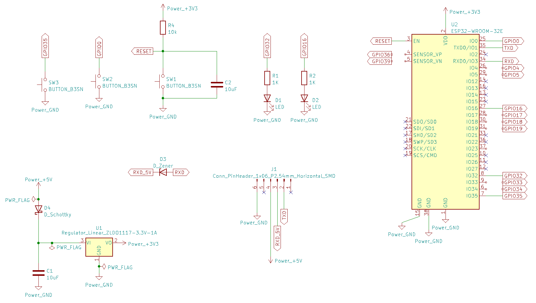
HUZZAH32 Breakout Schematic
The HUZZAH32 Breakout Schematic was very informative. I went ahead and redrew this schematic in KiCad.
Pin Charts
I made a chart to keep track of pinouts that I’ll use over several of the electronics assignment of Fab Academy. I also found Andreas Spiess youtube video on Which ESP32 pins are safe to use? very useful to understand which pins are easy to use without re-programming. Editing Andreas spreadsheet I came up with a priority 1 and 2 charts of pins to use for my projects.
Priority Pin Chart
| Priority | Pin | Arduino | Function | Note |
|---|---|---|---|---|
| A | 26 | GPIO04 | I/O | |
| A | 29 | GPIO05 | I/O | |
| A | 27 | GPIO16 | I/O | |
| A | 28 | GPIO17 | I/O | |
| A | 8 | GPIO32 | I/O | |
| A | 9 | GPIO33 | I/O | |
| B | 30 | GPIO18 | SCLK | |
| B | 31 | GPIO19 | MISO | |
| B | 37 | GPIO23 | MOSI | |
| B | 6 | GPIO34 | Input | No pullup or down resistor |
| B | 7 | GPIO35 | Input | No pullup or down resistor |
| B | 4 | GPIO36 | Input | |
| B | 5 | GPIO39 | Input |
Note: Any Pin can be used for PWM
FTDI Serial Programming Pin Chart
| Function | Pin | Arduino | Note |
|---|---|---|---|
| SW1 | 3 | EN | Reset |
| SW2 | 25 | GPIO00 | Low for programming |
| TX | 35 | GPIO01 | FTDI Serial Programming |
| RX | 34 | GPIO03 | FTDI Serial Programming |
Also note to load code the ESP32 must be put in bootloader mode. Before uploading code with a FTDI Cable connected, put it into bootloader mode by holding down the GPIO0 button SW2 and clicking Reset button SW1, then releasing the GPIO0 button SW2.
ESP32 Bootloader Mode
The ESP32 must be put in bootloader mode before uploading any type of code. With a FTDI Cable connected to provide power, put the ESP32 into bootloader mode by:
- Press and hold Switch 2 (GPIO0) hold though next step
- Clicking Reset button SW1
- Releasing the Switch 2
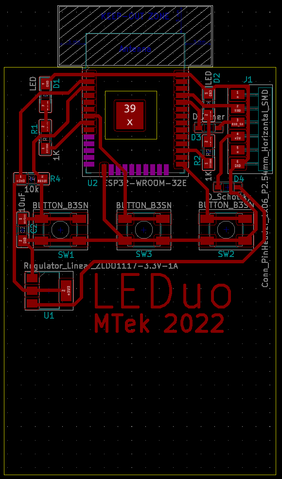
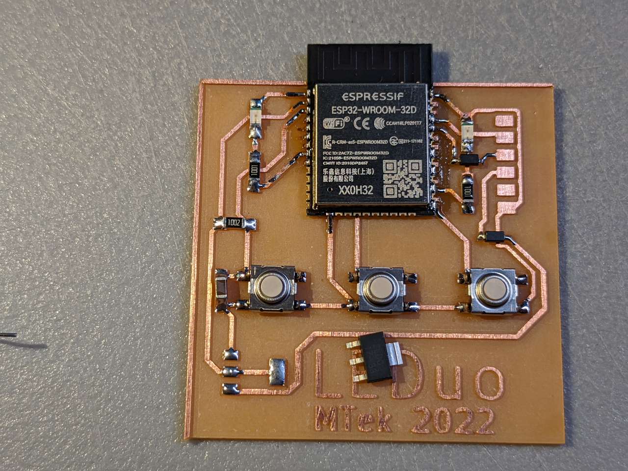
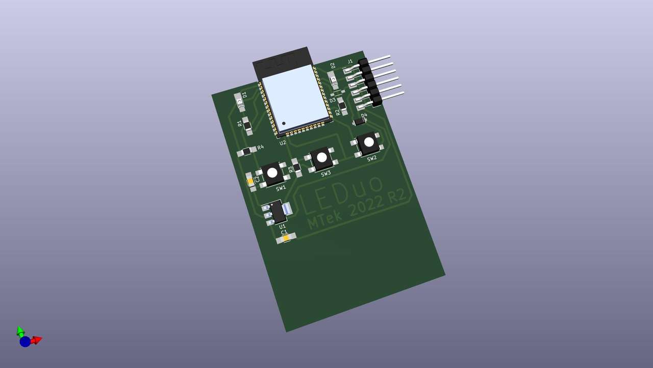
LEDuo Board
I used the PCB editor to fit a circuit with two LEDs, one programmable button, and buttons for programming and one reset. I fit all this onto one 75 x 50 cm FR1 copper clad circuit board milling blank. I also used pins that would not require re-programming, by looking at the ESP32 pin charts above.
This new board is called LEDuo!
Clean Traces in Inkscape
I wanted to develop a way to quickly process a SVG output from KiCAD in Inkscape. Here is how I did that quickly.
- Make layers: Holes, Traces, Text, BoardOutline, Unused
- Move vectors to correct layers above
- Ctrl-A to select all
- Path, Stroke to Path
- Ctrl+Shift+G Multiple times to un-group
- Turn off all layers except Traces
- Select all Traces with Ctrl-A
- Union traces with Ctrl+Shift++
- Redraw outline using snaping (magnet icon) 1.The Paint Bucket Icon (U key) “Fill bounded areas” is useful for creating objects between cut lines as well
- Boom Done !OMG so cleaned up!
- If you have text to mill, union the text separately.
- When using the “Align and Distribute” dialog, select “Move/align selection as group
PCB RGBA colors
- ffe36ece FR1 milled Yellow Tan
- e97d3dff Copper Traces
- 12121264 Holes
References: 7 Main PCB Colors: How to Select the Best One
The above may not be needed for mods. But for other CAM it helps with tool-path generation!
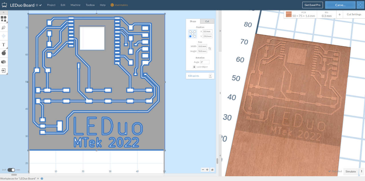
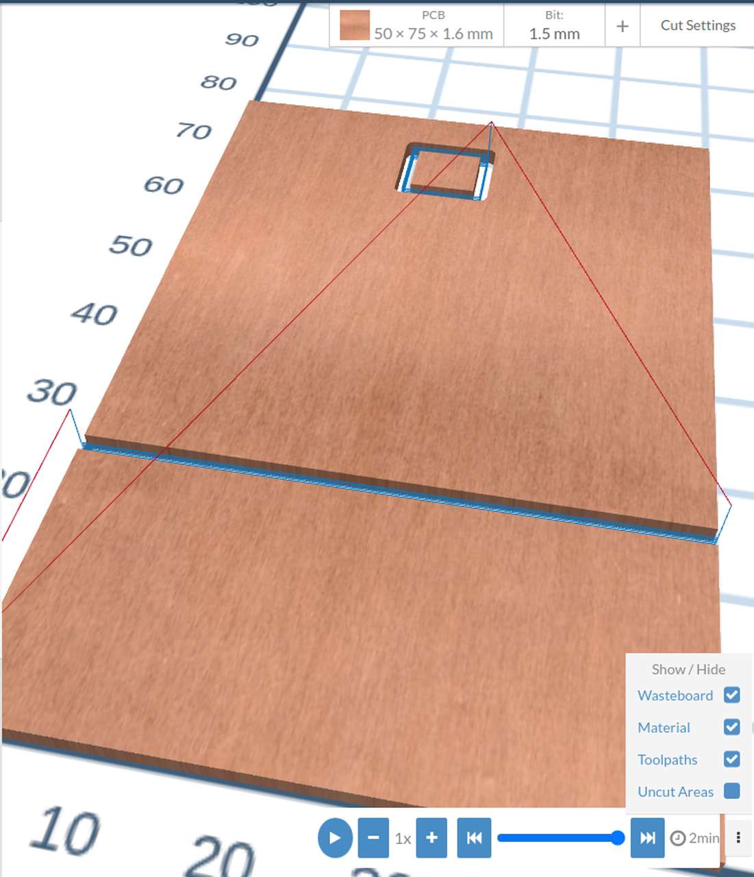
Easel CAM
Steps to mill board in Easel CAM!
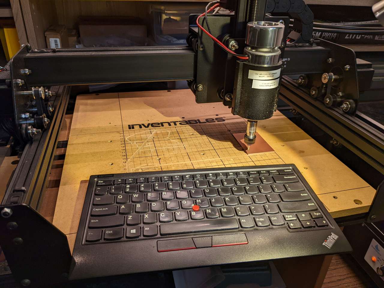 End mill zeroed and touched off.
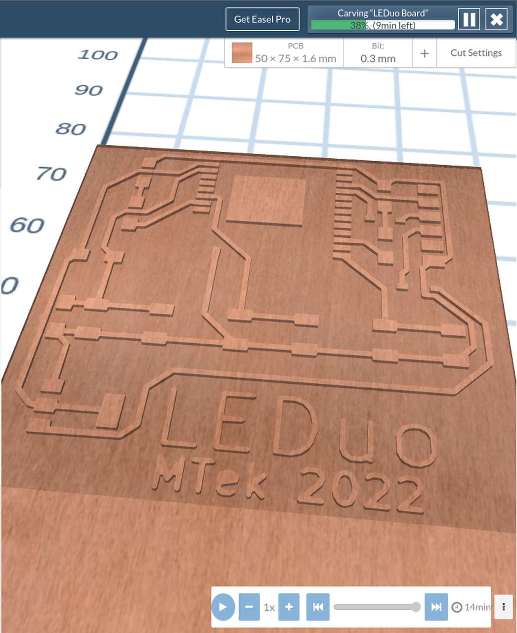
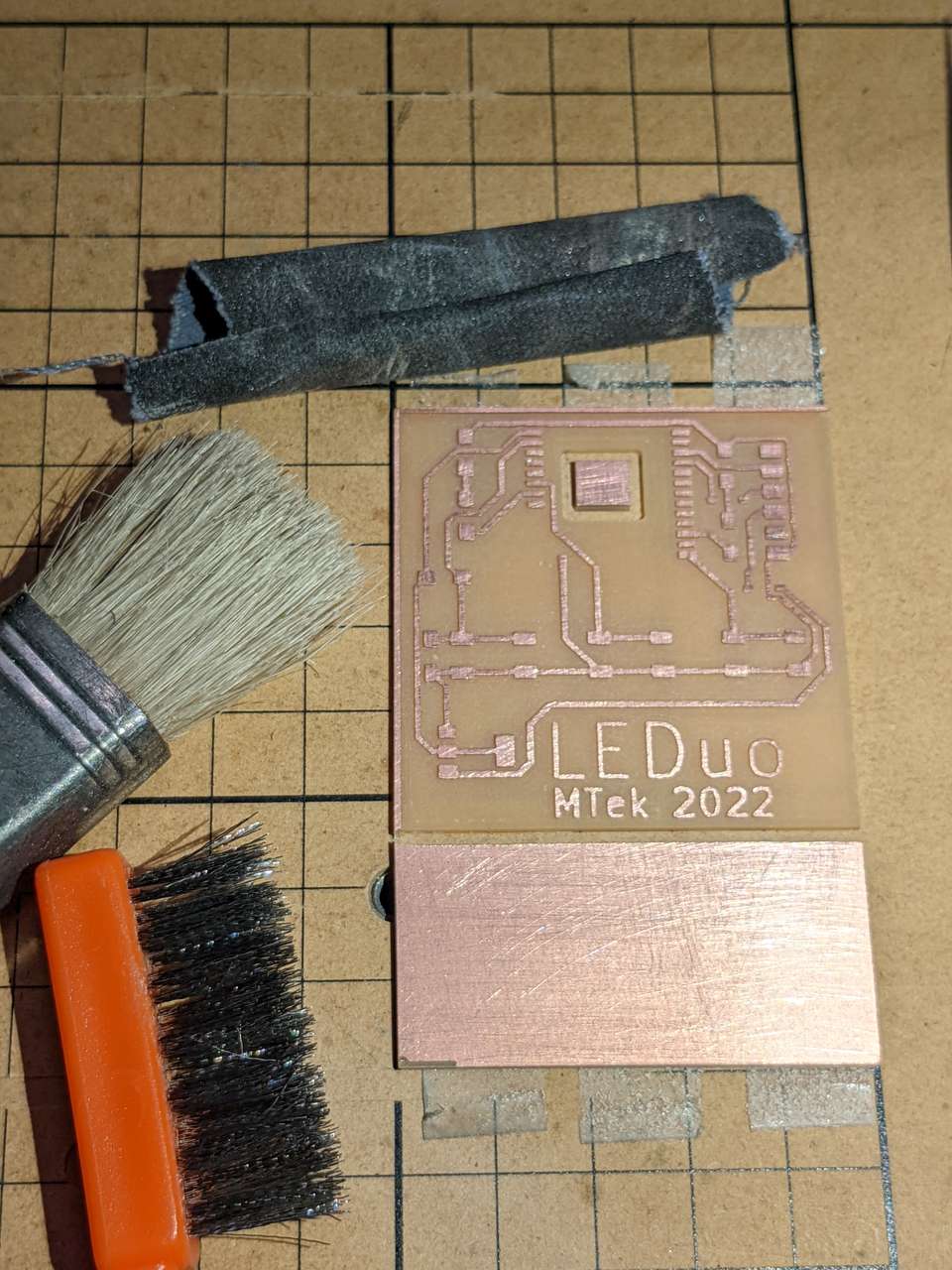
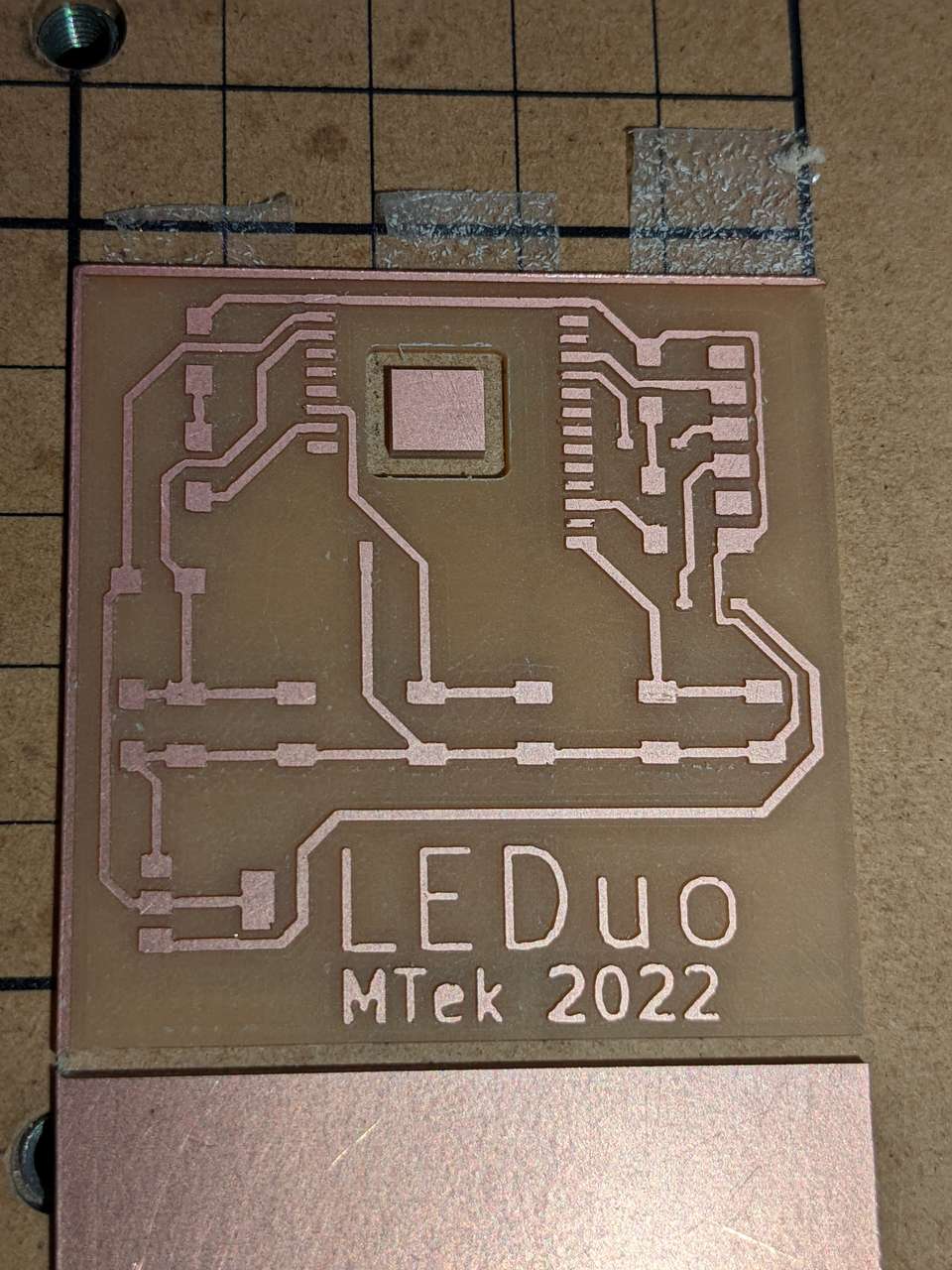
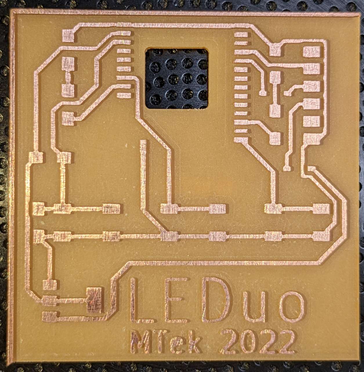 Finished board with ESP32 heatsink hole! Traces are a bit deep, will try .2mm depth next time.
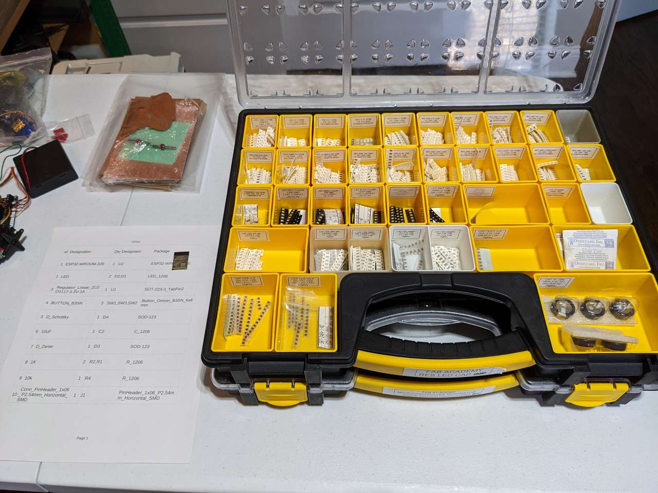
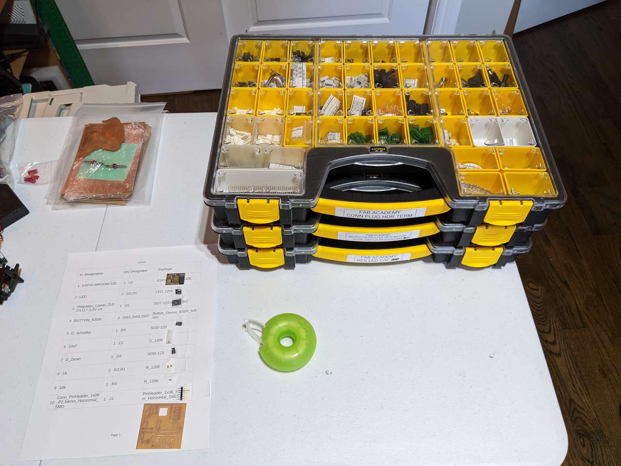
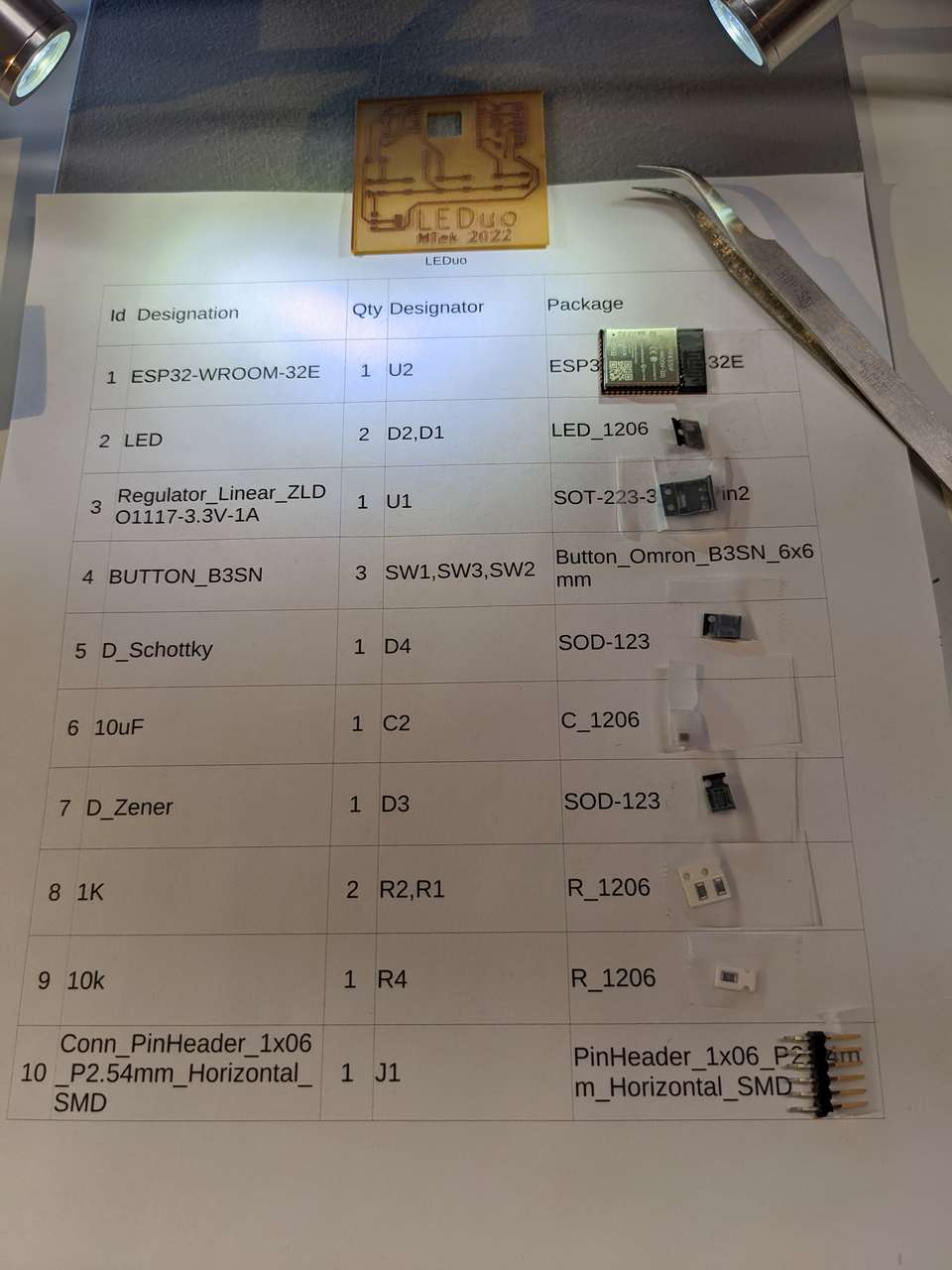
BOM
| Id | Designation | Qty | Designator | Package |
|---|---|---|---|---|
| 1 | ESP32-WROOM-32E | 1 | U2 | ESP32-WROOM-32E |
| 2 | LED | 2 | D2,D1 | LED_1206 |
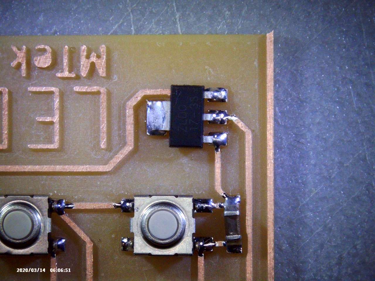
| 3 | Regulator_Linear_ZLDO1117-3.3V-1A | 1 | U1 | SOT-223-3_TabPin2 |
| 4 | BUTTON_B3SN | 3 | SW1,SW3,SW2 | Button_Omron_B3SN_6x6mm |
| 5 | D_Schottky | 1 | D4 | SOD-123 |
| 6 | 10uF | 1 | C2 | C_1206 |
| 7 | D_Zener | 1 | D3 | SOD-123 |
| 8 | 1K | 2 | R2,R1 | R_1206 |
| 9 | 10k | 1 | R4 | R_1206 |
| 10 | Conn_PinHeader_1x06_P2.54mm_Horizontal_SMD | 1 | J1 | PinHeader_1x06_P2.54mm_Horizontal_SMD |
Stuffing
From the datasheet “Soldering Pad 39 to the Ground is not necessary for a satisfactory thermal performance.” I added a hole to my board to experiment with heat-sinking the esp 32 from the back side.
I picked my SMD parts and taped them to the printed version of my BOM above.
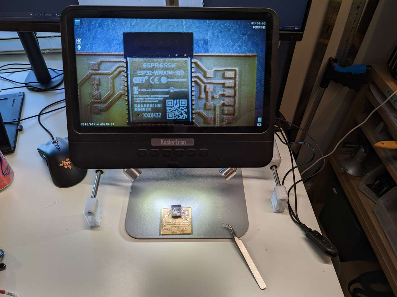
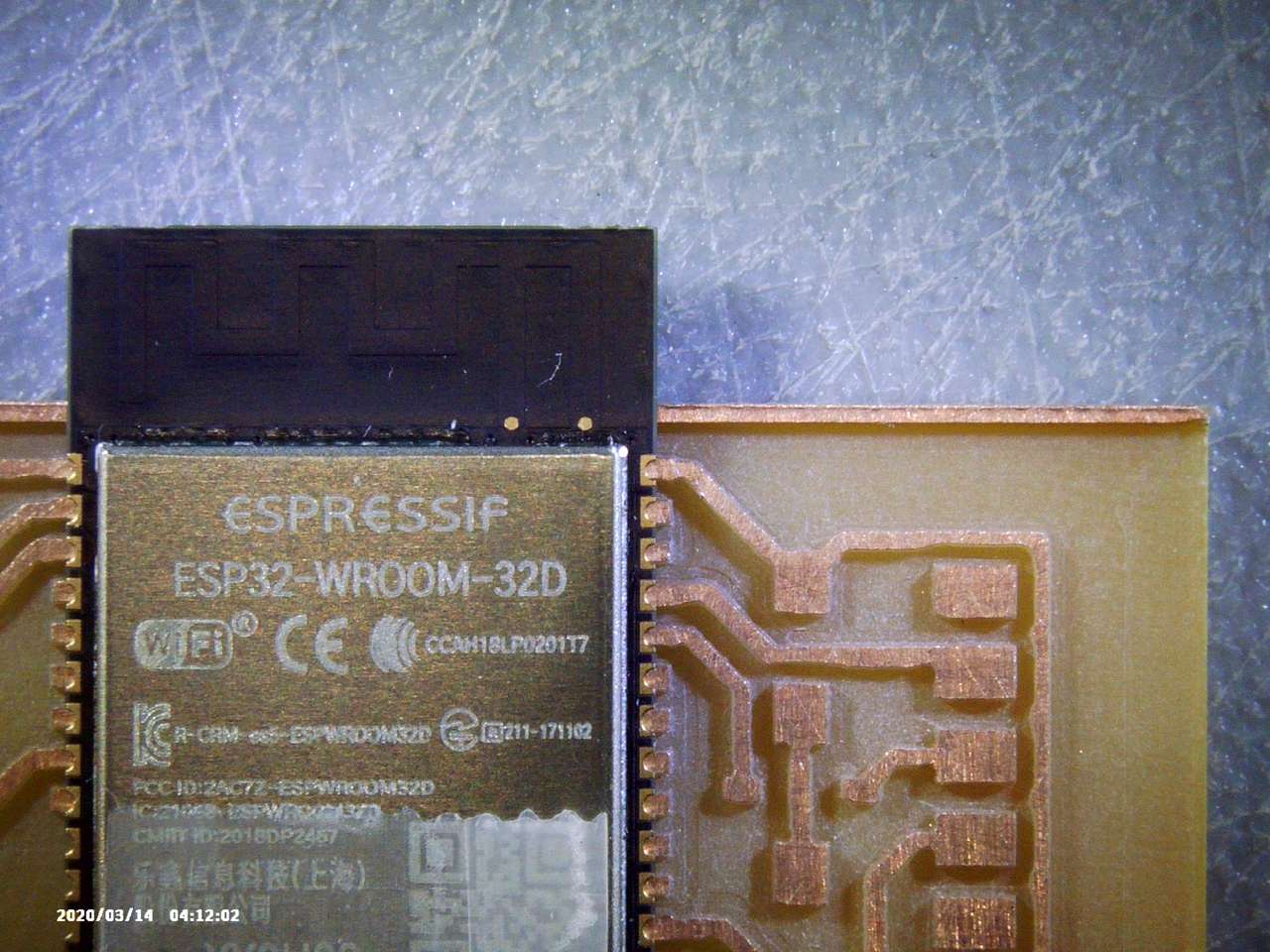
 I used my inspection microscope to make sure my ESP32 lined up with the pad correctly.
 I then soldered the parts to the board.
 I used the microscope to inspect solder joints.
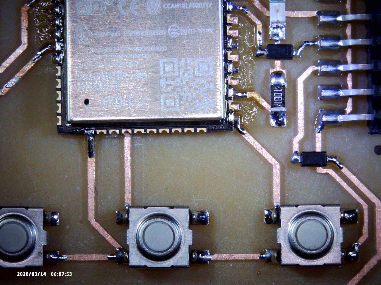 In the photo above I slipped a piece of clear plastic sheet under the unused pin of the ESP32, to prevent shorting with the trace passing underneath. In the future I will use a piece of capton tape on the back of the chip before soldering.
 Note black dot designating ground on the board.
 Next I checked mu board for shorts with a multimeter. There were no shorts. I powered up the FTDI cable with my USB hub and verified that 5v and 3vdc were present. I also felt the chips on the board to see if they were cool or warm and not hot.
Programming Board Arduino IDE
First make sure that the ESP32 module is in bootloader mode, see above under the heading ESP32 Bootloader Mode. I made sure to select Tool, Board, ESP32 Dev Module was selected. I loaded the LEDouFlashLEDs sketch below into the Arduino IDE and then uploaded my code.
int a = 0;
void setup() {
  // put your setup code here, to run once:
  pinMode(16,OUTPUT);
  pinMode(32,OUTPUT);
}

void loop() {
  // put your main code here, to run repeatedly:
  digitalWrite(16,1);
  delay(50);
  digitalWrite(16,0);
  delay(50);
  a++;
  if(a>5){
    digitalWrite(32,1);
  }
  if(a>10){
    a=0;
    digitalWrite(32,0);
  }
}
It worked and my two LEDs flashed!
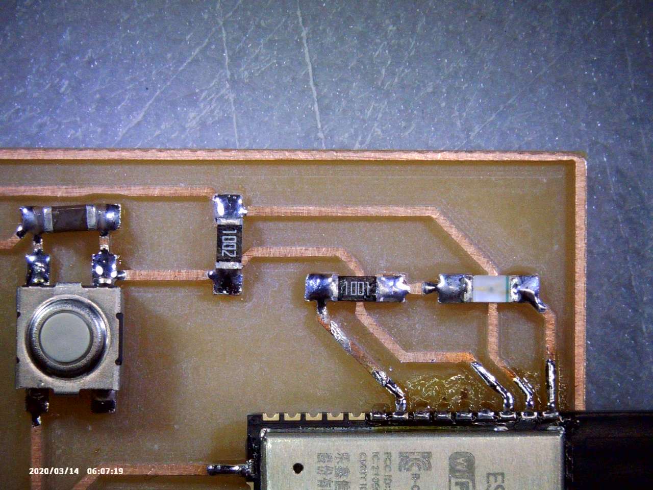
Button problems
I tried a few sketches to activate the –> LEDs of my board with a button push, but those sketches resulted in no triggering of the LEDs or odd results with the LEDs dimming and then getting bright again.
I tried the code below to see if I could see what was happening with my button.
/////////////////////////////////
// Generated with a lot of love//
// with TUNIOT FOR ESP32     //
// Website: Easycoding.tn      //
/////////////////////////////////
MTek 2022

void setup()
{
pinMode(35, INPUT);
Serial.begin(9600);

}


void loop()
{

    Serial.println(digitalRead(35));
    delay(1000);

}
This code allowed me to send a 1 to the serial monitor if the ESP32 detected a button push. Here is the output:
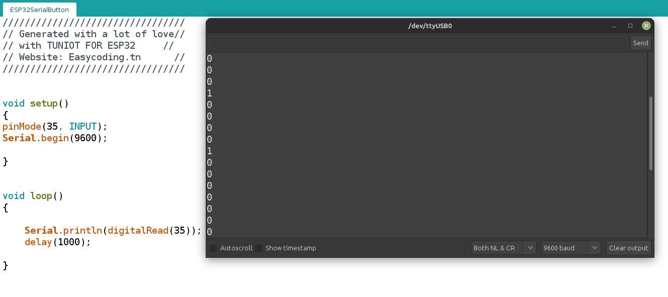 I noticed that it took me many presses of my button 35 before a 0 changed to a 1. Also the number of times a 1 appeared happened after a random number of button presses. I could not figure out what was happening, so I got help…
My instructor Blair suggested to try adding a pull-up 10K resistor leading from the GPIO 35 side of my switch to 3.3VDC. If this eliminates the button issue then I need to look into enabling the ESP32 pull-up resistor on GPIO 35. I will need to read the datasheet, or into ESP32 Arduino code to find out how to enable pull-up resistors.
I found out that the GPIO does not have the option to enable a pull-up resistor :( actually there are a few pins that cannot do this:
WARNING!!!! Pullup and Pulldown are NOT configurable on Pin D34, D35, VP and VN… they do not have internal pull-up or pull-down resistors, like the other GPIO pins. See: ESP32 Pinout Reference I noted these pins in my #Priority Pin Chart above.
This means I will need to add a physical 10Kresistor to my board to pull-up my button! Ironically that’s what the assessment says is needed. Doh!
I searched for esp32 pull-up resistor and found the following code will activate pull-up or pull-down on all other pins besides D34 and D35 ESP32 PullUp-PullDown.
Enable pullup resistor for GPIO17:pinMode(17, INPUT_PULLUP);
Enable pulldown resistor for GPIO17:pinMode(17, INPUT_PULLDOWN);
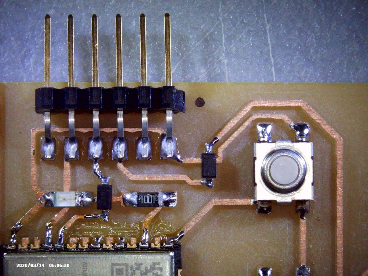
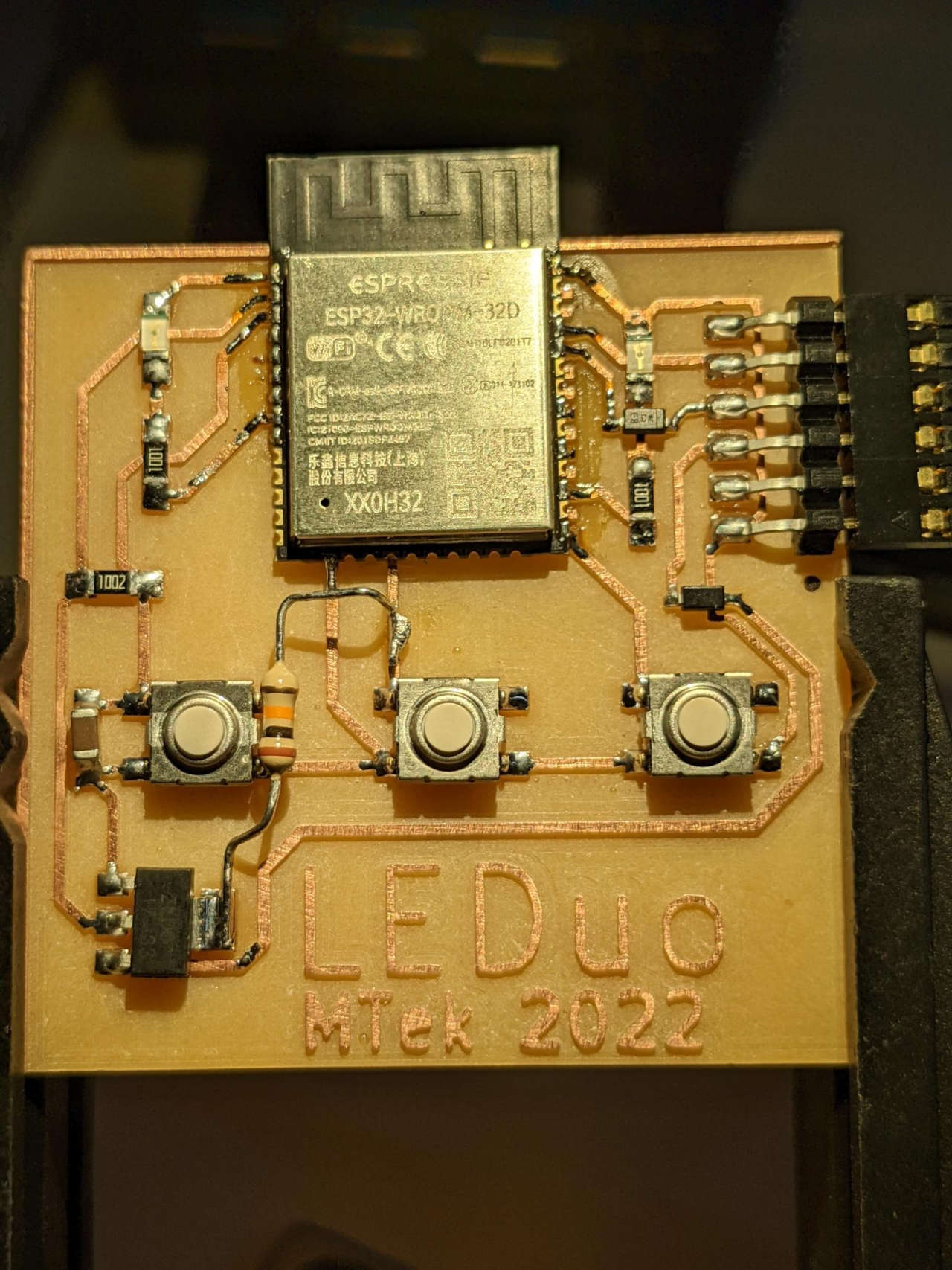 I added an old school Radio Shack 10K resistor between GPIO35 (D35 pin) and 3.3V and my board worked! What a relief!
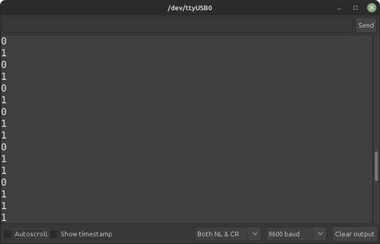 The button was very responsive and produced ones and zeros reliably using the code above.
Next I modified some code to alternate lighting up two LEDs when I pressed and released button 3.
/////////////////////////////////
// Generated with a lot of love//
// with TUNIOT FOR ESP32     //
// Website: Easycoding.tn      //
/////////////////////////////////
//MTek 2022 LEDuoLEDButtonTunoit Sketch
//Alternate two LEDs with button pressed and then un-pressed

void setup()
{
pinMode(35, INPUT); //has 10k pullup resistor
pinMode(32, OUTPUT); //LED 1
pinMode(16, OUTPUT); //LED 2

}
-->

void loop()
{

    if (digitalRead(35) == false) {
      digitalWrite(32,HIGH);
      digitalWrite(16,LOW);

    } else {
      digitalWrite(32,LOW);
      digitalWrite(16,HIGH);

    }

}
Hero Shot
 AWESOME!!!! It worked! I press the button and LED 1 turns on and LED 2 turns off, I release the button and LED 2 turns on and LED off.
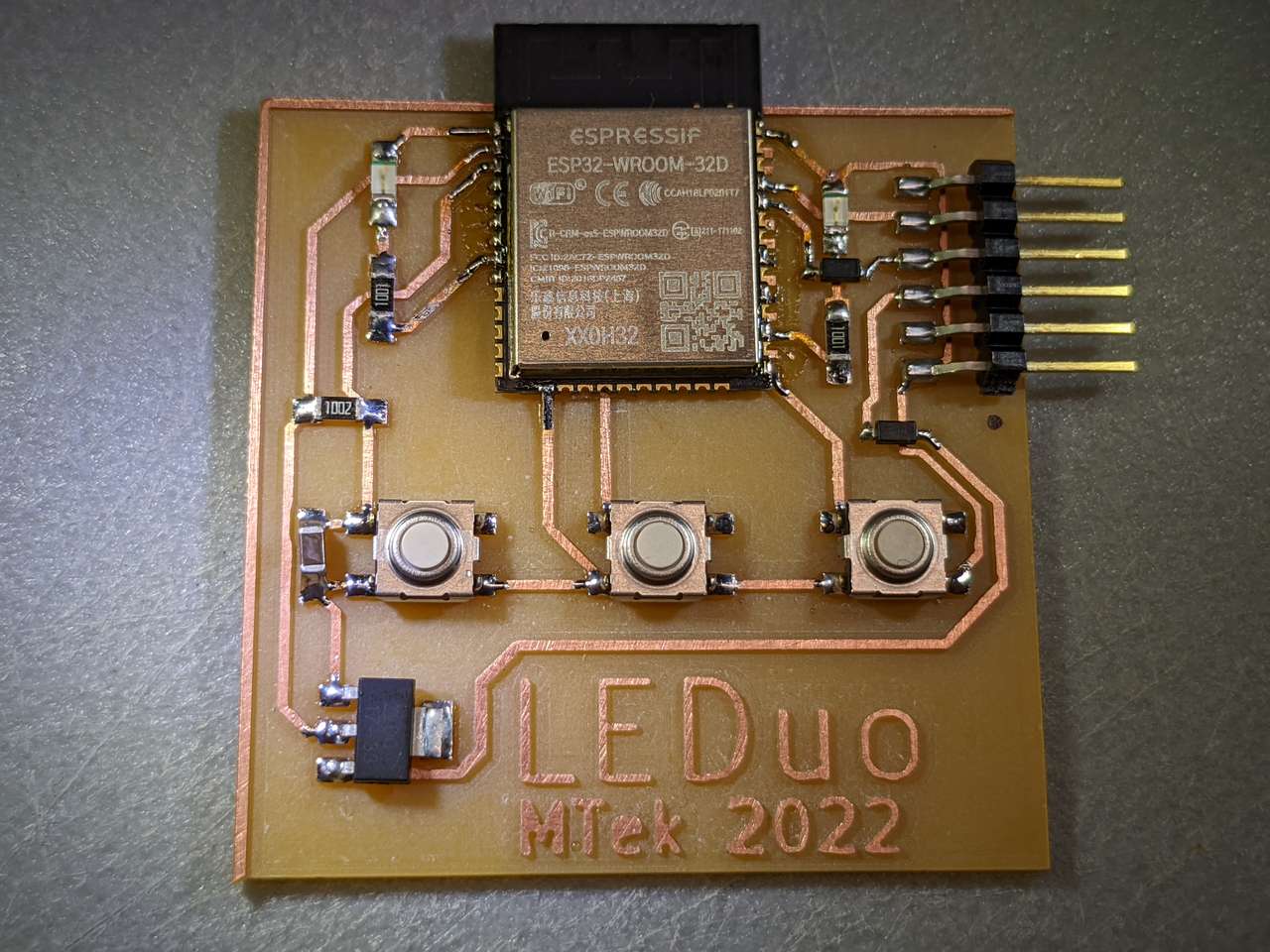
 I added a SMD 10k pull-up resistor on GPIO 35 to the R2 KiCAD design, so if someone else makes the board they don’t need to add the through board resistor on top.
CAD files
Files below require the KiCad Fab Academy Libraries
LEDuo.kicad_pro LEDuo.kicad_pcb LEDuo.kicad_sch LEDuo-brd.svg (R2 with SMD 10k pull-up resistor on GPIO 35)
Check Operating Voltage
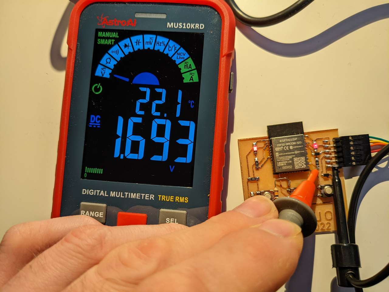
I used my new AstorAI MUS10KRD multimeter to check the operating voltage of a few different parts of my LEDuo Board.
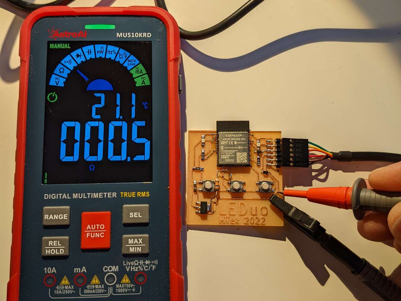 First I made sure my leads were working properly by using the continuity test on my multimeter, the meter emitted a beep and lit up the continuity light.
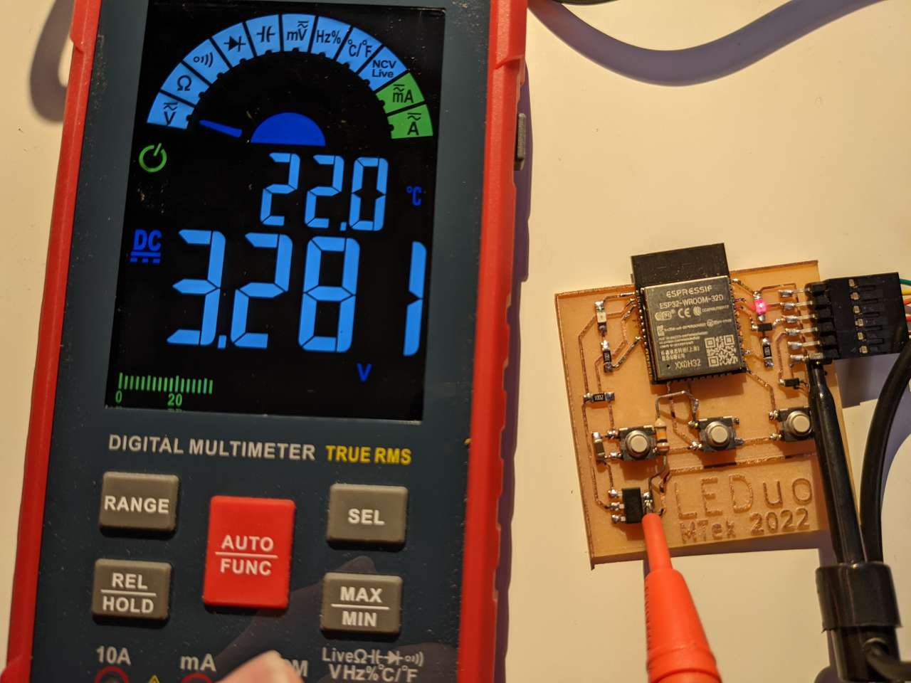
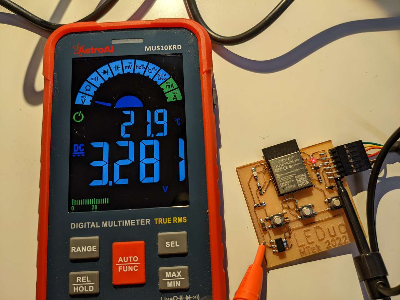 Next I pressed the Func button until I was selected DC voltage and checked the voltage on the regulator. 3.281 VDC, very good it’s a 3.3VDC line!
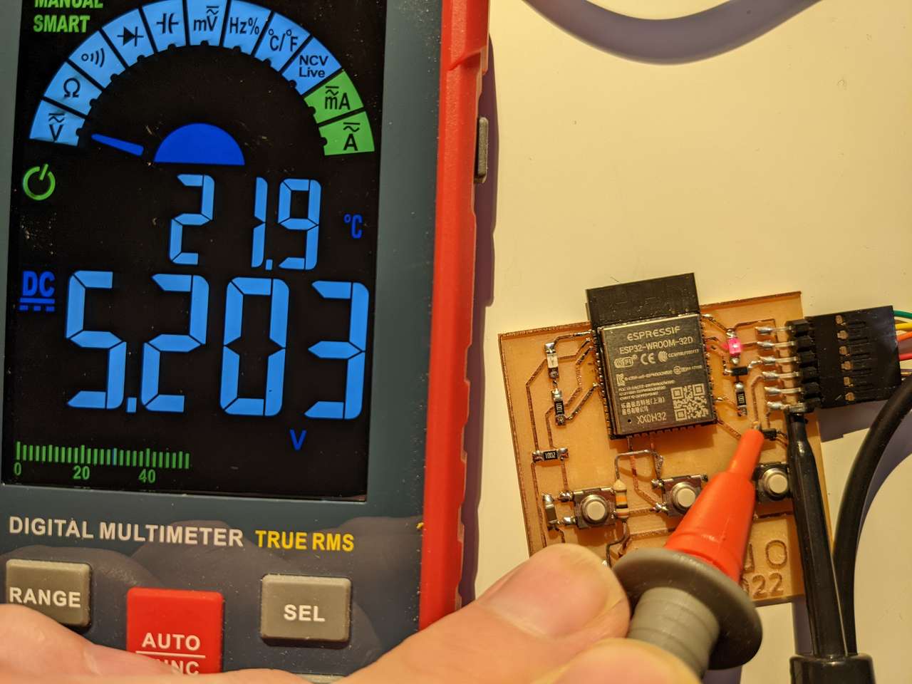
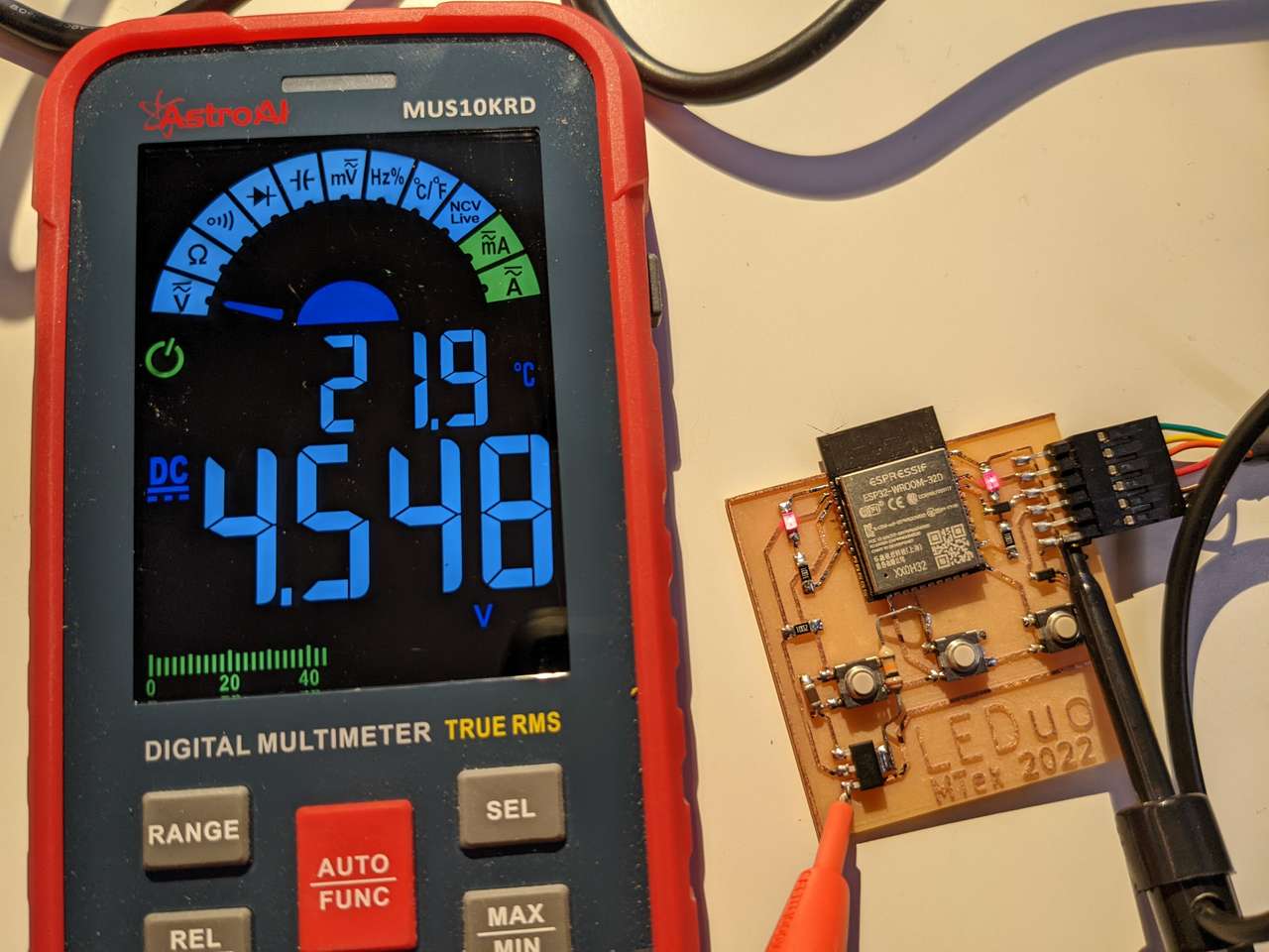 Then I went around investigating various traces and pins. Hmmm… this one is 4.548 should that be 5VDC, well it must be ok my circuit is working fine.
 Hrrmmm! Yep this is 3.281 again here and it’s also the 3.3VDC line
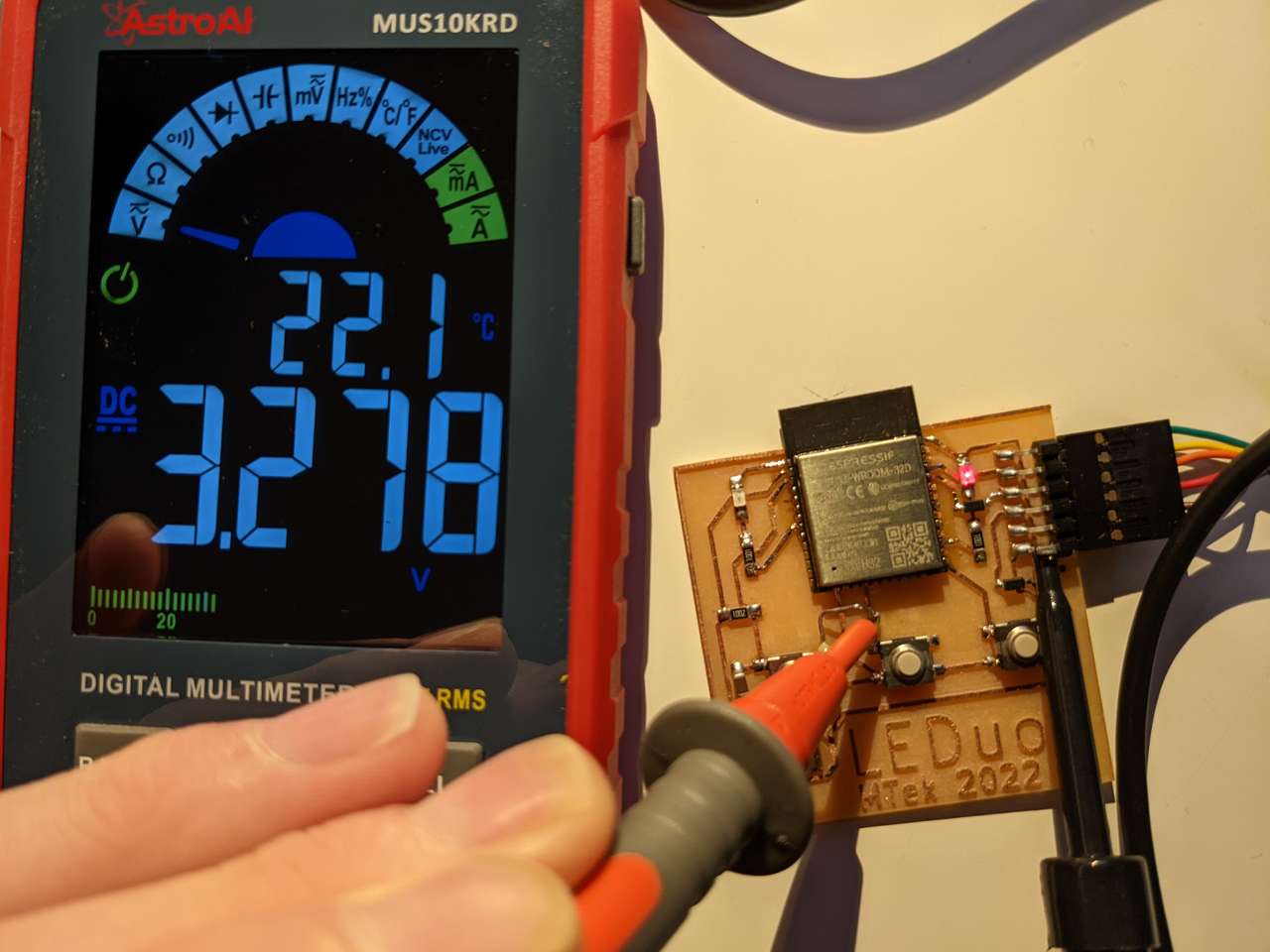 Hummy! This one is 3.278VDC, a bit of a drop after the going through the resistor.
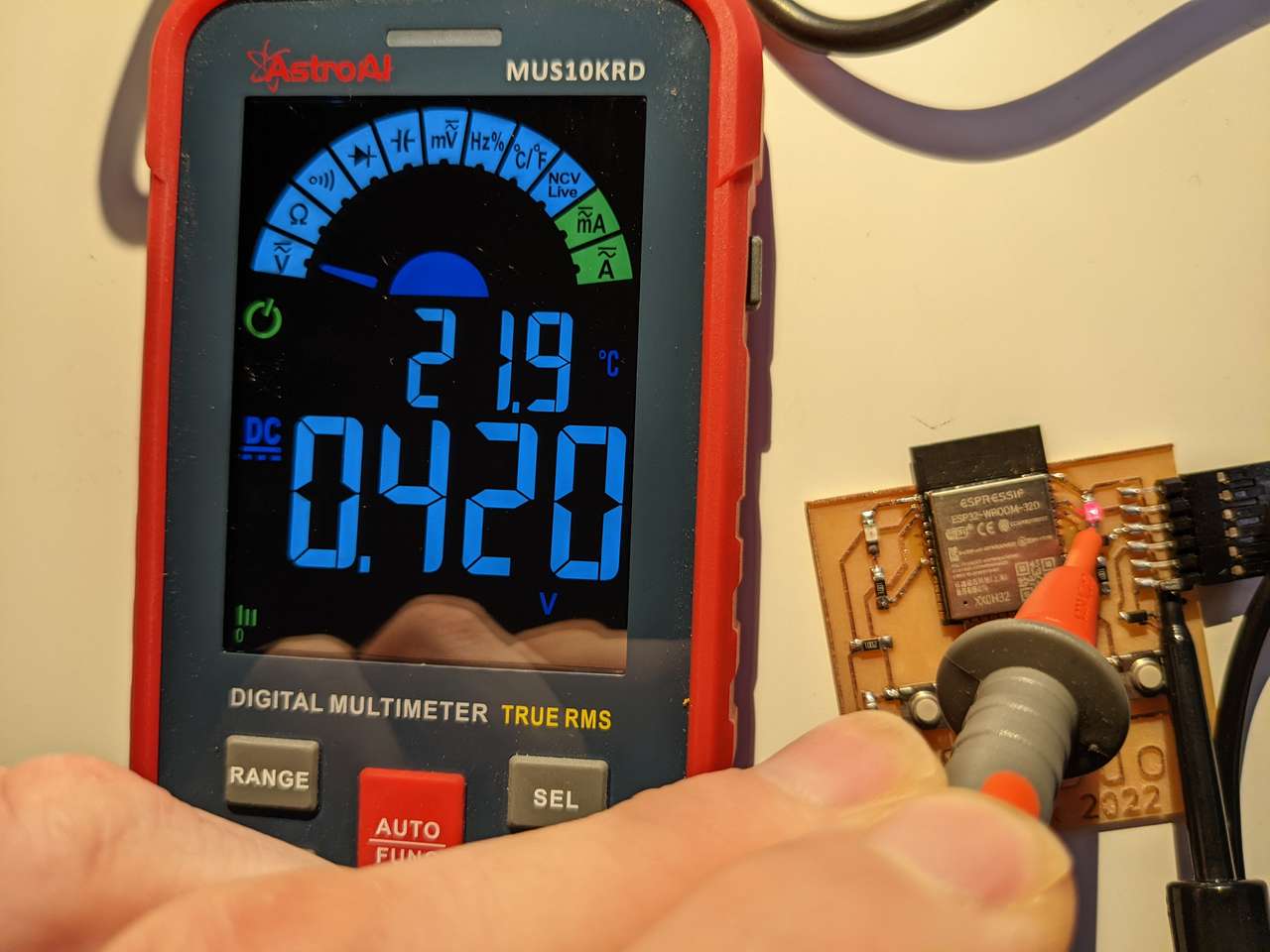 Weird! This one is low and erratically reading swinging voltages, due to the fast blinking LED, maybe I need and oscilloscope to read this better?
 Hrrrm. this voltage is bouncing around too, it’s the resistor that feeds the LED.
 Yowza! This is the higest voltage I’ve read so far, oh yes that makes sinse it’s the 5VDC line coming directly for the FTFI cable!
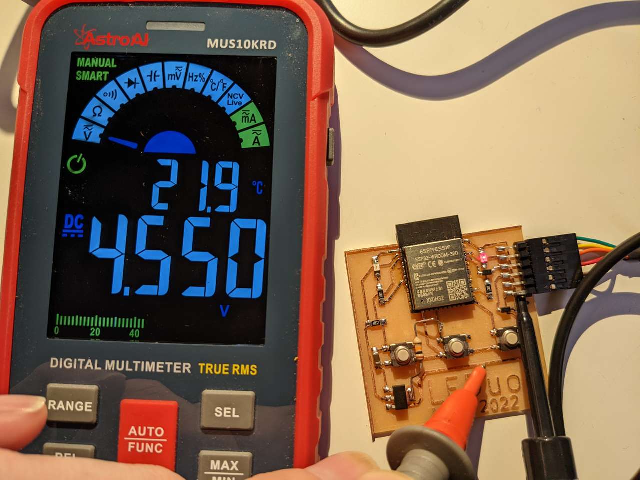 Wheezy Cheesey Chicken Breezey This voltage is trying to make it up to 5 but it reads 4.550VDC
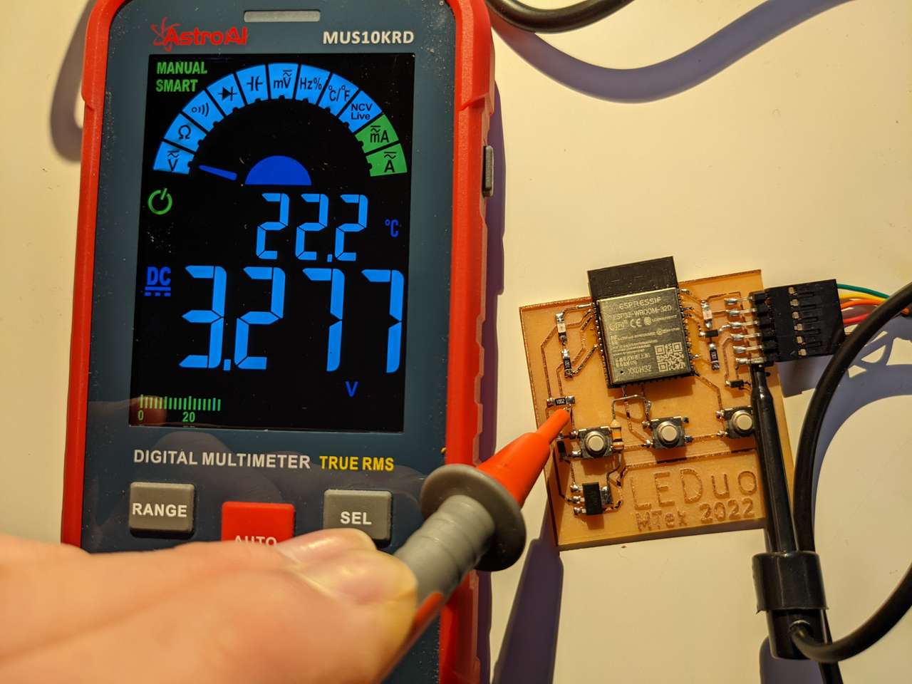 Resistance if futile! After this resistor the voltage is 3.277VDC.
It’s fun probing around a circuit and checking voltages!
Check Board with Oscilloscope
I used the SparkFun Electronics How to Use an Oscilloscope video to get me started with the Oscilloscope I have. I have never really used an Oscilloscope before, but I have seen others use one and understand the basic reason for using one. Specifically helpful for me to learn my Tektronix TDS 1002 oscilloscope are these documents: Really great video to help me learn all the knobs and buttons: Tektronix Oscilloscope Tutorial Part 1 The original manual for my model of oscilloscope was great too!: TDS1000- and TDS2000-Series Digital Storage Oscilloscope hosted by Neurophysics Lab at UC San Diego
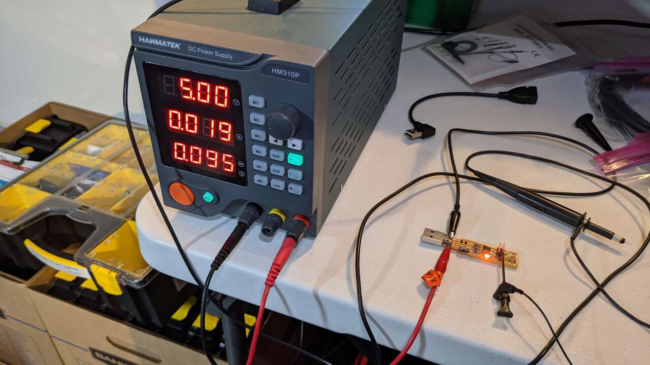 Lab power supply at 5vdc
 Leads for 5vdc test
Check noise of operating voltage
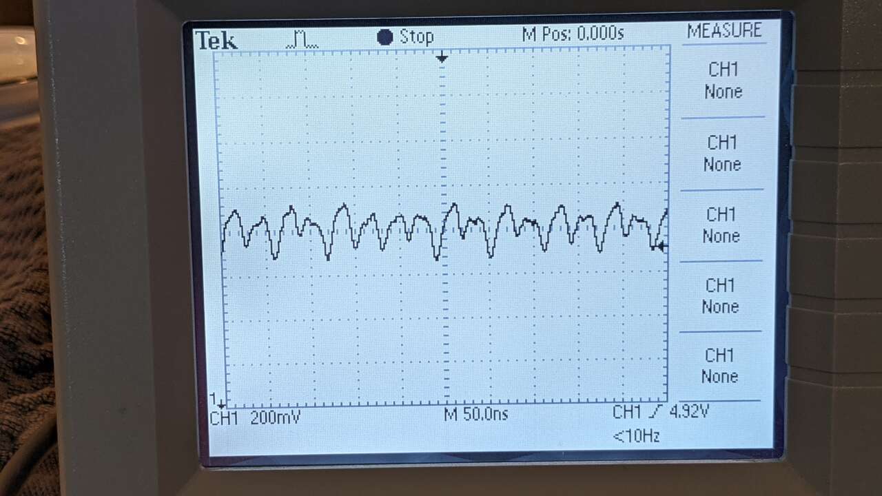 O-scope reading of 5vdc from lab power supply, at this point I have learned how to zoom in on curves and move horz and vert. I am very zoomed in at 200mV per grid.
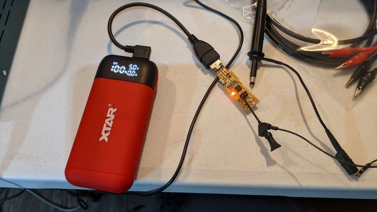 Let’s try and see if the 5vdc from this xtar 18650 USB power bank look any different.
 Yep it looks different, a little wider 5vdc sweep, but not much more sweep at all, I am very zoomed in at 200mV per grid.
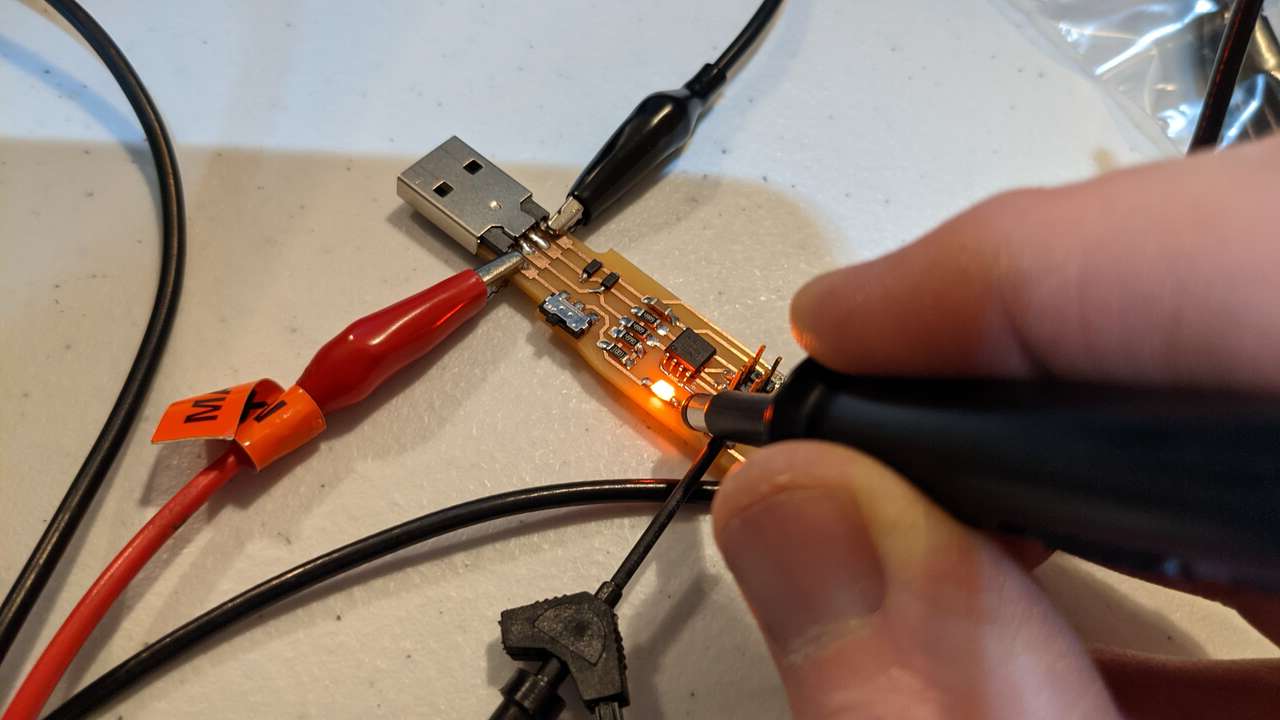 Let’s try measuring this point just after the ORG LED.
 Here is the reading, I learned how to move cursor at this point. The reading is 3.28V at the cursor.
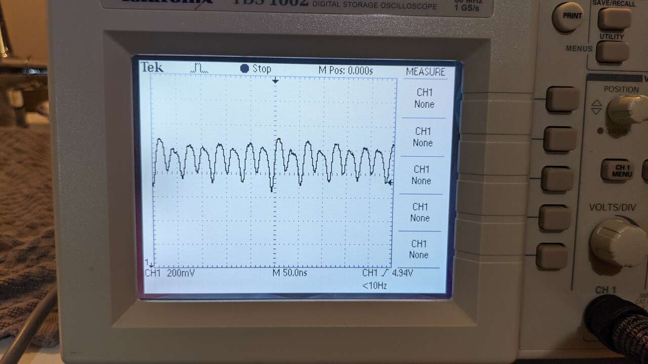
 What’s the voltage on the pin 2 of the MCU?
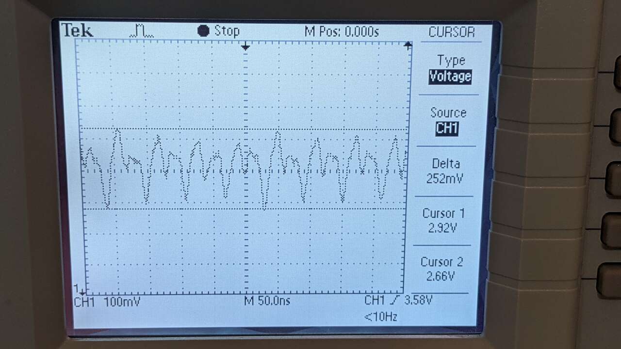 Here I learned how to move two cursors and I zoomed in to 100mV per grid section. Delta is 252mV, Max 2.92V Min 2.66V
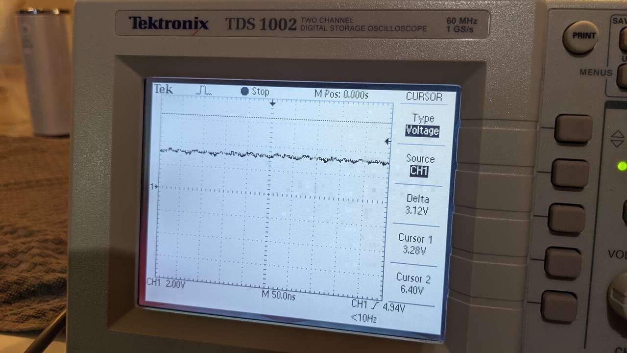
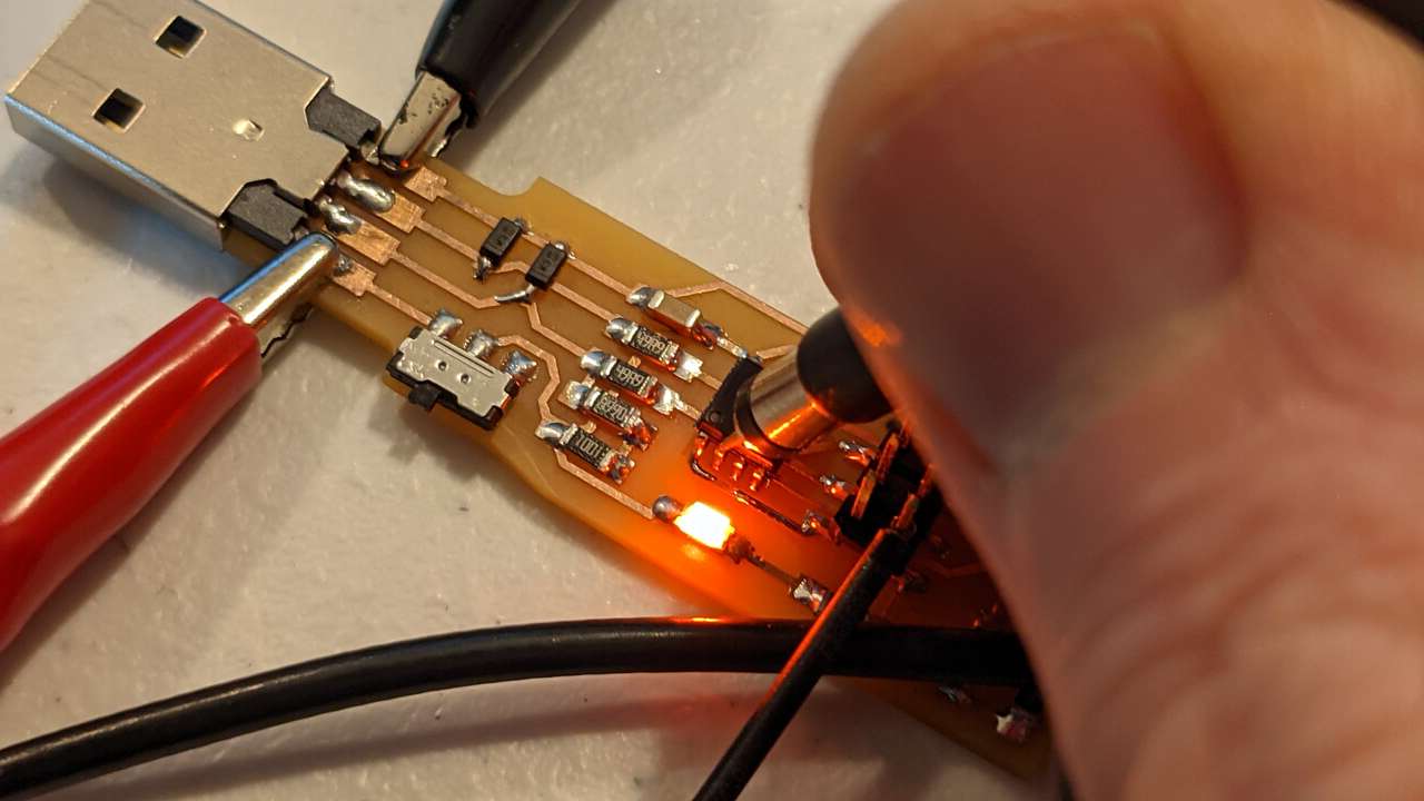
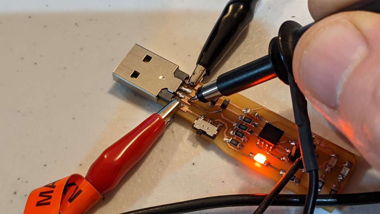 Let’s measure the voltage at this pad on the USB
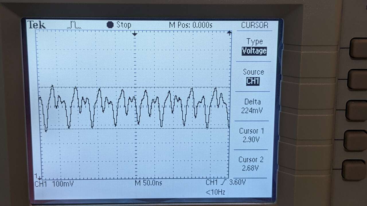 Delta is 224mV, Max 2.90V Min 2.68V
Interpret a data signal
I just purchased the low cost $180 Miniware DS213 Oscilloscope for our Fab Lab. This is my first time measuring signals on an Oscilloscope, let’s see what happens! I watched the video Tutorial. DS213 Oscilloscope to learn.
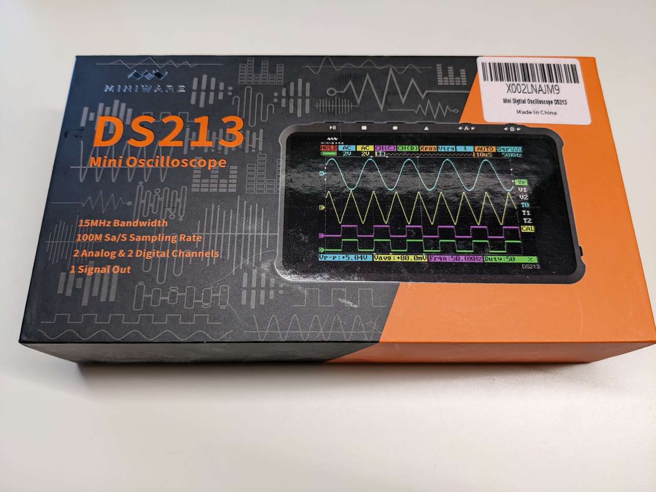 Box
Box
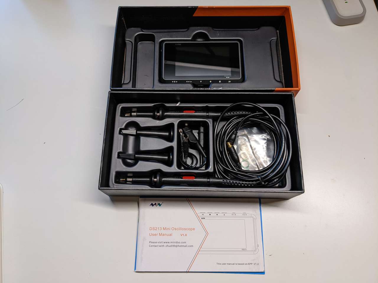 Inside box
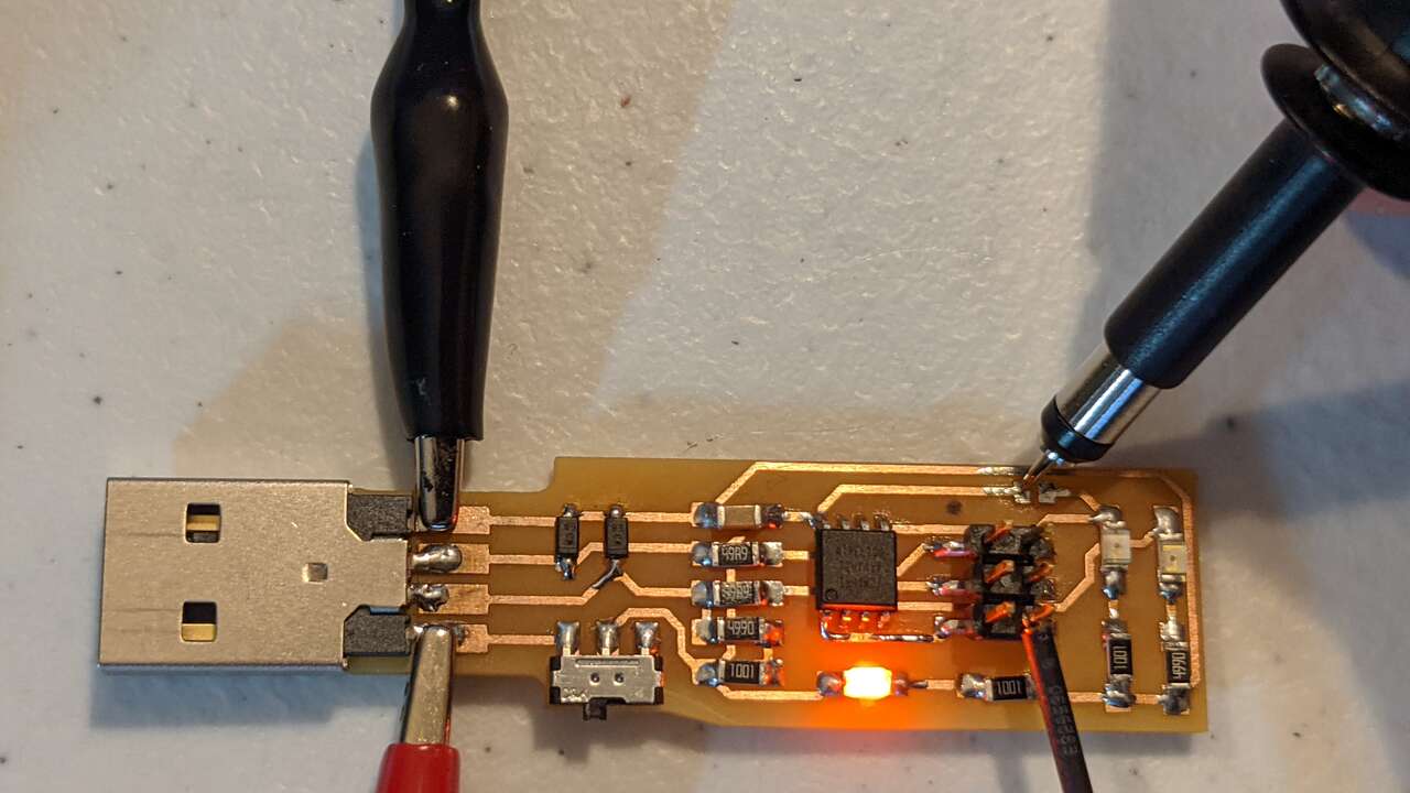
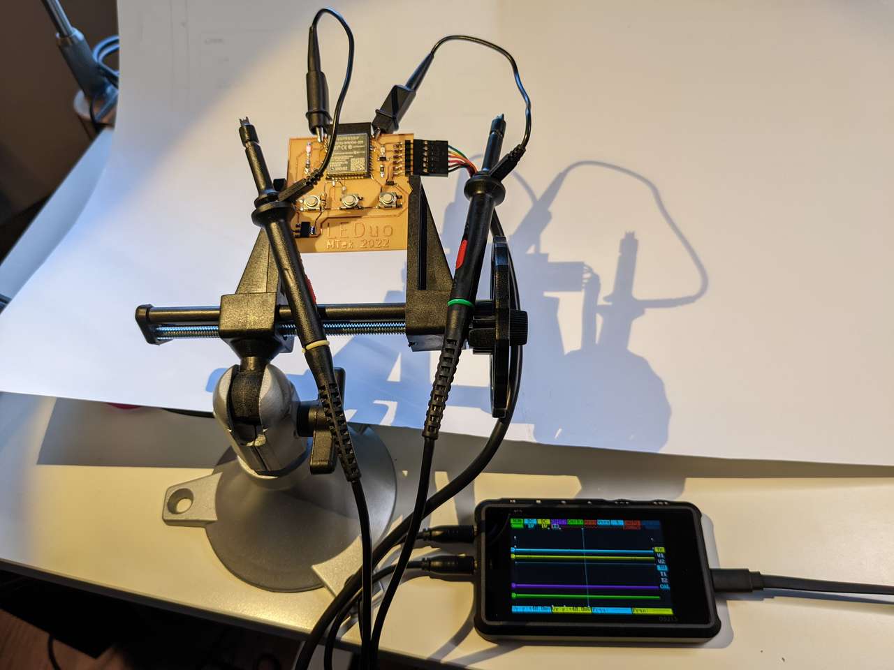 Ground and probes connected my LEDuo board.
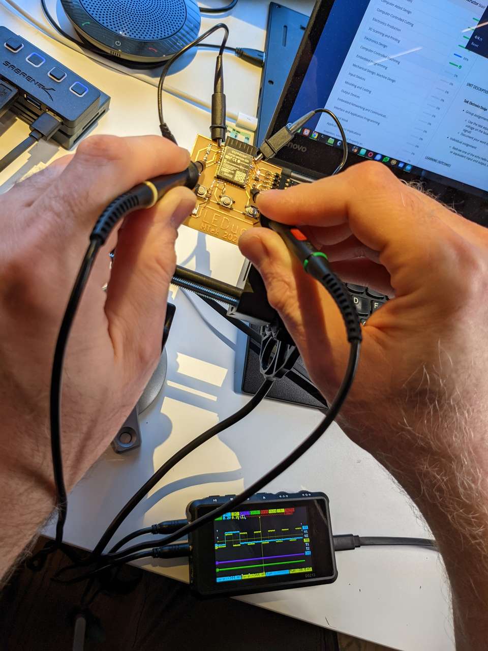 Probing LED outputs.
I set the CHA and CHB to DC, and the horizontal grid to 0.2V for both channels. I moved CHA and B to a point in the middle bottom of the horizontal trigger line. I changed the vertical grid to 50ms
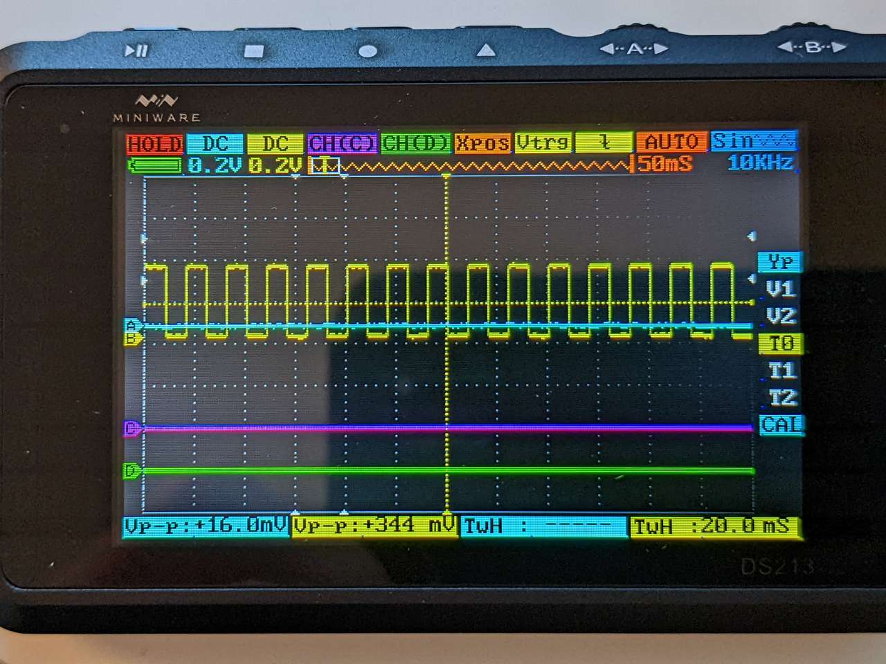 In the photo above you can see Channel B (Yellow Line) TwH (Time Width High) is 20.0ms, this means the LED on Channel B is on for 20.0 ms.
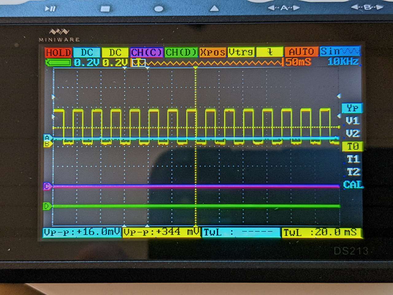 In the photo above you can see Channel B (Yellow Line) TwL (Time Width Low) is 20.0ms, this means the LED on Channel B is off for 20.0 ms.
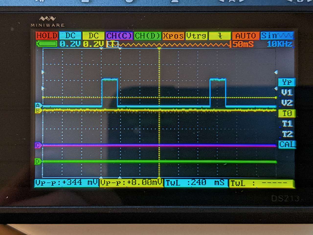 In the photo above you can see Channel A (Blue Line) TwL (Time Width Low) is 240 ms, this means the LED on Channel A is off for 240 ms.
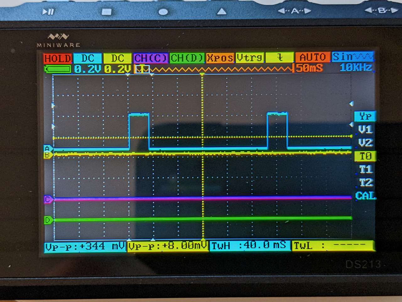 In the photo above you can see Channel A (Blue Line) TwH (Time Width High) is 40 ms, this means the LED on Channel A is on for 40 ms.
Using the Oscilloscope is a great way to check to see if the code I loaded on my board is doing what it was commanded in the real world.
The Miniware DS213 Oscilloscope works great! Also it’s limited options makes it less intimidating than more featured packed Oscilloscope.
Notes
I was a bit freaked out by this weeks assignment, I haven’t done any electronics CAD design before except for modifying existing eagle designs. Oddly I have fabricated a milled 555 timer circuit for a circuit bending workshop led by Patrick McCarthy back in 2011. Our 555 timer circuit was designed and fabbed hacker style skipping eagle or other circuit design software completely by using the following steps:
- Hand draw circuit based on point to point wiring of 555 timer circuit used in previous circuit bending workshops
- 3D modeling this circuit in SolidWorks (which allowed easy graphic customization)
- Exporting the 3D CAD file to a 3D DXF file
- Importing the 3D DXF file into Modela MDX-20 carving software (on Windows XP or 7?)
- Milling the circuit on the Modela as if it were a regular milling job.
- Milling a total of 20x boards for our Circuit Bending workshops.
Fast forward 9 years later and my goals for Electronics Design in our Fab Lab is motivated by:
- Open source software design and fabrication process flow
- Easy 1st and 2nd electronics design experience for students who have just learned Tinkercad
- Simplify the design process, but still learn concepts for advanced electronics cad (Kicad or eagle cad)
- Make the process of milling a board easy (X-Carve or MDX-20)
- Keep the design to fab time 1 hour max (with support from fab lab staff for the 1st yellow belt level)
- Keep the design to fab time for second board to 2 hrs max (orange or green belt)
Could I use some of the techniques above for this weeks work? It has always seemed over kill to use eagle to make single sided circuit boards. I do think that milling circuit boards is pretty fun, but the design process and electronics design software has been a steep learning curve for me and may be for my students. This week I want to explore how to scaffold learning of electronics design. I would prefer to go from hand drawn sketches to a milled board in way that still allows students to learn the concepts needed for more advanced electronics design later.
Looking at 2019 Fab Academy students work revealed that others have followed similar processes. I found the following student pages the most informative via the google custom search on Neil Gershenfeld’s The Fab Academy site
Eagle CAD Tutorial 3. 2019 Eagle CAD Tutorial
Exploring Other Worlds
Beyond assessment requirements
Block Coding for ESP32
Next I researched some other ways to program my ESP32 based LEDuo board. It has been some time since I have programmed in C++ for example and I had a very difficult time even back then. So I wanted a way to block code in C++, well I found not only a C++ block code editor for the ESP 32, but two of them:
| Code Base | Name | Author | Type | Cost |
|---|---|---|---|---|
| C++ | TUNIOT Code | Adel Kassah | Web / Local | Free / $25 |
| Micro Python | EduBlocks on the ESP32 | Chris Dell | Local | Free |
I tried TUNIOT Code first. Adel has a great playlist of videos on the ESP32 I will play more with block coding in future assignments. Time to move onto next weeks assignment.
Other EDA CAM
Using Carbide Copper CAM
I decided to try a new CAM software Carbide Copper Carbide Copper is web based and has a intro video to help get you started. Here is a summary:
- Define your board size
- Upload Gerber files from KiCAD! No need to export SVG files and clean them up!
- For some stupid reason KiCAD does not allow you to mirror your top copper layer so you can mill! How dumb!
- Carbide copper wont let you flip the file either!
FlatCAM
I also tried FlatCAM, Free and Open-source PCB CAM. FlatCAM I installed the using the latest source. This was a pain in the ass so I stopped and will come back later.