13. Input devices
Assignment
individual assignment
measure something: add a sensor to a microcontroller board that you have designed
and read it
group assignment
probe an input device’s analog levels
and digital signals
My Assignment Plan
I will make a ESP 32 board that reads both a potentiometer and a hall effect sensor mounted in the same geometry RC control sticks. I will then measure and compare these two inputs. Maybe I will graph the output so the resultant smoothness can be compared. ~~I may make my ESP32 chip un-plugable from my board (buying pins and headers to do this costs more than an entire ESP-32 Chip, not cost effective).~~
- Design ESP-32 based board with 4 gimbal inputs.
- Design one sub-board that duplicates or improves gimbal performance using Texas Instruments DRV5055A3Q1 can run at 3.3 or 5vdc (Q1 series has higher temp range)
TX12 and TX16 RC Transmitters
I have some spare Jumper Brand Hall and Pot Gimbals in my workshop, here is what they look like:
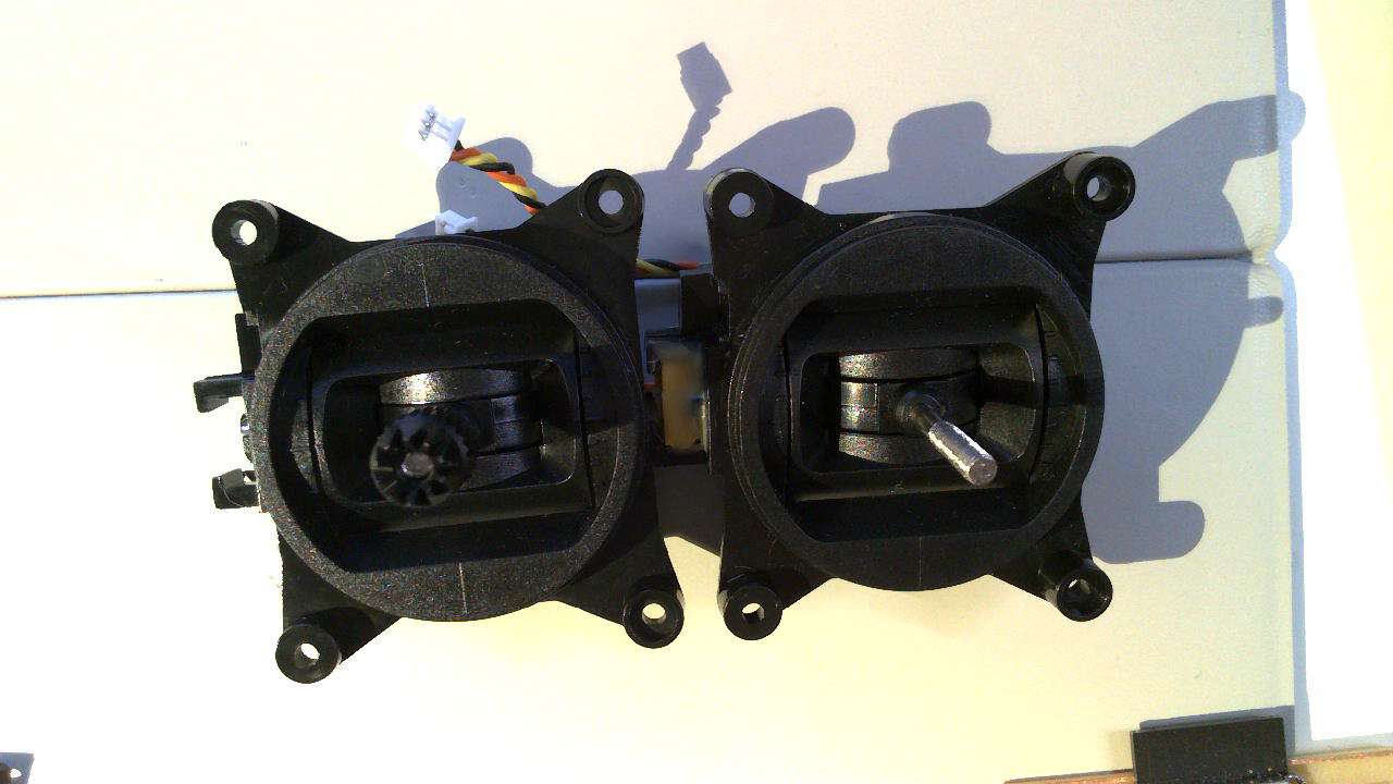
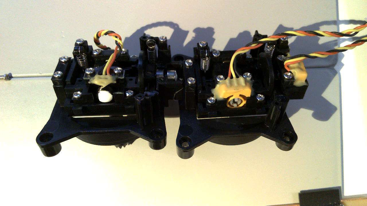
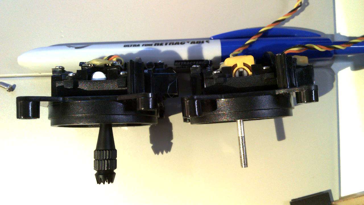 Images above show the differences between the hall (left) and potentiometer (right) gimbal sensors.
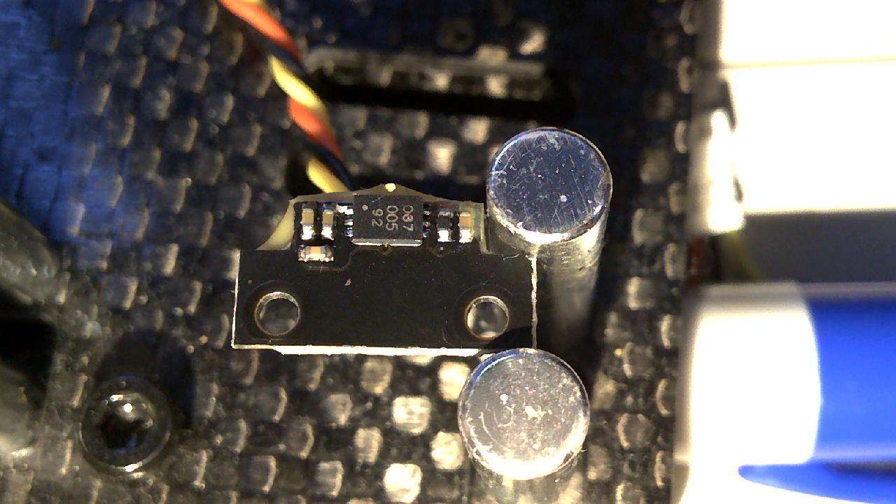
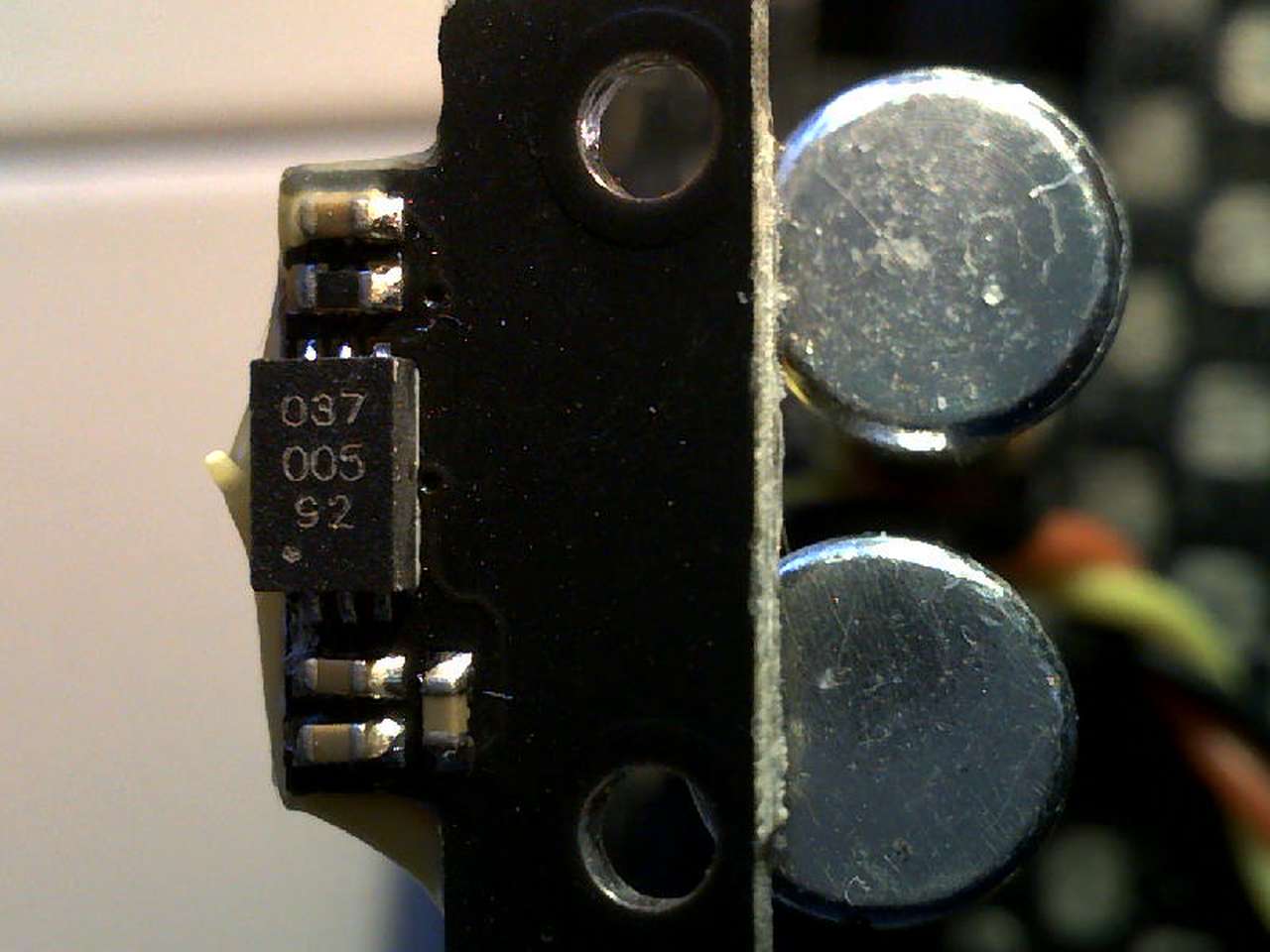 Unscrewing the hall effect sensor board from the gimbals revealed a chip marked 03700592. It ends up this chip is most likely a Allegro A1392SEHLT-T with a 2.50 mV/G Sensitivity.
I searched for this number and no results came up. However a search for the common chips used in RC controls did result in lots of information.
It seems that the Allegro A1388LLHLX-2-T hall effect IC is widely used as the hall sensor in most modern hall effect gimbals as of 2022. See links below:
OfficalEdgeTXDiscussionThread “They use the same Allegro A1392 hall effect IC, as e.g. the original RadioMaster hall gimbals (V1 to V4 and also AG01).” The AG01 is a $60 a piece gimbal that is highly regarded as one of the best gimbals on the market. so it seems a Allegro A1392 is an upgrade over the A1388 chip.
This RC Groups discussion has details on the exact gimbal sensors I have. Here I summarize the important notes from this discussion:
- The 100k resistor forms a potential divider with the input resistance of the Vref pin of the 1391 chip that reduces Vref to 250/(250+100)x3.3 = 2.36V
- The minimum allowable Vref on the datasheet is 2.5V
- There is a footnote on the specifications relating to Vref that says :”Degradation in device accuracy will occur with applied voltages of less than 2.5 V”
- The input resistance of the Vref pin decreases with temperature, further lowering Vref as temperature increases
- The change in output with temperature is far less stable at Vref=2.5 to 3V than it is at 3 to 3.5V (see relevant graph below) - goodness knows how it behaves at 2.3V!
- A tiny correction to @Mister_G report above - the datasheet of Allegro A1392 (page 3) says, MINIMUM 250 kOhm, thus the value and the deviation from positive supply rail on Vref pin can be a bit less than the worst case value listed here in the calculations.
RadioMaster TX12 HALL gimbal
Pinouts
Jumper Hall Effect Gimbal Info and Pin outs see Post #6
 This photo shows the typical wire color meaning, but always check your wires to be sure.Source
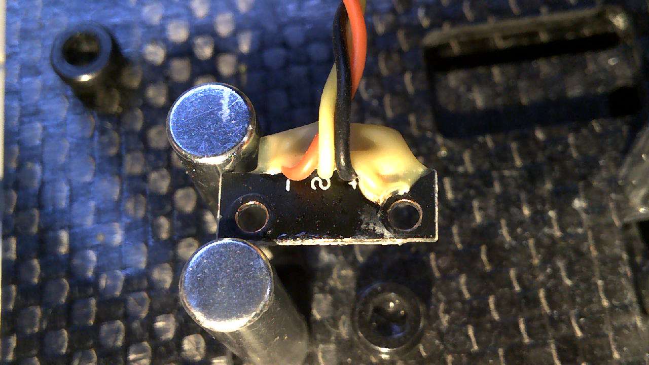 On the back of my hall sensor board I can see the -,S,+ markings.
 This shot shows the traces on the front side of the board and the vias leading to the wires on the back side.
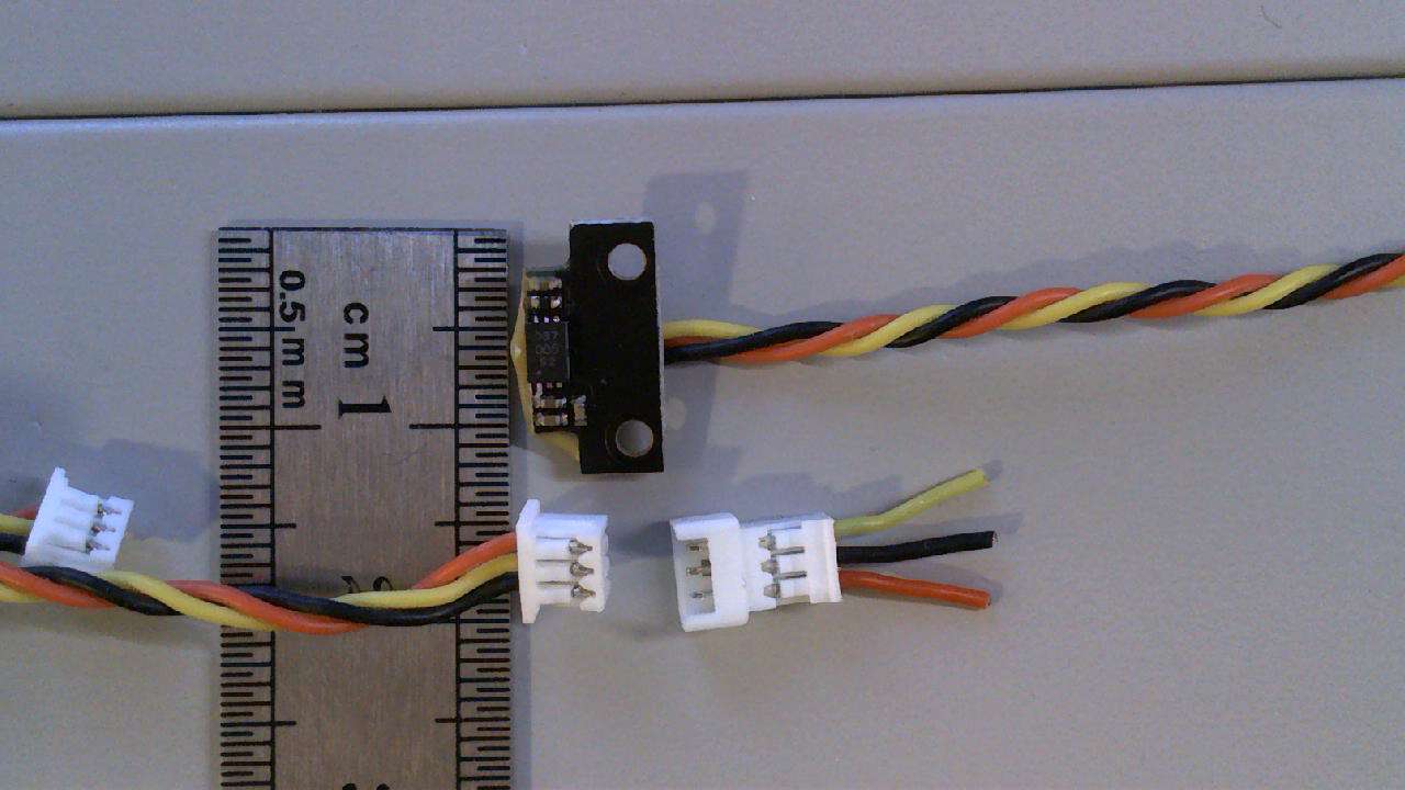 Here are the connectors used & their sizes.
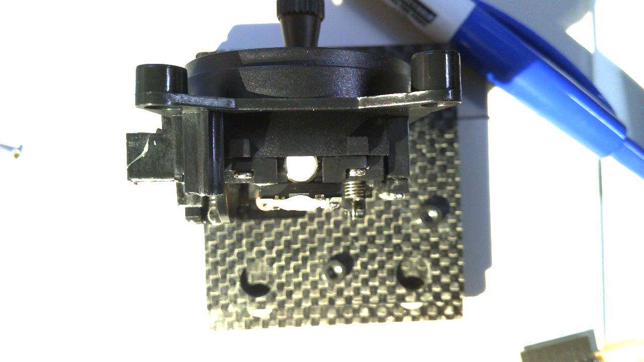 Gap between hall sensor and magnet
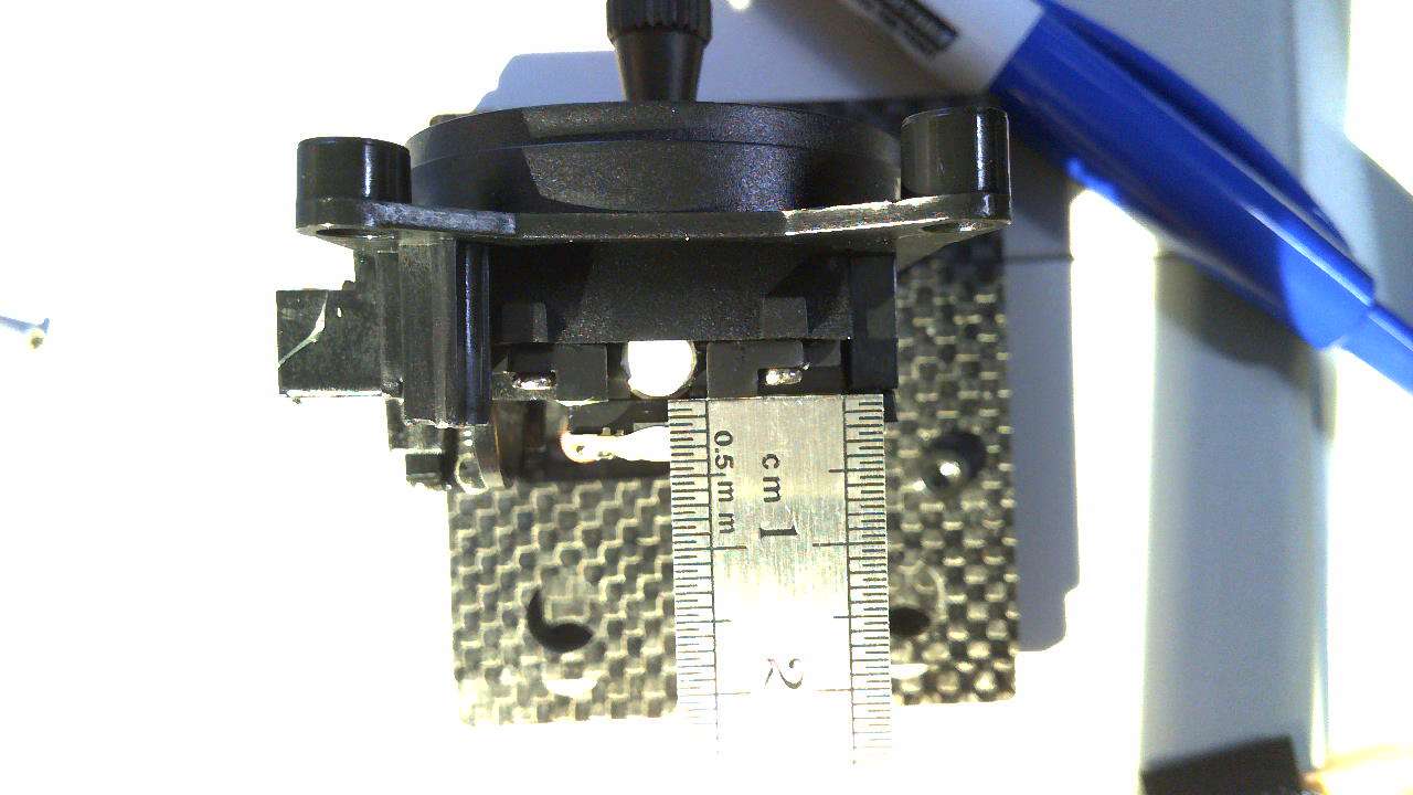 Gap measurement ~1.0mm
TI Hall Effect sensors
I found the datasheets for TI Linear Hall-effect sensors to be much easier to understand. However, the sensitivity measurements were completely different making it difficult to figure out if TI hall effect sensors could replace allegro sensors in my application.
Of most interest to me was that lots of RC folks complain about temperature drift on their hall effect gimbals. The TI DRV5055 Hall Effect Sensor datasheet says: “Compensation For Magnet Temperature Drift for A1/A2/A3/A4 Versions and None for Z1/Z2/Z3/Z4 Versions” The A version seem like they may solve this issue!
Best Hall Sensors Radio Control Gimbals
- Texas Instruments DRV5055-Q1 can run at 3.3 or 5VDC (device features magnet temperature compensation to counteract how magnets drift for linear performance across a wide – 40°C to +150°C temperature range)
- Texas Instruments DRV5055A3 can run at 3.3 or 5VDC (features magnet temperature compensation to counteract how magnets drift for linear performance across a wide – 40°C to 125°C temperature range)
- Allegro A1388 sensor takes 4.5 to 5.50 v in and outputs analog of 0 - 5vdc (or slightly narrower)
Note: That Allegro & Texas Instruments define the sensitivity of their hall sensors with different values. However there is an easy base 10 conversion to translate: How can I measure my exposure to magnetic fields from electrical sources? “The strength of the magnetic field is expressed in units of Tesla (T) or microtesla (µT). Another unit, which is commonly used is the Gauss (G) or milligauss (mG), where 1 G is equivalent to 10-4 T (or 1 mG = 0.1µT).”
- TI A3 series sensitivity: 25 mV/mT
- Allegro A1388 LLHLX-2-T series sensitivity: 2.5 mV/G = 25 mV/mT
Older 3VD RC transmitters
I would like to convert my of old work out potentiometer gimbals on our Turnigy 9x transmitters to Hall Effect sensor based gimbals. However the 9x runs on 5vdc. We are in luck because there are two good 3.3VDC hall sensor options above.
A nice guide that explains how a hall effect gimbal would work on a 9x radio is Conversion of a Turnigy 9X to Hall effect sensors
Connectors
The connectors on all my radio control gimbals are all 1.25mm pitch 1x3 position. These are Molex picoblade connectors and I purchased surface mount headers for my custom board from DigiKey.
The connector pinout is standardized, but be aware the wire colors used may not be the same on all gimbals. Most gimbals are setup Red - Yellow signal and Black +. As you can see the colors may not match standards.
Board design
 Above: Rev 1 KiCad Schematic in SVG format, right click and open in new tab to zoom in closer!
3D View
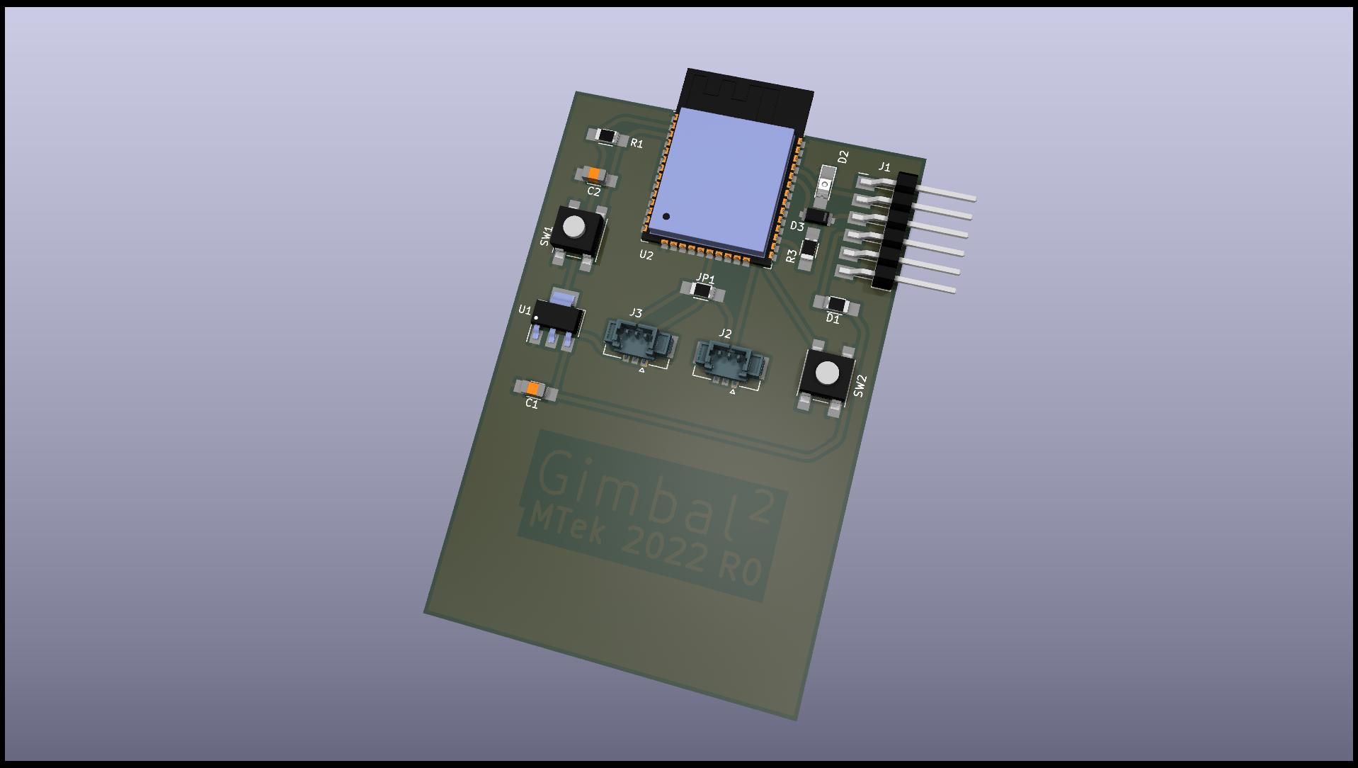
Above: Rev 1 KiCad 3D Board view. The board is double sided with the back side being ground. Note the two holes for Rivet vias.
Rivet Vias
I realized I was spending more time trying to route traces then it would take to learn how to use vias and a double sided board with ground on the backside. So I searched the Fab Academy Repo and found this great page: PCB_Rivets
The company Bungard makes the rivets we sue in Fab Academy and the data for them is quite simple and located at: Through-hole rivets. This site says “a drilling diameter that is 0.1mm larger than the outer diameter is required.” So i used the online Tables Generator to make a quick markdown table of the two sizes of rivets on the Fab Inventory, including drill diameters (⌀):
| ID | OD +/- 0.03 mm | Drill ⌀ | Shaft L +/- 0.10 mm | Head ⌀ +/- 0.15mm | wall d +/- 10% |
|---|---|---|---|---|---|
| 0.6mm | 0.8mm | 0.9mm | 2.2mm | 1.3mm | 0.1mm |
| 1.0mm | 1.4mm | 1.5mm | 2.5mm | 2.2mm | 0.2mm |
In the USA you can buy Favorit Rivets from VPCinc.com The size I used was the 1.0mm Inner diameter. Lets see how much each Rivet costs:
| Order Code | Description | Price per 1k | Price Each |
|---|---|---|---|
| 700-028-2 | Favorit RIVETS 1.0mm ID | $52.50 | 0.525¢ |
I’m using 3 vias, so total cost is $1.58
BOM
| Index | Item | QTY | Supplier | Mfg P/N | Cost Ea | Ext Cost | Link | Note |
|---|---|---|---|---|---|---|---|---|
| 1 | CAP CER 10UF 35V X6S 1206 | 2 | Digikey | GRT31CC8YA106ME01L | 0.47 | $0.94 | https://www.digikey.com/en/products/detail/murata-electronics/GRT31CC8YA106ME01L/5416847 | |
| 2 | RES 10K OHM 1% 1/4W 1206 | 1 | Digikey | RC1206FR-0710KL | 0.1 | $0.10 | https://www.digikey.com/en/products/detail/yageo/RC1206FR-0710KL/728483 | |
| 3 | RES 1K OHM 1% 1/4W 1206 | 1 | Digikey | RC1206FR-071KL | 0.1 | $0.10 | https://www.digikey.com/en/products/detail/yageo/RC1206FR-071KL/728387 | |
| 4 | DIODE SCHOTTKY 100V 150MA SOD123 | 1 | Digikey | BAT46ZFILM | 0.46 | $0.46 | https://www.digikey.com/en/products/detail/stmicroelectronics/BAT46ZFILM/1207026 | |
| 5 | LED RED CLEAR 2SMD | 1 | Digikey | XZMDK60W | 0.39 | $0.39 | https://www.digikey.com/en/products/detail/sunled/XZMDK60W/4902037 | |
| 6 | DIODE ZENER 3.3V 500MW SOD123 | 1 | Digikey | BZT52C3V3-7-F | 0.23 | $0.23 | https://www.digikey.com/en/products/detail/diodes-incorporated/BZT52C3V3-7-F/717734 | |
| 7 | IC REG LINEAR 3.3V 1A SOT223 | 1 | Digikey | ZLDO1117G33TA | 0.51 | $0.51 | https://www.digikey.com/en/products/detail/diodes-incorporated/ZLDO1117G33TA/2095592 | |
| 8 | ESP32-WROOM-32D microcontroller unit | 1 | Digikey | ESP32-WROOM-32D | 4.08 | $4.08 | https://www.digikey.com/en/products/detail/espressif-systems/ESP32-WROOM-32D-4MB/9381716 | |
| 9 | SWITCH TACTILE SPST-NO 0.05A 24V | 2 | Digikey | B3SN-3112P | 1.07 | $2.14 | https://www.digikey.com/en/products/detail/omron-electronics-inc-emc-div/B3SN-3112P/27856 | |
| 10 | RES 0 OHM JUMPER 1/4W 1206 | 1 | Digikey | RC1206FR-070RL | 0.10 | $0.10 | https://www.digikey.com/en/products/detail/yageo/RC1206FR-070RL/5698945 | |
| 11 | CONN HEADER SMD 3POS 1.25MM | 2 | Digikey | 533980371 | 0.75 | $1.50 | https://www.digikey.com/en/products/detail/molex/0533980371/699067 | |
| 12 | CONN HEADER SMD R/A 36POS 2.54MM | 1 | Digikey | GBC36SGSN-M89 | 0.1175 | $0.12 | https://www.digikey.com/en/products/detail/sullins-connector-solutions/GBC36SGSN-M89/862355 | |
| 13 | CONN HEADER SMD R/A 36POS 2.54MM | 1 | Digikey | GBC36SGSN-M89 | 0.1175 | $0.12 | https://www.digikey.com/en/products/detail/sullins-connector-solutions/GBC36SGSN-M89/862355 | |
| 14 | FR1 Board 2x3 Single Sided | 1 | Carbide 3D | 2x3 SS | 1.00 | $1.00 | https://shop.carbide3d.com/products/fr1-copper-clad?variant=41237063046 | |
| 15 | Favorit RIVETS 1.0mm ID | 2 | VPC | 700-028-2 | 0.525 | $1.05 | https://www.vpcinc.com/Category/Favorit-Through-Hole-Rivets-104.cfm | |
| Total | $12.85 |
Interactive BOM
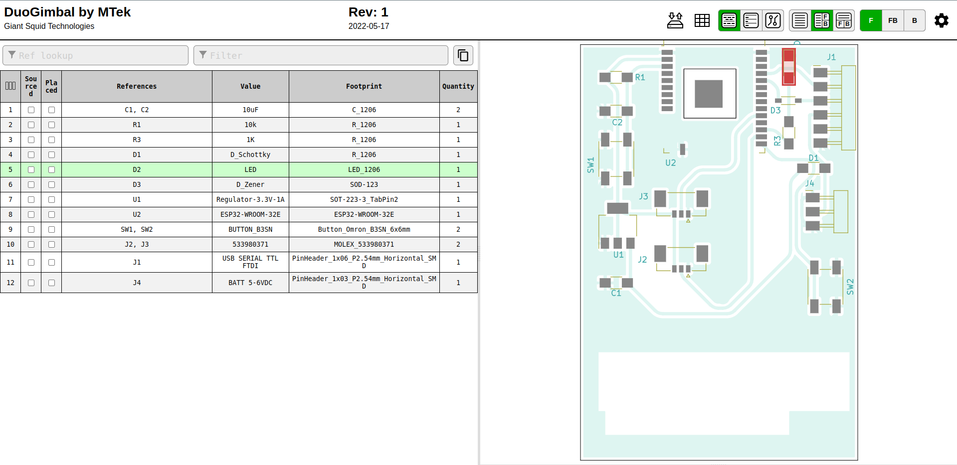
Above: Click image to access the HTML Interactive Bill of Materials (iBOM) generated by KiCad.
CAM
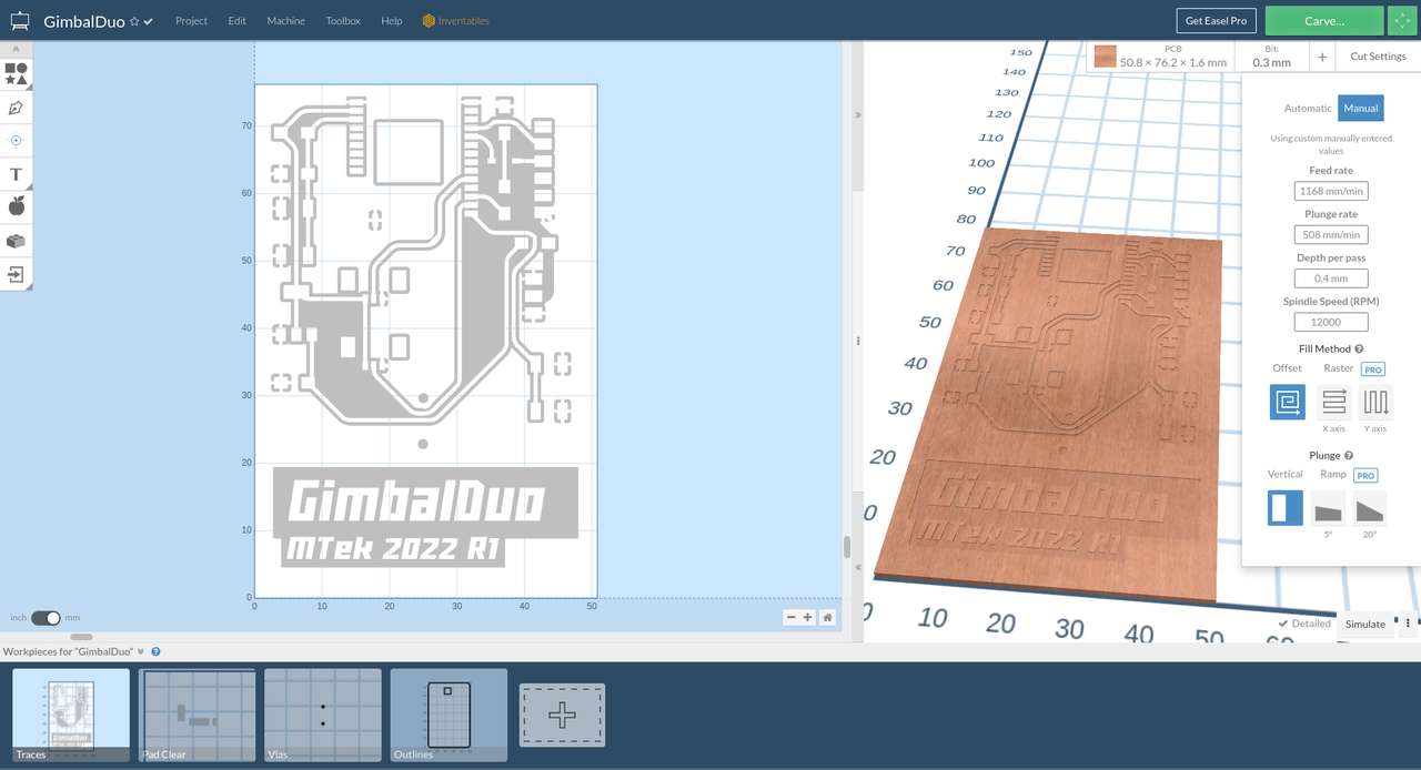 See Easel CAM parameters above.
You can access my Easel GimbalDou CAM data and with the specified tooling you could duplicate my board on a x-carve mill. With minor setup changes you can use easel to mill this board on any GRBL compatible CNC machine.
See Easel CAM parameters above.
You can access my Easel GimbalDou CAM data and with the specified tooling you could duplicate my board on a x-carve mill. With minor setup changes you can use easel to mill this board on any GRBL compatible CNC machine.
Milling
 I milled my board on the small x-carve 300 x 300 mm CNC Mill.
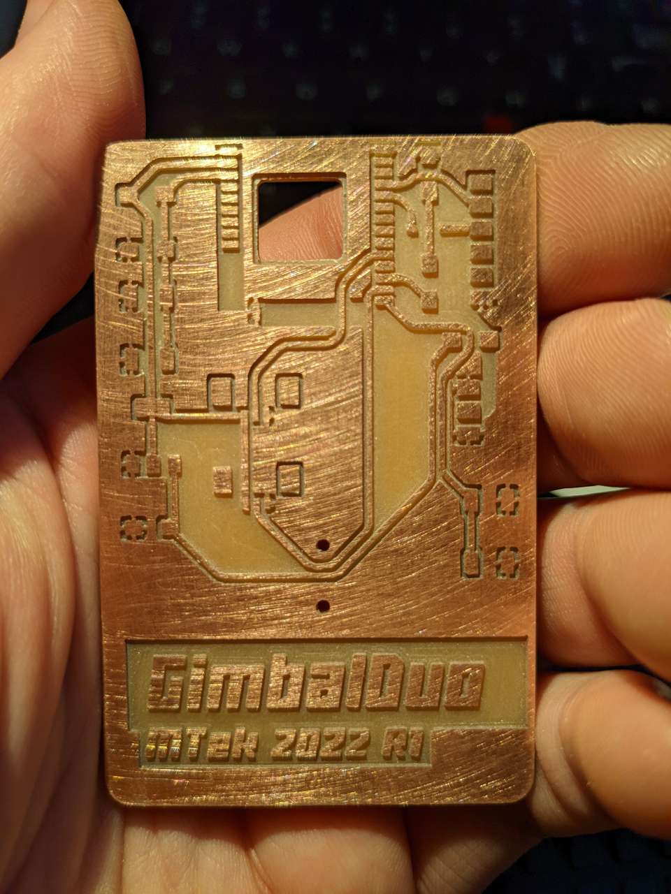
Stuffing
Stuffing isn’t just for Turkey’s!
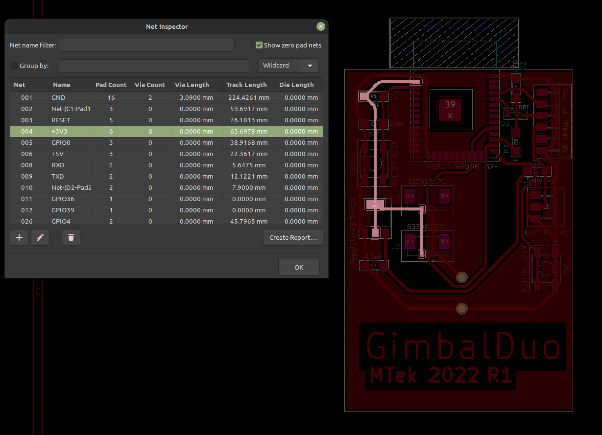
I used the interactive bom and a new tool I found in KiCad called “Net Inspector” that allows you to highlight individual nets, for trouble shooting.
programming
I used Sara and Rui Santos’ excellent guides at Random Nerd Tutorials to learn about reading analog values from the potentiometer sensor gimbals:
measure something and read it
I have used some excellent esp32 pin guides in the past, but the one at randomnerdtutorials is the best I’ve seen so far! ESP32 Pinout Reference: Which GPIO pins should you use?
ESP32 ADC – Read Analog Values with Arduino IDE
I decide it was time to try a different coding language: MicroPython.
I found this tutorial on MicroPython useful: ESP32/ESP8266 Analog Readings with MicroPython
To work with MicroPython I tried out Thonny IDE. I used the Linux Mint Software Manager to install Thonny. I tried uPyCraft as well but it was difficult to install so I stopped and moved ahead with Thonny.
I also needed to install python 3, esptool and stuptools, but when I went to my linux mint software manager both were already installed, probably from installing expresif dev software in previous assignments.
Next the guide said to run the esptool command, i typed the following into terminal:
python -m esptool
A bunch of expected text resulted showing that esptool was working:
esptool.py v4.1…
Next I plugged in my ESP32 GimbalDou board and flashed it with the MircoPython firmware:
The guide said:
If you are putting MicroPython on your board for the first time then you should first erase the entire flash using:
esptool.py --chip esp32 --port /dev/ttyUSB0 erase_flash
From then on program the firmware starting at address 0x1000:
esptool.py --chip esp32 --port /dev/ttyUSB0 --baud 460800 write_flash -z 0x1000 esp32-xxlatestrelease.bin
replace the “esp32-xxlatestrelease.bin” with the latest release .bin file downloaded on the the bottom of the page above, or use the file linked in the files section of this page. Remember that you need to reset your esp32 board to be programmed by pressing and holding the prog button and then pressing and releasing the reset button, then releasing the prog button.
during the command above the following was displayed:
esptool.py v4.1
Serial port /dev/ttyUSB0
Connecting......
Chip is ESP32-D0WD (revision 1)
Features: WiFi, BT, Dual Core, 240MHz, VRef calibration in efuse, Coding Scheme None
Crystal is 40MHz
MAC: ac:67:b2:d5:85:10
Uploading stub...
Running stub...
Stub running...
Erasing flash (this may take a while)...
Chip erase completed successfully in 16.9s
Hard resetting via RTS pin...
Next I ran the command to install the latest micropython firmware to the esp32:
esptool.py --chip esp32 --port /dev/ttyUSB0 --baud 460800 write_flash -z 0x1000 esp32-20220618-v1.19.1.bin
during the flash command above the following was displayed:
esptool.py v4.1
Serial port /dev/ttyUSB0
Connecting.....
Chip is ESP32-D0WD (revision 1)
Features: WiFi, BT, Dual Core, 240MHz, VRef calibration in efuse, Coding Scheme None
Crystal is 40MHz
MAC: ac:67:b2:d5:85:10
Uploading stub...
Running stub...
Stub running...
Changing baud rate to 460800
Changed.
Configuring flash size...
Flash will be erased from 0x00001000 to 0x0017efff...
Compressed 1560976 bytes to 1029132...
Wrote 1560976 bytes (1029132 compressed) at 0x00001000 in 25.2 seconds (effective 495.6 kbit/s)...
Hash of data verified.

Leaving...
Hard resetting via RTS pin...
Next I had to find what port my ESP32 was connected to, using the arduino ide I went to tools, port and found that my port was /dev/ttyUSB0 Not sure why this is needed, I moved onto the next task.
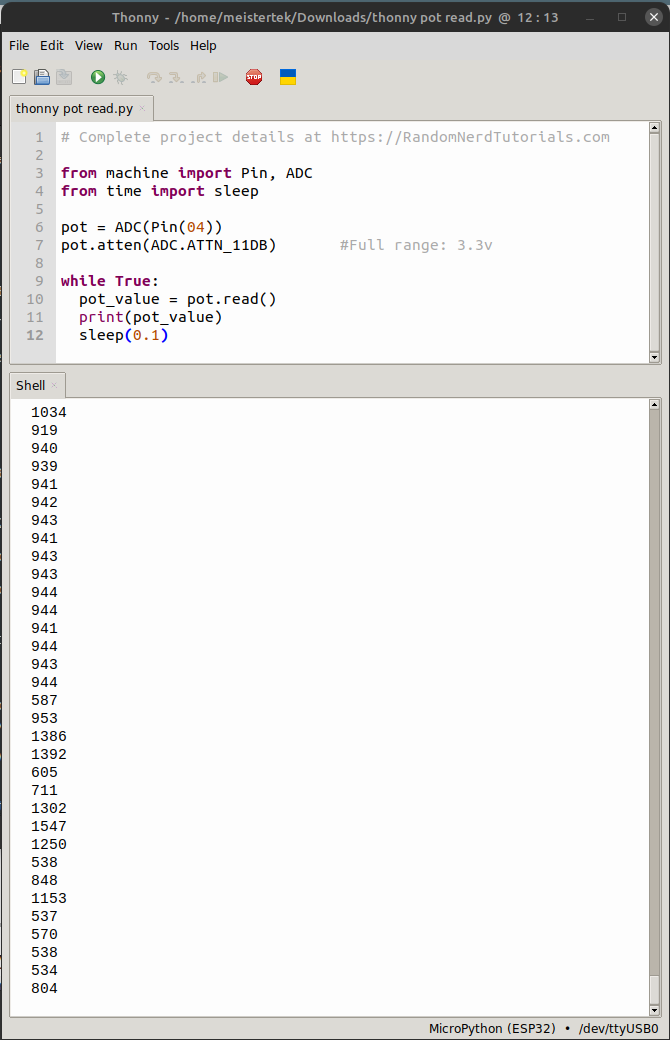
Next I ran the MicroPython script replacing the given pin with the GimbalDuo GPIO 04 which is simply pot = ADC(Pin(04)) in MicroPython.
# Complete project details at https://RandomNerdTutorials.com

from machine import Pin, ADC
from time import sleep

pot = ADC(Pin(04))
pot.atten(ADC.ATTN_11DB)       #Full range: 3.3v

while True:
  pot_value = pot.read()
  print(pot_value)
  sleep(0.1)
I cut and pasted the code into Thonny IDE. Next in Thonny I selected “Run” “select interpreter” and then selected: “MicroPython (ESP32)”” and Port: “”…()/dev/ttyUSB0)…”” hmm that’s why they wanted me to get the port above!
Next I pressed the reset button on the GimbalDou board while it was plugged into the usb port. This triggered the Shell window to respond with confirmation:
rst:0x1 (POWERON_RESET),boot:0x12 (SPI_FAST_FLASH_BOOT)
configsip: 0, SPIWP:0xee
clk_drv:0x00,q_drv:0x00,d_drv:0x00,cs0_drv:0x00,hd_drv:0x00,wp_drv:0x00
mode:DIO, clock div:2
load:0x3fff0030,len:4540
ho 0 tail 12 room 4
load:0x40078000,len:12344
ho 0 tail 12 room 4
load:0x40080400,len:4124
entry 0x40080680
MicroPython v1.19.1 on 2022-06-18; ESP32 module with ESP32
Type "help()" for more information.
Next I clicked the play button and got:
>>> %Run -c $EDITOR_CONTENT
0
274
283
281
288
286
281
282
279
282
288
286
288
286
283
286
284
283
285
284
285
287
285
286
286
288
283
285
286
287
284
285
277
Troubleshooting
something was wrong :( maybe my pot wires were messed up? I tried the run the program again, but this time I touched the circuit board traces near the pot. This would introduce my finger as a variable resistor or potentiometer to the circuit and the following was displayed:
>>> %Run -c $EDITOR_CONTENT
372
426
2254
3617
3338
2286
1872
1787
1750
1746
1804
1755
1719
1710
1696
1680
1682
1707
1847
2357
2873
1939
1648
1788
1714
1703
1655
1648
1677
1677
1607
1597
1567
1652
1713
1811
1839
1680
0
1109
395
289
283
284
279
281
282
283
288
278
276
279
279
279
282
282
279
285
282
285
285
282

────────────────────────────────────────────────────────────────────────────────────────────────────────────────────────────────────────────────────────────────────────────────────────────────────────
MicroPython v1.19.1 on 2022-06-18; ESP32 module with ESP32
Type "help()" for more information.
>>>
Cool! the new numbers above corresponded to a light and heavy touch of the traces with my fingers. Next I changed the wiring on my pots.
Then I ran the code again moving the gimbal. This time I got nothing but zeros. I checked the board for shorts and found one going from signal to ground. I de-soldered the connector for the gimbal (potentiometer) and found that a ground pour was shorting to the signal contact of the connector. I removed the section of ground pour that was causing the short and then re-soldered the connector and ran the MicroPython code again…
And got this via the Thonny IDE Shell while moving the gimbal:
2206
2207
2205
2203
2208
2203
1636
1275
1412
2220
2739
3955
4041
3029
2346
1388
528
529
944
2893
4095
4095
3711
2777
1695
927
526
523
511
509
510
525
524
528
528
528
528
516
510
530
527
522
519
507
517
526
1162
2652
4095
4095
4095
4095
4095
4095
4095
4095
4095
4095
4095
4095
4095
4095
4095
4095
4095
4095
4095
3745
2703
1649
688
518
506
499
499
499
496
496
496
496
496
496
496
496
496
496
496
496
496
509
1035
2295
3264
4095
4095
4095
4095
4095
4095
4095
4095
3723
2367
1157
505
505
505
503
501
499
499
497
497
539
1728
3439
4095
4095
2205
2206
2207
2207
2204
2208
2206
2206
2206
2208
2208
2207
2208
2203
2206
2206
Holy Frack! it works! Time to take a video
Hero Video
Above: Video of Thonny IDE MicroPython code for potentiometer gimbal input showing changing values with 11db of signal Attenuation via Thonny Shell
 Above: View of Thonny IDE in use running the MicroPython code below.
code
MicroPython Code “esp32ReadAnalog.py” with comments explaining my understanding of the code.
# Complete project details at https://RandomNerdTutorials.com
# modified by Dan "MTek" Meyer 2022-Jul-31 Sun 9:44pm

from machine import Pin, ADC   #ADC=analog digital conversion
from time import sleep

pot = ADC(Pin(04))             #pick your boards GPIO pin
pot.atten(ADC.ATTN_11DB)       #Full range: 3.3v with x db signal attenuation

while True:                    #while loop forever?
  pot_value = pot.read()       #read the pot value
  print(pot_value)             #print pot value to shell
  sleep(0.1)                   #pause x.x seconds between reads
Notes for future projects
Single stick RC aircraft control
I have always wanted to design and make a single stick RC aircraft control, well it looks like this is quite possible for me to do. Single stick RC controls date back to 60’s and 70’s. A single stick gimbal adds a twist knob on the end of the stick for rudder control.
It turns out our friends in the RC construction vehicles finally drove radio control manufactures to re-visit the single stick control. This link shows a tear down of the brand new gimbal extender that fits on the end of traditional gimbal sticks! FrSky 3-Axis CNC Gimbal Extender with Magnetic Hall Effect Sensor for MC12 Gimbal post #27 shows mechanical disassembly and post #31 shows a close up of the hall sensor.