Computer-Controlled Machining
1. Week Assignments
group assignment
- do your lab's safety training
- test runout, alignment, fixturing, speeds, feeds, materials, and toolpaths for your machine
individual assignment
- make (design+mill+assemble) something big (~meter-scale)
- extra credit: don't use fasteners or glue
- extra credit: include curved surfaces
- extra credit: use three-axis toolpaths
2. Prior Knowledge
I have not used a ShopBot or any CNC milling machine before.
3. Work!
Documentation of some Waag heroes I used for reference:
3.1. Group Assignment
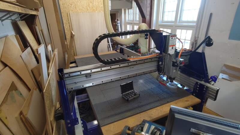
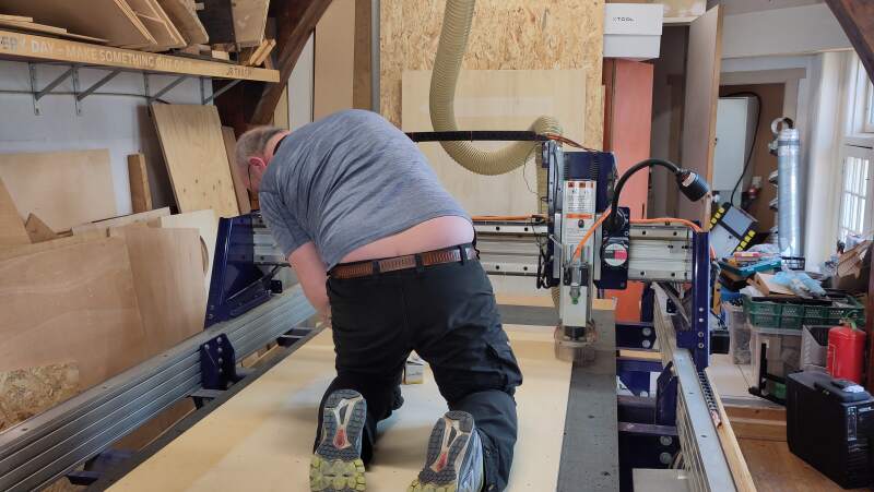
We started with safety and machine instructions. Henk showed us around the ShopBot and its dust collection installation.
Some facts about the ShopBot at the Waag:
- It has 2.5 dimensions (no tilting).
- X size is 2.5 meters.
- Y size is 1.3 meters.
- Z size is 20 centimeters.
- Spindle maximum speed is 18,000 rpm.
- We'll only be using a 5mm, 2-flute, uncoated, flat-end milling bit for this week.
The machine has a large QR-code on the side pointing to Waag/Fablab Amsterdam - How to use the ShopBot]], which describes how to operate the machine very well. However, there are a couple of important things missing:
- Always remove the milling bit first for inspection. There should not be any broken-off parts, it should be the bit you expect, and it should be fastened properly after inspection.
- Clean the inside of the collet after removing the milling bit.
- Check that nothing is leaning against the machine or on the bed before starting it.
In case of fire: turn the dust collector off and detach the bag (see figure 2). If there's smoke coming from the collection bag: open the window and throw the bag out the window. If there is still fire, use the fire extinguisher to put it out.
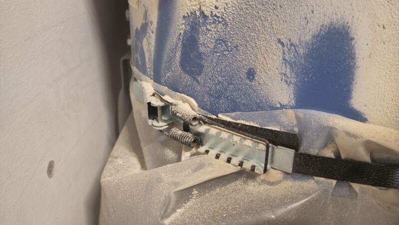
Figure 2: Clamp holding the dust bag - Keep the door of the dust collector open; otherwise, the fire alarm may give a false alarm.
- The X/Y axes are not what you expect. The X-axis goes from front to back and the Y-axis from left to right. Fortunately, the arrow keys on the keyboard when running the keypad in ShopBot console point in the right direction.
As an example Henk setup a job in VCarve Pro (version 8) on the computer attached to the ShopBot while we watched and took notes. There is also a nice VCarve tutorial which can be found on the site at the QR-code to supplement notes taken.
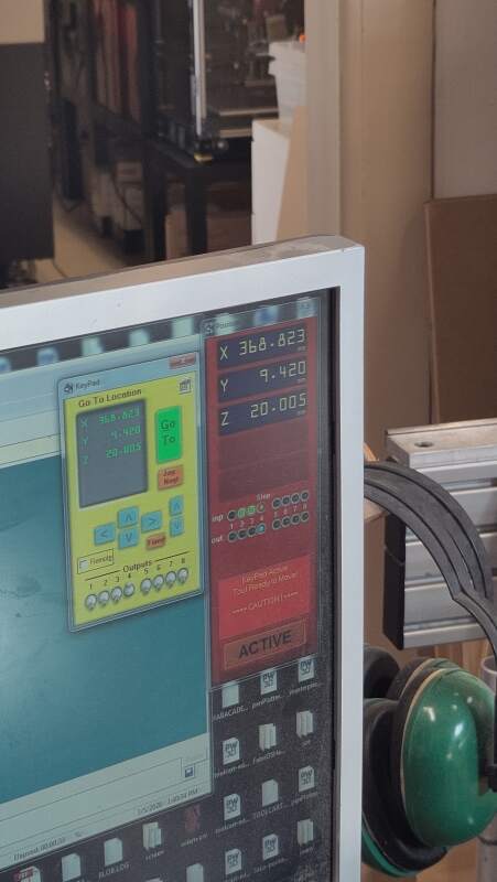
After detaching the milling bit for inspection and cleaning the collet. We cleaned the bed and placed a piece of plywood on it. Then, we positioned the milling bit at the bottom-right corner of the material by stepping to it using the "K" function in ShopBot Console. When it was positioned correctly, we used the Zero -> Zero X and Y axes tool to set the starting point and took a photo for when we need to restart the machine or computer for some reason, like a computer crash, hitting the Stop button etc.
Henk showed us how to create some sample vectors in VCarve Pro and some profiles (all through, so depth set to the material thickness) and matching pockets toolpaths (half the material thickness). For all cuts cutting direction "climbing" was selected and for the pockets we had "offset" and "raster" clearing methods. For one of the pockets we used a higher feed rate of 80 mm/s than the default 60 mm/s (adjustable through Tool selection). For the profiles, tabs were applied to avoid parts coming loose during milling, and T- and dog- bone fillets to clear the corners (you can not make a sharp corner with a round bit).
Before running the tests, the material needed to be screwed down to the sacrificial layer to make it a flat as possible (wood tends to warp) and avoid it from moving around. For this shallow drill holes were added to the job in VCarve and exported separately as an SPB-file to mark the places where the screws came. It is very important to not run this job again after the screws are in!
At first, we (mistakenly) set used the ShopBot console to Z-zero on top of the material. However, the job in VCarve was set to have the Z-zero on the bottom of the material. This resulted in a rather boring airshow. Fortunately, it was not the other way around.
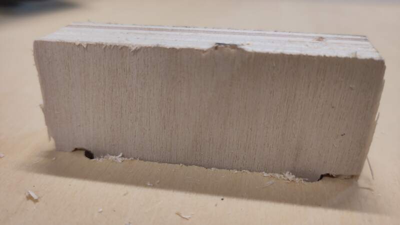
After 10 minutes of milling, this is the result.
We repeated the run with some extra cuts on a board of OSB (Oriented Strand Board).
3.1.1. Test results
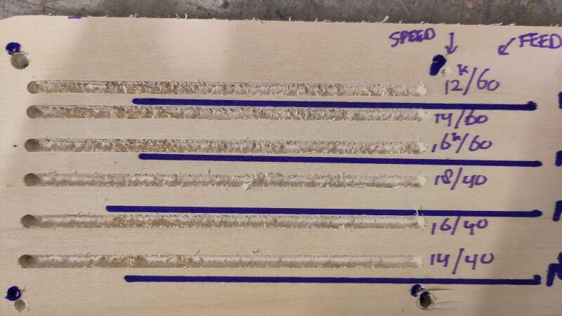
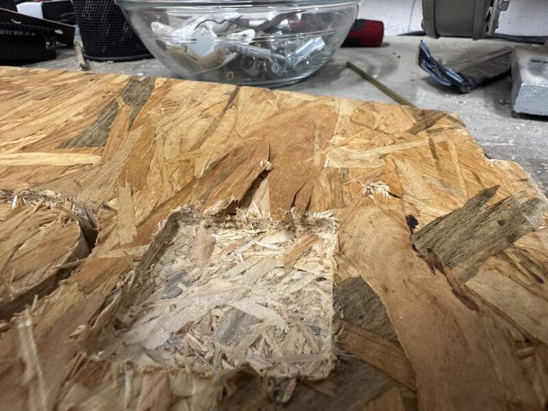
Using a feed rate of 80mm/s being a bit messier than the default 60mm/s. Comparing the plywood with the OSB, there was a much bigger difference in fraying (see figure 9). We could conclude this feed rate difference matters less than what the wood used. Even in a single slab of plywood, cuts in the same direction can be frayed on one part of the board and be fine on another.
A second test to include the spindle speed did not really reveal any sweet spot for that particular piece of wood. Although, I this case I would use 14k rpm and a feed rate of 40 mm/s.
Apart from the fraying OSB the results we pretty similar between the OSB and the plywood. But, milling the OSB was a lot louder, probably because it contains more glue.
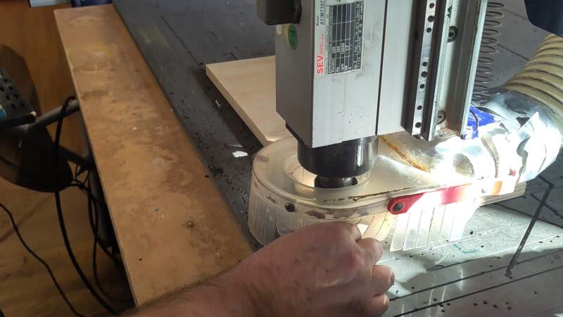
After the speed tests we ran a runout test by projecting the shadow of the rotating bit on a piece of paper filming that.
At 1k rpm it is a bit wobbly.
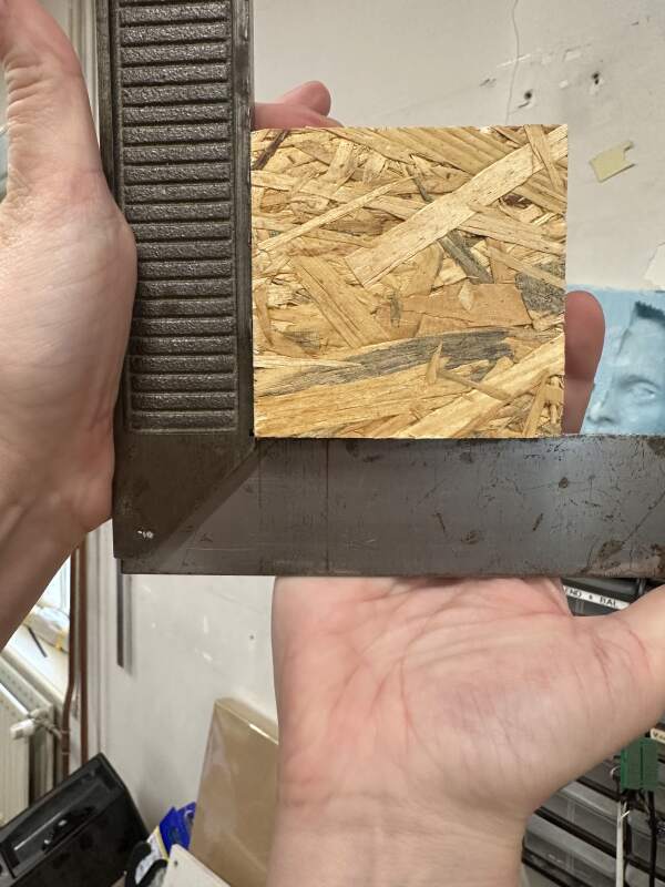
The alignment between the X and Y-axis seem pretty good (see figure 10).
3.1.2. Steps to run a job
Take the following steps when using the ShopBot:
- Turn on the computer.
- Turn on the ShopBot.
- Remove the milling bit for inspection. See also: changing the milling bit.
- Clean the collet.
- Install the milling bit.
- Clean the sacrificial layer and remove any unevenness.
- Find and use the least damaged part of the sacrificial layer, which will be covered by the material, to do Z-leveling. See also: Zeroing the axes.
- Place the material on the bed.
- Open a new job in VCarve and enter the material dimensions. See also: Job setup.
- If the material is large enough to stay in place during dilling, create a drill path in VCarve for screwing down the material onto the sacrificial layer. Keep them a few centimeters away from the paths you will be cutting and make them a couple of millimeters deep. See also: Drilling toolpath.
- Check that nothing is left on the bed or leaning agains the machine.
- Zero the machine to the bottom-right edged of the material using XY in ShopBot Console toolbar. See also step about Z-leveling.
- Take a photo of the X and Y coordinates.
- Start the dust collector.
- Start the spindle. See also Starting the job.
- Select the drilling job as exported from VCarve.
- Run the job.
- Turn off the spindle and move the head away from the material.
- Screw down the material in the drilled holes.
- Start the spindle and run the job.
- Done? Stop the machine and vacuum, remove work from the bed, and clean up the mess!
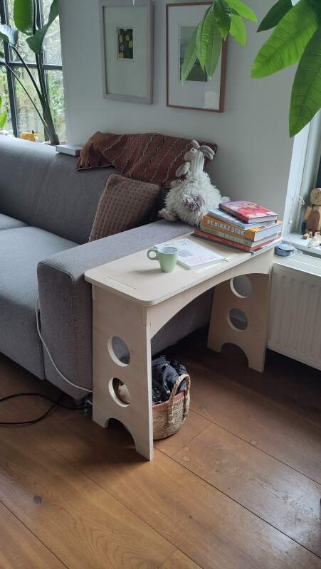
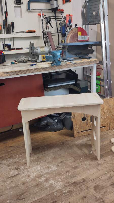
3.2. Something big
I wanted to make a table to put my coffee on when I sit on the sofa, but I did not immediately decide next to which sofa it should go. So, I made it fully parametric: not only material thickness and but all dimensions.
table_height = 610;
table_width = 300;
table_depth = 780;

bit_diameter = 5;
thickness = 18;
thickness_offset = thickness * 1.5;

side_height = table_height * .25;
side_cut = 5.5;

$fn = 200;

module rounded_square(w, d, r) {
  translate([r, r, 0]) circle(r);
  translate([w - r, r, 0]) circle(r);
  translate([r, d - r, 0]) circle(r);
  translate([w - r, d - r, 0]) circle(r);
  translate([r, 0, 0]) square([w - r * 2, d]);
  translate([0, r, 0]) square([w, d - r * 2]);
}

module slot_mask(coordinates, bits = [true, true, true, true]) {
  r = bit_diameter * .75; // leave some room to turn
  square(coordinates);
  if (bits[0]) {
    translate([r / 2, r / 2, 0]) circle(r);
  }
  if (bits[1]) {
    translate([coordinates[0] - r / 2, r / 2, 0]) circle(r);
  }
  if (bits[2]) {
    translate([coordinates[0] - r / 2, coordinates[1] - r / 2, 0]) circle(r);
  }
  if (bits[3]) {
    translate([r / 2, coordinates[1] - r / 2, 0]) circle(r);
  }
}

module table_top() {
  difference() {
    rounded_square(table_width, table_depth, thickness * 2);

    // head slots
    hs = table_width / 2 - table_head_slot / 2;
    translate([hs, thickness_offset, 0])
      slot_mask([table_head_slot, thickness]);
    translate([hs, table_depth - (thickness_offset + thickness), 0])
      slot_mask([table_head_slot, thickness]);

    // side slots
    ss = table_depth / 2 - table_side_top_slot / 2;
    translate([thickness_offset, ss, 0])
      slot_mask([thickness, table_side_top_slot]);
    translate([table_width - thickness_offset - thickness, ss, 0])
      slot_mask([thickness, table_side_top_slot]);
  }
}

table_head_width = table_width - thickness_offset * 2;
table_head_slot = table_head_width / 2;

module table_head() {
  translate([thickness_offset, 0, 0]) difference() {
    union() {
      square([table_head_width, table_height - thickness]);
      polygon([[-thickness_offset, 0],
               [0, table_height - thickness - table_side_slot],
               [table_head_width, table_height - thickness - table_side_slot],
               [table_head_width + thickness_offset, 0]]);
      translate([table_head_width / 4, table_height - thickness, 0])
        square([table_head_slot, thickness]);
    }

    // top slots
    ts = table_head_width / 4;
    translate([0, table_height - thickness, 0])
      slot_mask([ts, thickness], [false, true, false, false]);
    translate([table_head_width - ts, table_height - thickness, 0])
      slot_mask([ts, thickness], [true, false, false, false]);

    // side slots
    ss = table_height - thickness - table_side_slot_offset - table_side_slot;
    translate([0, ss, 0])
      slot_mask([thickness, table_side_slot], [false, true, false, false]);
    translate([table_head_width - thickness, ss, 0])
      slot_mask([thickness, table_side_slot], [true, false, false, false]);

    // feet
    rr = table_head_width / 3;
    translate([table_head_width / 2, 0, 0]) circle(rr);

    // side
    n = floor((table_height - thickness) / (rr * 2.5) - .5);
    for (i = [1:n]) {
      translate([table_head_width / 2, rr * ((i * 2) + 0.5), 0])
        circle(rr * .66);
    }
  }
}

table_side_width = table_depth - (thickness_offset) * 2;
table_side_top_slot = table_side_width / 3;
table_side_slot = side_height * .5;
table_side_slot_offset = 0;

module table_side() {
  union() {
    h = side_height;
    w = table_side_width;
    difference() {
      square([h, w]);
      translate([h * (side_cut + 0.5), w / 2, 0]) circle(h * side_cut);

      // top slot
      ts = table_side_width - table_side_top_slot * 2;
      translate([0, 0, 0])
        slot_mask([thickness, ts], [false, false, true, false]);
      translate([0, table_side_width - table_side_top_slot, 0])
        slot_mask([thickness, ts], [false, true, false, false]);

      // side slots
      translate([table_side_slot + thickness, 0, 0])
        slot_mask([table_side_slot, thickness], [false, false, false, true]);
      translate([table_side_slot + thickness, w - thickness, 0])
        slot_mask([table_side_slot, thickness], [true, false, false, false]);
    }
  }
}

module preview() {
  color("#f00")
    translate([0, 0, table_height - thickness])
    linear_extrude(thickness)
    table_top();

  color("#ff0")
    translate([0, thickness_offset + thickness, 0])
    rotate([90, 0, 0])
    linear_extrude(thickness)
    table_head();

  color("#f0f")
    translate([0, table_depth - thickness_offset, 0])
    rotate([90, 0, 0])
    linear_extrude(thickness)
    table_head();

  color("#0f0")
    translate([thickness_offset, thickness_offset, table_height])
    rotate([0, 90, 0])
    linear_extrude(thickness)
    table_side();

  color("#00f")
    translate([table_width - thickness - thickness_offset,
               thickness_offset,
               table_height])
    rotate([0, 90, 0])
    linear_extrude(thickness)
    table_side();
}

%preview();

table_top();
translate([table_width + thickness_offset, 0, 0]) table_head();
translate([table_width + thickness_offset, table_height + thickness_offset, 0]) table_head();
translate([(table_width) * 2 + thickness_offset * 2, 0, 0]) table_side();
translate([(table_width) * 2 + side_height + thickness_offset * 2 + thickness, 0, 0]) table_side();
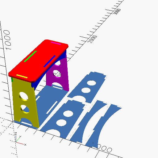
Features in the above model:
- parameteric material thickness (duh!)
- parameteric width, depth, height
- "automatic" weight saving holes in the sides
- includes "dog bone" fillets
I am very happy with the addition of dog bones in this model because it allowed me to inspect my design in the OpenSCAD viewer. The holes make it possible to see the pieces actually touch instead of being merged together.
3.2.1. Clearance test
Before milling the project, I wanted to do some press-fit tests. I used the model below to make profile toolpaths with different Clearance offset values.
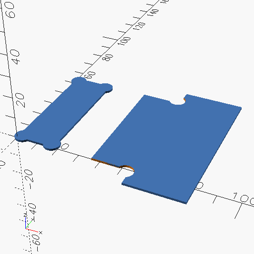
Former student Paola Zanchetta documented her work on doing a clearance test in her week 7 documentation. I started by trying her values.
3.2.2. Importing into VCarve
VCarve Pro can import PDF-files (not SVG). OpenSCAD allows exporting to PDF, but it only exports to paper sizes like A4, so it will not work for "something big". Fortunately, exporting to SVG, opening it in Inkscape and exporting there to PDF does produce a PDF with the correct dimensions.

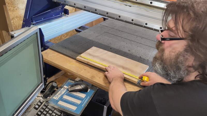
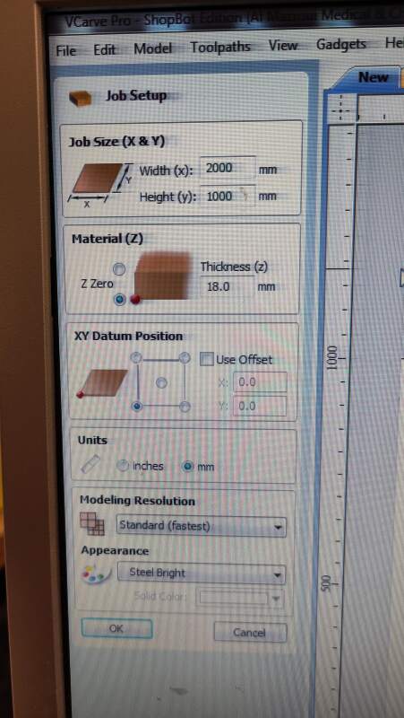
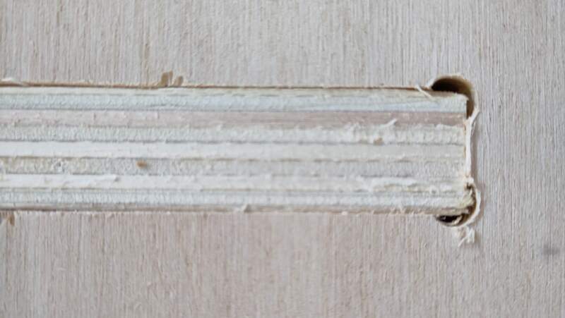
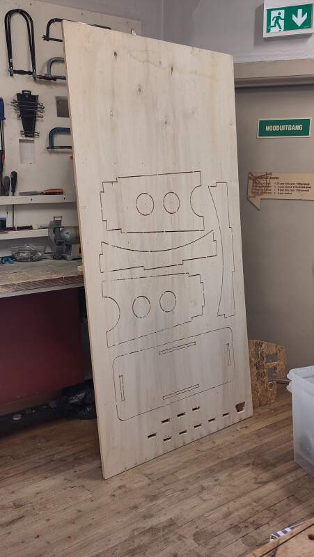
Before creating a new job in VCarve, I measured the piece of plywood I was going to use: 2000mm by 1000mm and 18mm (varying between 17.9 and 18.1) thick (see figure 13). For the zero position on the Z-axis, I selected the bottom of the material.
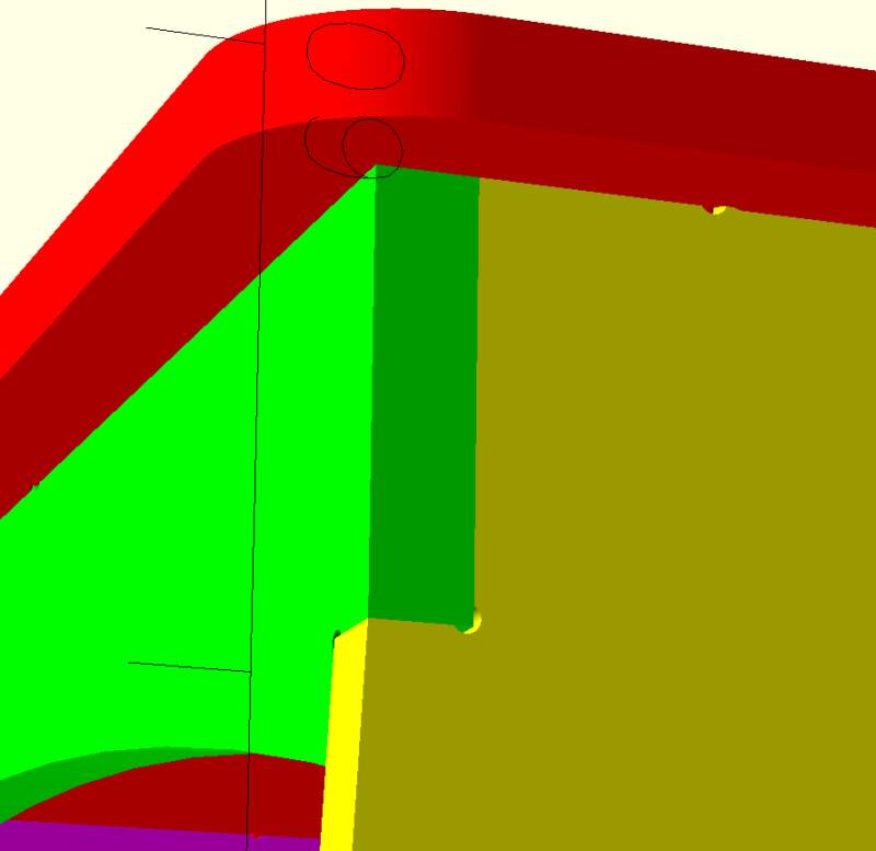
Next, I imported the clearance test and table PDFs I created. While importing I noticed the dog bones fillets VCarve creates are much wider than the bit diameter (see figure 14). I corrected my design to make the holes a bit bigger (because maybe I am too optimistic?), and re-imported them.
I had a bit of a struggle defining toolpaths and creating SPB-files. The icons in the toolbars are a bit confusing so it felt like feeling my way through the dark, but after a while, I got the hang of it.
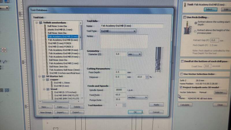
I started with drill holes (5mm circles), which I placed around the clearance test shapes. For the toolpath I selected drilling using the already selected "Fab Academy End Mill (5mm)" option and make sure it was what I expected it to be (see figure 15).
3.2.3. Milling
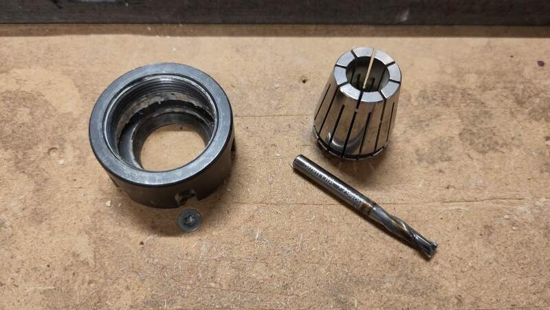
Ready to mill! I removed the milling bit (a 5mm, 2-flute, uncoated, flat-end) to inspect it (see figure 16), reattached it, cleared the bed, z-zeroed on a good part of the bed, put the plywood on it (eye-ing the alignment with the bed), x-y-zeroed the bit on the bottom-right corner of the material, turned on the vacuum, started the spindle, loaded the drilling job into ShopBot Console, and ran it.
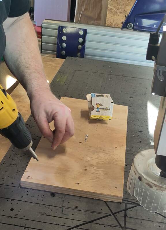
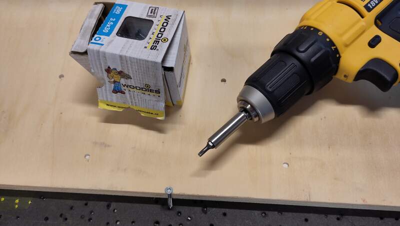
All went as expected. After the machine was done, I moved the head to the back (along the X-axis) to make some room to screw the board down using "woodies" (see figure 17).
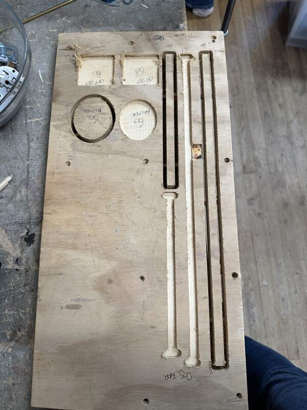
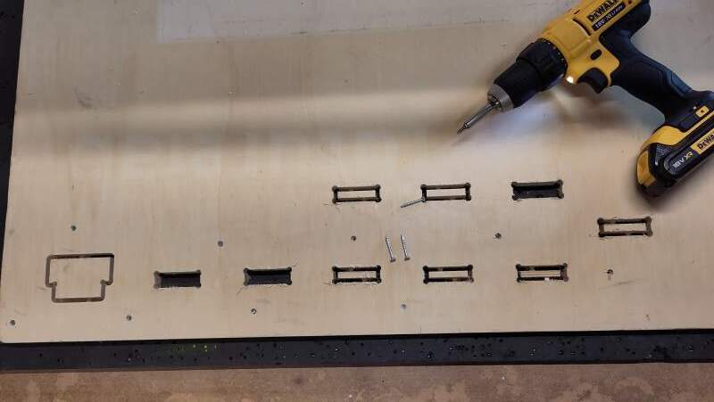
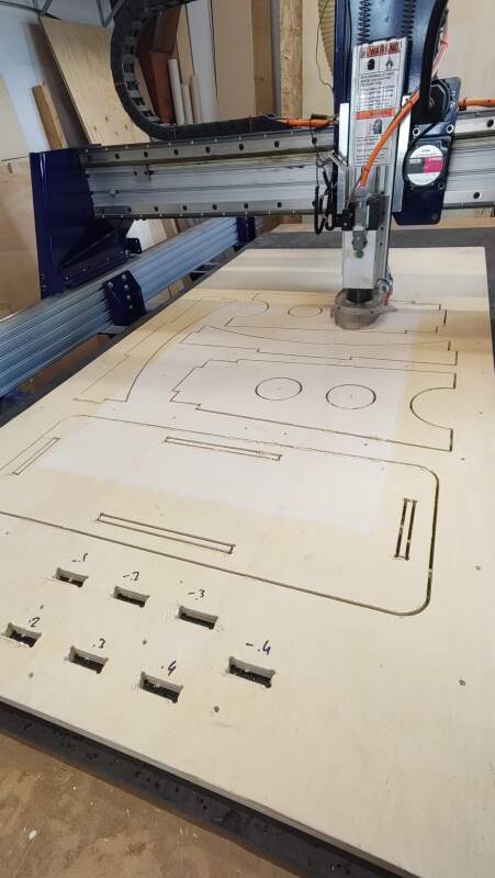
Then, once it was screwed down, I copied the slot part of the test four times and gave them clearance offsets: 0, 0.1mm, 0.2mm, and 0.3mm. Satisfied, I started this job, but after a couple of passes on the first element of the test, I realized I forgot to add tabs. Afraid I would be catapulted to death by a loose piece of the wood, I stopped the job, adjusted the toolpaths to include tabs.
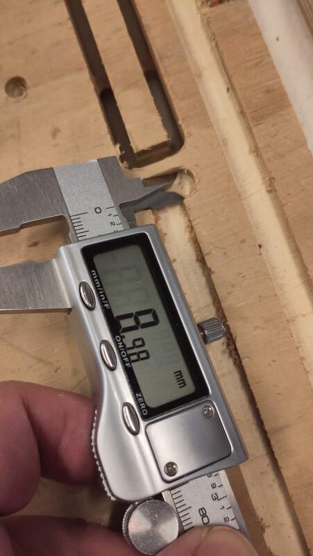
While it was cutting the last slot, I used calipers to measure the slot width; it was too narrow… I should have used negative offsets. And the skirt came loose (tighten that wing nut!).
I added new slots with negative offsets and ran it again.
After unscrewing the board and popping out the spoils, I tested the fit. Clearance offset -0.3mm gave the perfect fit (see figure 19).
Next, I reinstalled the plywood on the bed (without screws!). I prepared a lot of drill holes around the table shapes, ran the job, and screwed the board down again (using only the new holes!).
After 37 minutes of loud milling (and Così fan tutte on noise-cancelling headphones), it was done. I was at the Waag at 8:00, the job finished at 12:00. Henk was not kidding when he said it would take at least half a day with the CNC!
It is at home now and fits perfectly. I am still planning on sanding and oiling (or painting) it. I consulted my son about oiling but he advised against it because, in his opinion, the wood quality is not good enough to warrant the extra effort of doing a proper sanding job first.. I'll probably finish it after fabacademy.
4. Reflection
I was dreading this week because I had no idea what to make, and Fab Academy is taking its toll. The latter means I am tired (and the sawdust doesn't help) thus I am very wary of dangerous machines.
4.1. Good
4.2. Bad
5. Source Files
Here are my source files:
Clearance tests:
- clearance.scad (OpenSCAD code)
- clearance.pdf (final drawing to import)
Table:
- table.scad (OpenSCAD code)
- table.pdf (final drawing to import)
- table.crv (toolpaths in VCarve)
- table.sbp (G/M-code for ShopBot)
