2FAC – Two Factor Alarm Clock
Description
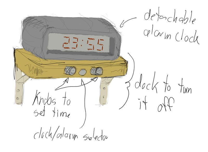
A wireless and sturdy alarm clock that can be snoozed by putting your hand on top of it, but can be not turned off unless it is placed on its (bolted down?) docking station elsewhere in the house. The docking station also allows setting the clock and alarm time using a selector button/slide for the clock or alarm, and a rotating knobs for hours and minutes. The alarm clock itself only shows the current time. The time is automatically set from the DCF77 atom clock time signal 1].
Origin
A standard alarm clock doesn't work for all teenagers who need to get up early, nor for dads (like me) who want to be able to sleep in late.
Progress
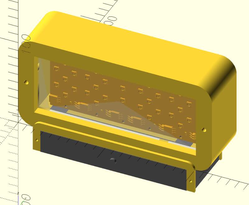
Week 2 — CAD
This week, I played with 7-segment displays and designed the shape for the clock and base station. I did not deviate much from my initial sketch because the pressure to learn FreeCAD and Blender left no room for further creativity.
Week 6 — Electronics Design
This week, I learned about Charlieplexing. If I use 7-segment digits on the clock, it will need it to drive many LEDs (4 times 7 per digit and plus 2 for the dots). I am still undecided on whether to use OLED or super fancy e-ink instead.
Week 7 — Computer Controller Machining
Wood is very pretty and a good candidate for the base station or clock, or both.
Week 8 — Electronics Production
This week, I made a working 7-segment LED digit. I am still not sure if I am going this route but it is very cool!
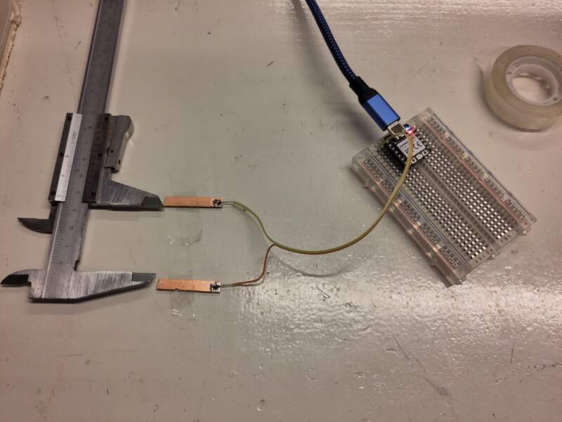
Week 9 — Input Devices
I experimented with all the inputs for my project this week:
- DCF77
- to get the current time
- Rotary Encoder
- to change the wake up time
- Step Response
- to detect a hand on the clock for snoozing
Week 10 — Output Devices
I experimented with making NeoPixel components for the clock digits, and using a piezo for sound. The latter was disappointing, I have decided not to use it.
Week 11 — Networking
More playing with NeoPixels; not applicable to my final project but I learned a lot about them.
Week 16 — System Integration
I finally started designing the entire project in this week.
2026-05-21 Milled PCBs for the clock/dock connectors
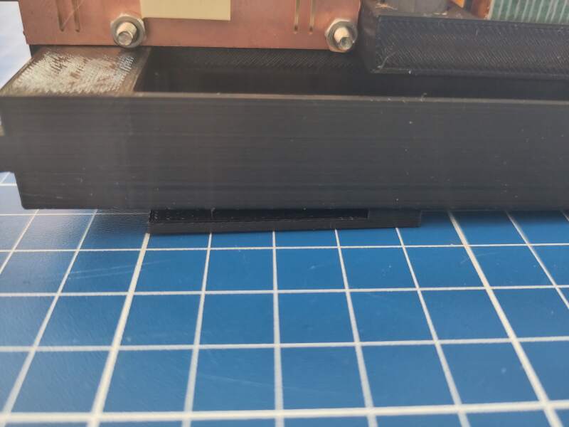
2026-05-23 Clock connector added to the main interior
I printed a stand that will be slotted into the housing which holds the clock connector to connect to the dock.
2026-05-25 Broke connector off the main board
While connecting the bottom part with the clock connector to the main board, I ripped off one of the connectors. I immediately re-milled the board and resoldered it.
While soldering, I printed some diffusers for the display to try out.
2026-05-26 Audio not working on 5V
Last night, I found out the DFPlayer Mini does not work when on battery power. The 5V pin does not supply 5V when the battery is attached. I destroyed the RP2350 while testing the voltage with a multimeter.
I also spent some time with V-Carve and OpenSCAD to create toolpaths for milling the housing. I am planning on doing that next Friday.
2026-05-27 Switching to MAX98357A
I received the DFRobot MAX98357 I2S Amplifier Module - 2.5W in the mail today and immediately started testing it. Works great on 3V3!
The pin names on the board do not correspond to the I2S names in the MicroPython library. Here is the translation:
| Pin | MicroPython |
|---|---|
| BCLK | sck |
| LRCLK | ws |
| DIN | sd |
Also interesting: not all pin combinations are allowed. I got a
ValueError: invalid ws (must be sck+1) error on the first try.
Eventually I was able to produce a tone and play a WAV file I uploaded
to the RP2350 using mpremote. After confirming it worked, I spent
(a lot of) time making a footprint and adjusting the symbol in KiCad
to update the main PCB.
During class, I decided to drop using the Shopbot for the housing because the multiplex I have is too uneven to get reliable pockets for the acrylic windows and PCB frame. I discussed it with Henk and will go with fully laser-cut acrylic.
2026-05-28 Milling another main board
I milled a new main board with the MAX98357 on it today but alas, the footprint I made yesterday is 2.54mm too wide. Next time, I will print the PCB on paper first when including self-made footprints to see if they actually fit. So, I corrected the footprint and milled yet another board.
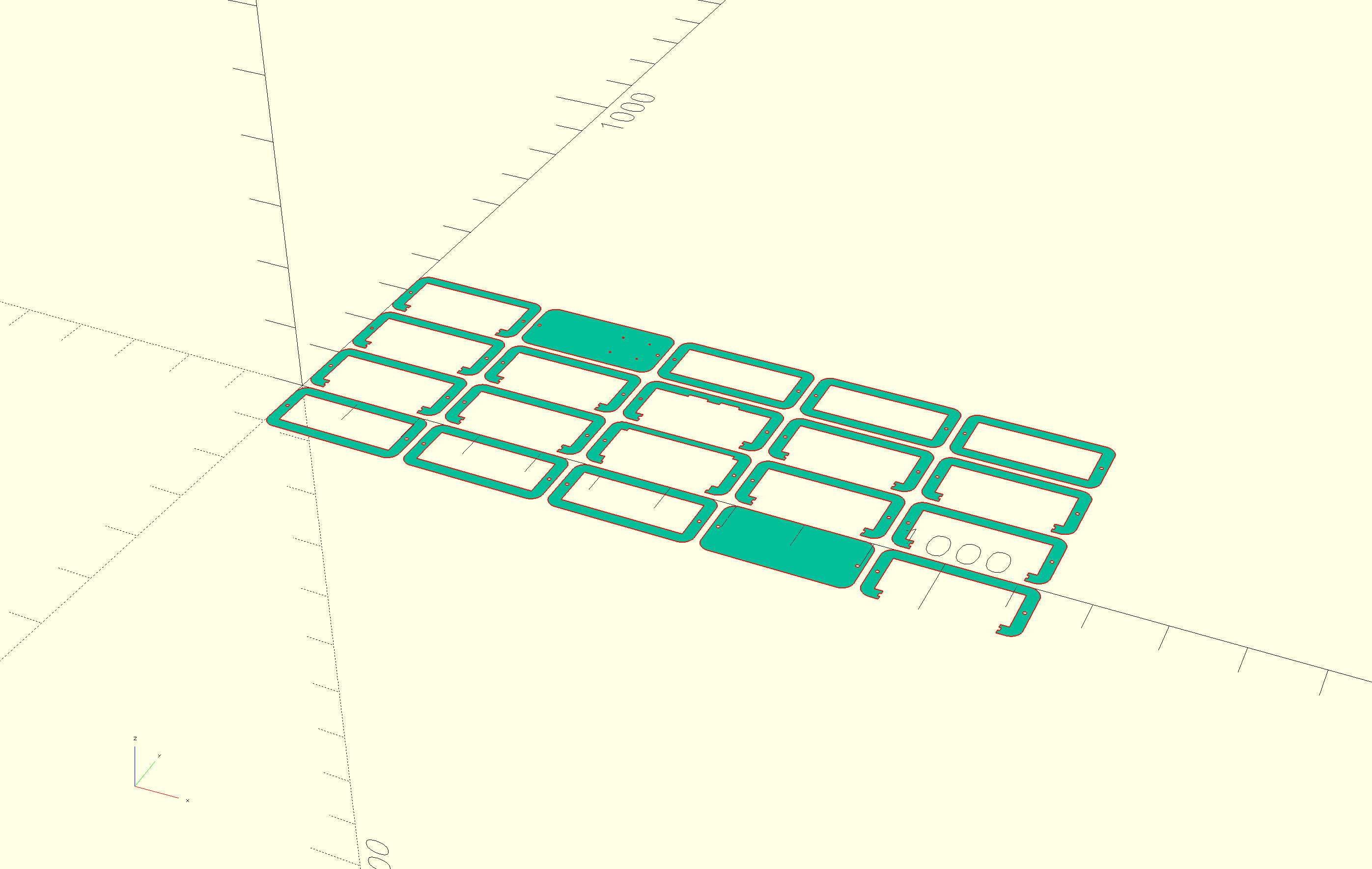
2026-05-28 Laser cutting the housing
Today was "LightBurn and burn-smell day"! It was more fun than I imagined. I did a cardboard test first, then the faces in wood (very pretty!), then the windows in clear acrylic, and finally the rest of the shell in white because the cardboard was not sturdy enough.
The first cardboard test failed. Somehow, DeepNest messed up the scale of the SVGs, so I dropped DeepNest and nested the parts myself in LightBurn.
Settings used:
| Power % min/max | Speed | |
|---|---|---|
| Cardboard | 20/30 | 100 |
| Wood | 90/100 | 25 |
| Acrylic | 65/75 | 10 |
I mismeasured the thickness of the acrylic, so the intermediate slices are too thick. I can probably fix the interior to make it fit (new frame and base), so I'll look into that this weekend.
2026-05-30 Acrylic housing and dock drafting
Today I cleaned up the acrylic slices for the body (removing the protective foil and clean them with soap to get rid of the smell left by laser cutting). Although the slices are too thick, they are already usable without reprinting the internals. I was afraid the white of these rings would not be as pretty as the cardboard, but it looks very nice.
The rest of the day I spent on designing a dock. Extra points for being able to print it on my Prusa Mini (180x180x180mm).
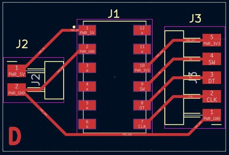
2026-05-31 Printing the dock and changing the connector pin order
Printed the model I designed yesterday and updated the connector boards to have a more logical pin order, making it harder to flip power and ground when docking it the wrong way.
2026-06-01 Creating new connectors, shopping for parts and DCF77 trouble
Got some threaded 5mm rod to bolt the housing slices together (unfortunately, the shop was out of bolts long enough). I also worked on the 3D models of the clock and dock base because I need USB access without taking it apart all the time. I milled the dock connectors to get a better pin layout and created new wires to match.
During the long 3D print, I looked at why the DCF77 does not work on RP2350 (it does on the RP2040!). I found some hints on an old blog post (hurrah for the wayback machine!). But, after adding a (real) pull up resistor and a capacitor as in the example, still nothing happened. I tried switching to 5V, nothing. More pull up by enabling the onboard pull too, nothing. I'm giving up for now, printing a new clock base with USB access should allow me to set the time (many with Web Serial page to do so?).
Annoying, low-progress day..
2026-06-02 Finishing the hardware and starting video editing
It has been a long and busy day. I printed (and reprinted) the dock base for the new pin layout and connector position. In the second print, I made the footprint of the dock slightly narrower to avoid pins bridging each other when connecting (I probably need diodes on the V and GND pins).
I sawed the threaded rod to match the clock thickness and filmed putting the clock together in a couple of takes. Kdenlive is a bit harder to use than I imagined, but I can probably make a short video.
For music I found Ambient Cinematic by AtlasAudio on pixabay.
The USB worked awesomely but broke after putting the clock together for the 5th (?) time…
2026-06-03 Software and step response
I spent a lot of time writing the firmware today. All the logic is in place, but when it's packaged up and the sound is playing, the step response is very unreliable. It is unworkable because it is impossible to detect a hand on the clock. Need sleep, will fix tomorrow.
2026-06-04 Fixed it with aluminum foil and made a movie
I fixed the step response by extending the pads to the outside of the housing using aluminum foil. A hand on the clock is now a lot easier to detect!
Plenty more tweak of the firmware and I downloaded some alarm sounds from Pixabay:
In the evening (low light), I filmed my son using the alarm clock, and edited it into the presentation video.
Technical overview
Bill of Materials
The following parts are used to build this project:
| Amount | Description | Price | Sum | Function |
|---|---|---|---|---|
| 1 | SEEED STUDIO XIAO | 5.75 | 5.75 | Main / RP2350 |
| 1 | DCF77 | 2.69 | 2.69 | Main / Radio Clock Receiver |
| 1 | DFR0954 | 7.02 | 7.02 | Main / Audio source |
| 1 | Speaker | 1.50 | 1.50 | Main / Audio output |
| 1 | RES 0 OHM JUMPER 1/4W 1206 | 0.10 | 0.10 | Main / Electrical |
| 1 | RES 1K OHM 1% 1/4W 1206 | 0.10 | 0.10 | Main / Electrical |
| 1 | Makerfocus 3.7V 3000mAh Lithium | 15.00 | 15.00 | Main / Battery |
| 20 | SMD Socket headers | 0.75 | 15.00 | Main / Connectors |
| 1 | SMD Pin headers | 3.33 | 3.33 | Main / Connectors |
| 1 | USB-C extension | 3.65 | 3.65 | Main / Connectors |
| 0.1 | ColorFabb PLA Highspeed PRO Jet Black | 21.55 | 2.15 | Main / Frame |
| 30 | ADDRESS LED SERIAL RGB | 0.25 | 7.50 | Display / Light |
| 4 | CAP CER 1UF 50V X7R 1206 | 0.25 | 1.00 | Display / Electrical |
| 0.05 | ColorFabb XT Clear | 21.55 | 1.08 | Display / Diffusion |
| 1 | 3mm Clear Acrylic | 5.00 | 5.00 | Clock / Housing |
| 1 | 4mm White Acrylic | 20.00 | 20.00 | Clock / Housing |
| 1 | KY-040 Rotary Encoder | 2.44 | 2.44 | Dock / Time selection |
| 1 | CONN SPRING MOD MALE 6POS SMD | 1.95 | 1.95 | Dock / Connector dock |
| 1 | CONN SPRING MOD FEMALE 6POS SMD | 1.92 | 1.92 | Dock / Connector clock |
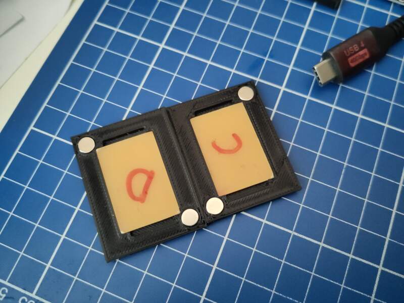
| 4 | Magnets | 0.70 | 2.80 | Dock / Placement |
| 1 | USB-C PD Fast Charging | 1.67 | 1.67 | Dock / Power |
| 1 | PCB FR-1 stock | 20.00 | 20.00 | Main, Clock and Dock |
| Total ex. VAT | €121.65 |
The SBOM (Software Bill of Materials) is not that interesting. I used:
- MicroPython 1.28
- steptime.py by Neil Gershenfeld
- micropython-dcf77 (currently not used due to RP2350 DCF77 issues)
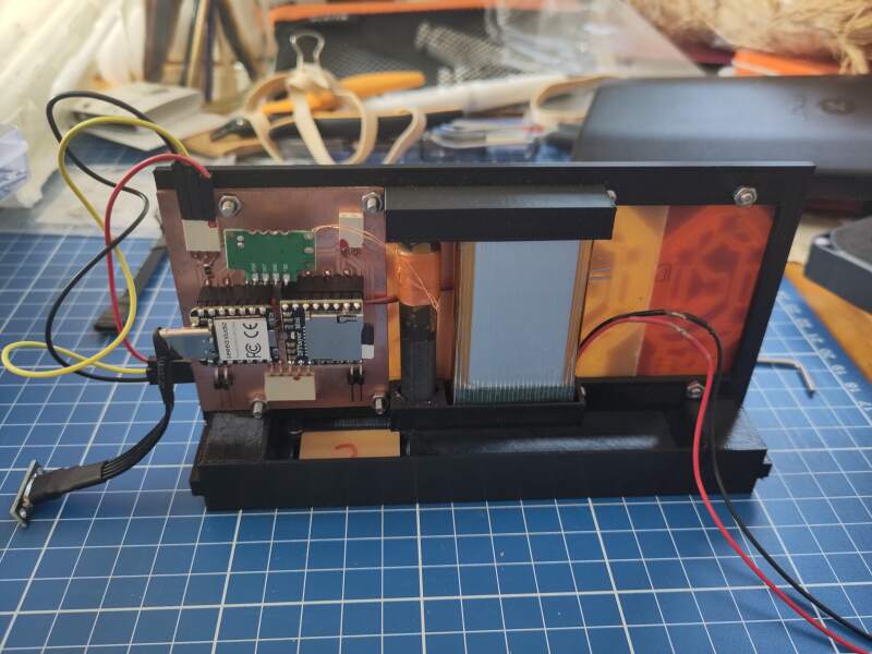
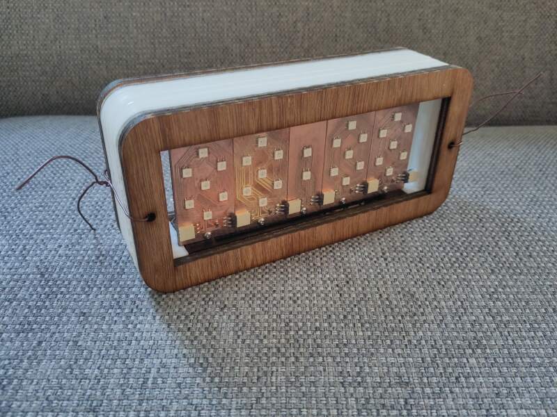
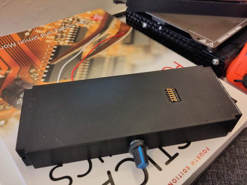
Clock
The clock contains all the "live" components: display time, sound alarm, and run on battery.
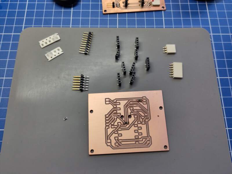
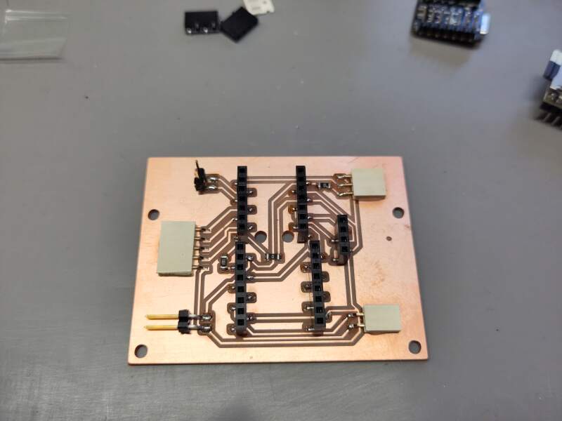
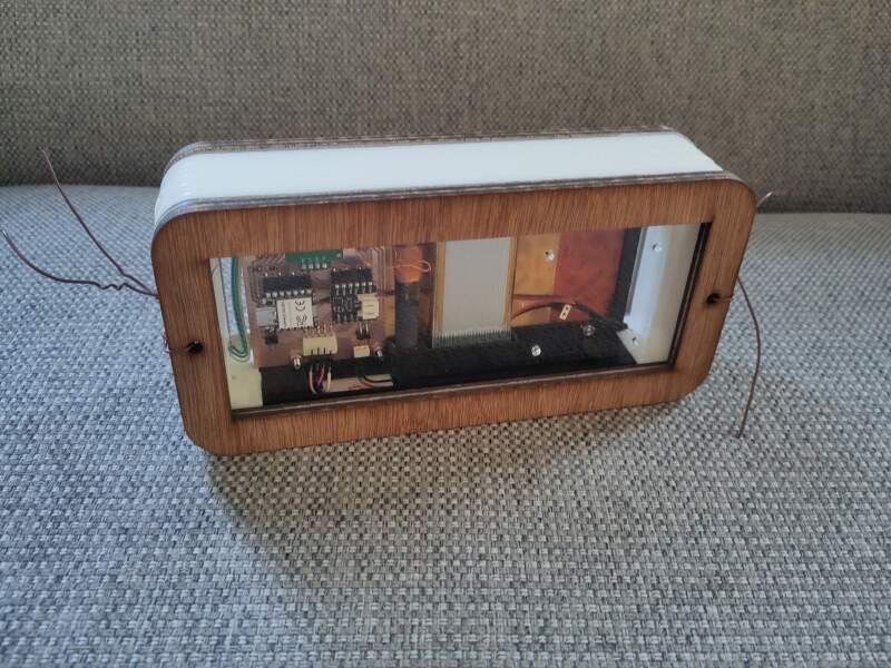
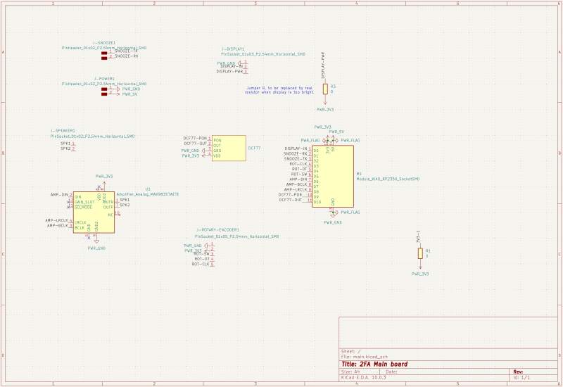
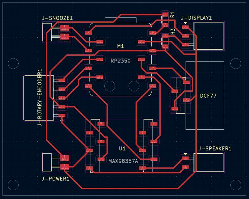
Main board
The main board has sockets for:
- Microcontroller (RP2350)
- DCF77 (clock receiver)
- MAX98357A (audio amplifier)
and connectors for:
- Display
- Power (5V)
- Speaker
- Rotary Encoder
- Snooze detection (Step Response)
Sources:
Time keeping
To keep the clock time accurate the DCF77 transmission will be used. Time will be sync on power-on, and daily readings should be enough to keep the clock in sync for an alarm clock.
Unfortunately, I could not get it to work on the XIAO RP2350. Weirdly, it works fine using a XIAO RP2040, but that XIAO does not support batteries out of the box.
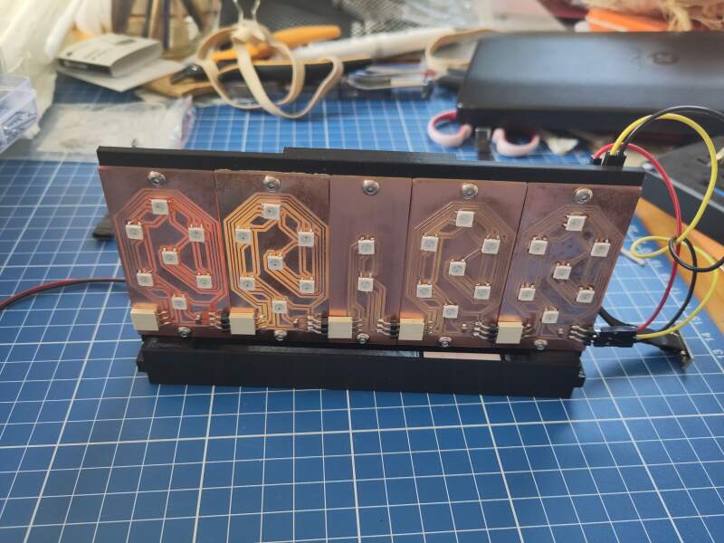
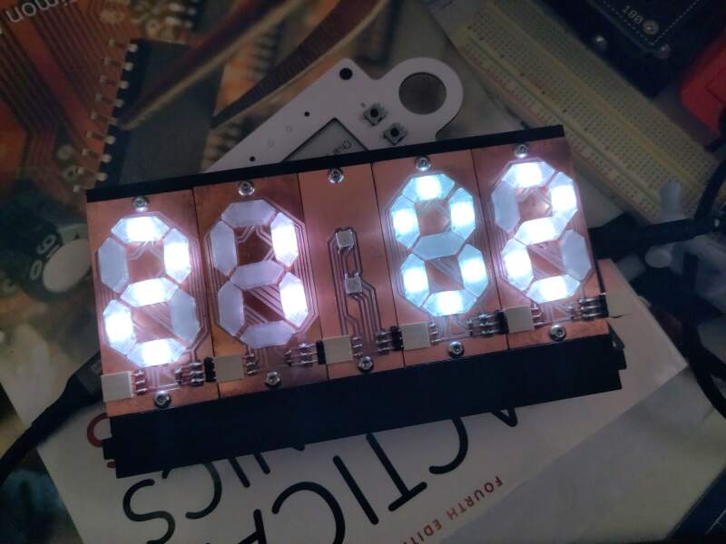
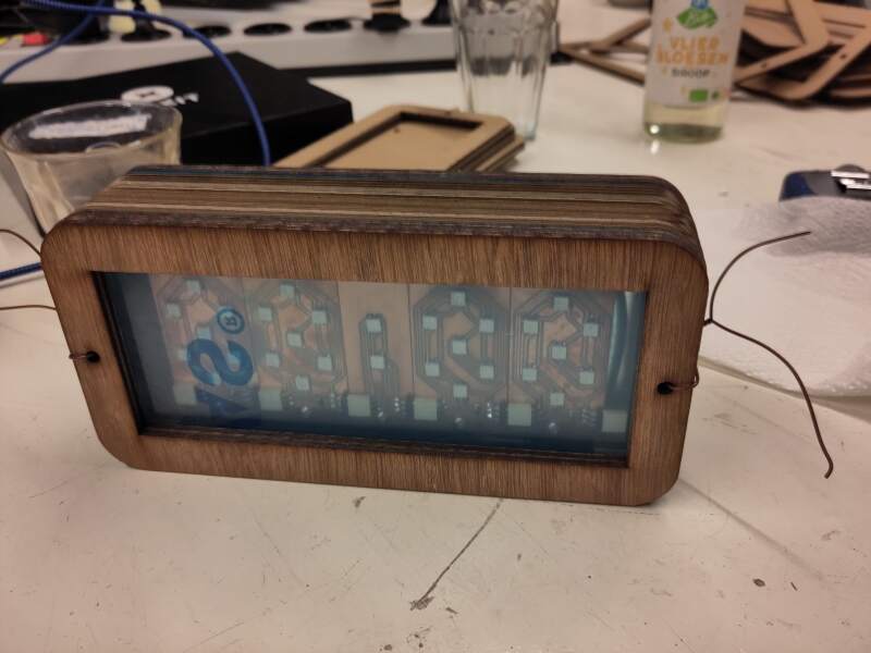
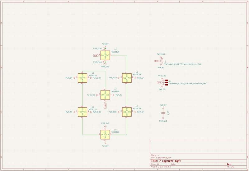
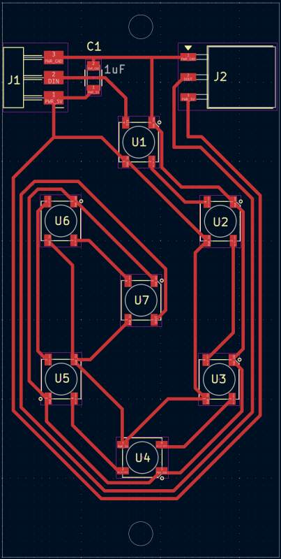
Display
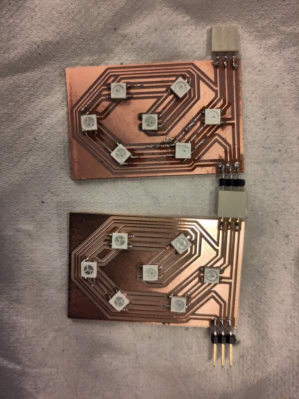
The digits will be NeoPixel modules based on the design for week 10. I wanted to have the pixels shine through wood, but decided that would be an awful time drain, and making a box that looks interesting is quite hard. The PCBs are quite pretty, so I'll make them visible instead.
The improved design is a 35x65mm board with a 25x45mm digit. It also has one 1µF capacitor between the VDD (5V) and VSS (ground) as instructed in the datasheet (100nF per LED). The "dots" board will not have any capacitors because (I hope) the capacitors on the digit boards will be more than enough.
Sources:
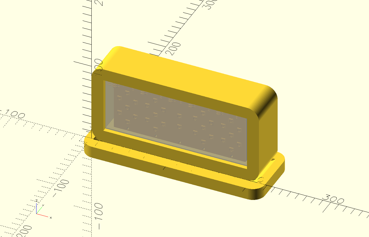
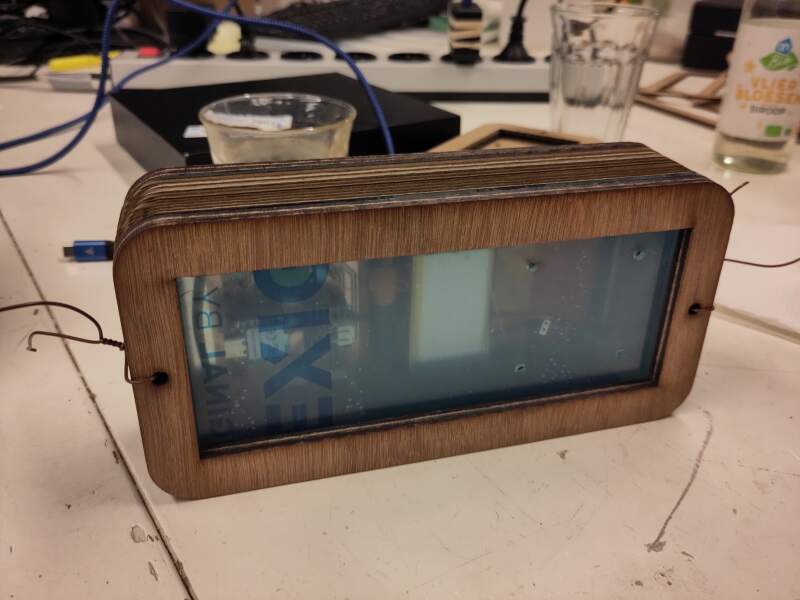
Segment mask / diffusion
For diffusing the light of the NeoPixels, I printed the model below using ColorFabb XT Clear (a PET-like filament).
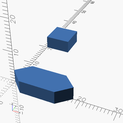
The resulting diffusion is pretty bad, but I do not have time to experiment with this.
Wake up Sound
For sound, I first decided to use the DFPlayer Mini. It can play MP3 files, has a build in amplifier, and supports TF cards (aka mini SD) for storage. For output, I got a 57mm, 8Ω, 0.5W speaker. Unfortunately, running it on battery power failed because the player needs 5V to operate and attaching the XIAO RP2350 to a battery makes the 5V pin useless.
So, I switched to the much simpler MAX98357.
Snooze
The alarm can be snoozed by triggering a step response change using your hand via two conductive pads hidden in the top of the clock.
Actually, when I was putting the clock together, I found out it is very hard to detect a change when the alarm sound is playing because that triggers a lot of noise in the step-response setup. I fixed this (MacGyvered it) by enlarging the pads with aluminum foil, which sticks out of the top of the clock. There was not enough time to change the housing to fix this properly.
Power
The XIAO RP2350 has onboard battery management (XIAO RP2040 does not) and can be connected to a lithium battery and charge it. When USB is disconnected, it will automatically switch to battery power. The battery level can be read from GPIO29 (see also pin map). The battery must have power protection (PCM) to avoid over(dis)charging.
The V5/VUSB/VBUS pin can be used to power the XIAO without using the USB port. To protect the VBUS it is smart to add a diode but that's already on the XIAO circuit (see also XIAO with Lipo Battery Charging Circuit).
The 5V power for charging will from the docking station.
Connect/disconnect stability
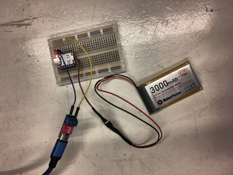
I used the code below to test power breaks. This code was installed
as main.py, so it starts up after a reset.
import machine, time, ws2812

machine.Pin(23, machine.Pin.OUT).value(1)
led = ws2812.WS2812(22, 1)

led.pixels_fill((128, 0, 0))
led.pixels_show()

time.sleep_ms(2000)
led.pixels_fill((0, 0, 128))
led.pixels_show()
For testing, I connected 5V through a PD Board (B0DPHHK5ZV) with a lithium battery (Makerfocus 3.7V 3000mAh Lithium) attached. Running the code above, it was easy to detect whether the RP2350 resets because the LED will turn red for 2 seconds and then back to blue.
Findings:
- (Dis)connecting USB power causes no breaks.
- (Dis)connecting 5V power causes no breaks.
- Disconnecting the battery on USB/5V power only breaks power on the first disconnect.
Detecting on USB power
The GPIO29 pin can be used to gauge the battery power state (don't forget to set GPIO19 to high). Below is the code I used to see if it is possible to detect whether the board is powered by battery or from an external source.
import machine, time

# turn on battery power reading
machine.Pin(19, machine.Pin.OUT).value(1)

# pin to read battery power values
adc = machine.ADC(29)

n = 0
while True:
    v = adc.read_u16()
    print(n, v)

    time.sleep_ms(1000)
    n += 1
Unfortunately, it seems impossible to reliably detect, with the code above, to detect whether the external power source is attached using the code above. I was expecting to see a big power drop when the external source is detached but the value just keeps fluctuating as it did before.
Interestingly, the code example in the Seeed OSHW repository does not return realistic voltage values.
from machine import Pin, ADC
import time

# Function to initialize the GPIO pin for enabling battery voltage reading
def init_gpio():
    enable_pin = Pin(19, Pin.OUT)
    enable_pin.value(1)  # Set the pin to high to enable battery voltage reading

def main():
    print("ADC Battery Example - GPIO29 (A3)")

    init_gpio()  # Initialize the enable pin
    adc = ADC(Pin(29))  # Initialize the ADC on GPIO29

    conversion_factor = 3.3 / (1 << 12)  # Conversion factor for 12-bit ADC and 3.3V reference

    while True:
        result = adc.read_u16()  # Read the ADC value
        voltage = result * conversion_factor * 2  # Calculate the voltage, considering the voltage divider (factor of 2)
        print("Raw value: 0x{:03x}, voltage: {:.2f} V".format(result, voltage))
        time.sleep(0.5)  # Delay for 500 milliseconds

if __name__ == '__main__':
    main()
The above outputs:
ADC Battery Example - GPIO29 (A3)
Raw value: 0x8b98, voltage: 57.58 V
Raw value: 0x8ab8, voltage: 57.22 V
Raw value: 0x8aa8, voltage: 57.20 V
...
I created a bug report on GitHub and the friendly people of SEEED fixed it a week later!
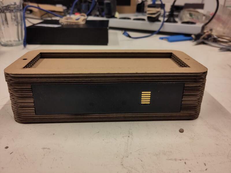
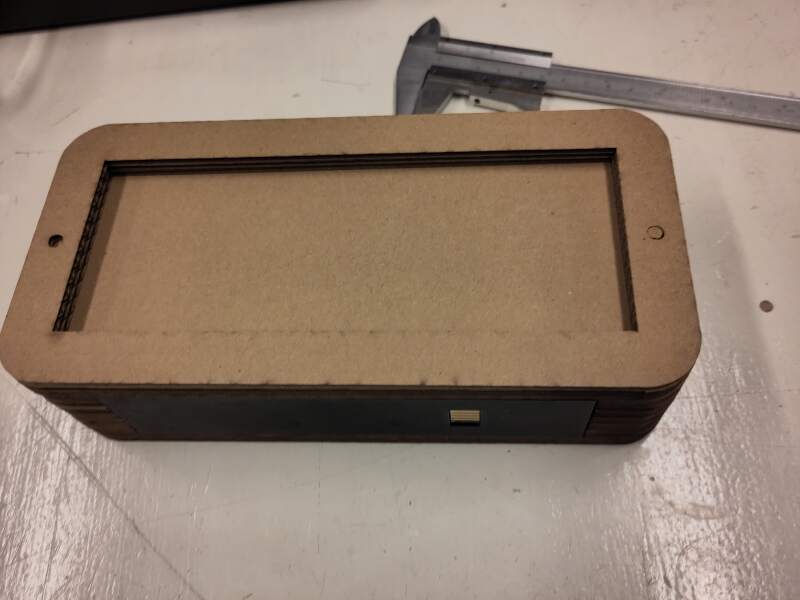
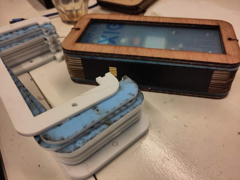
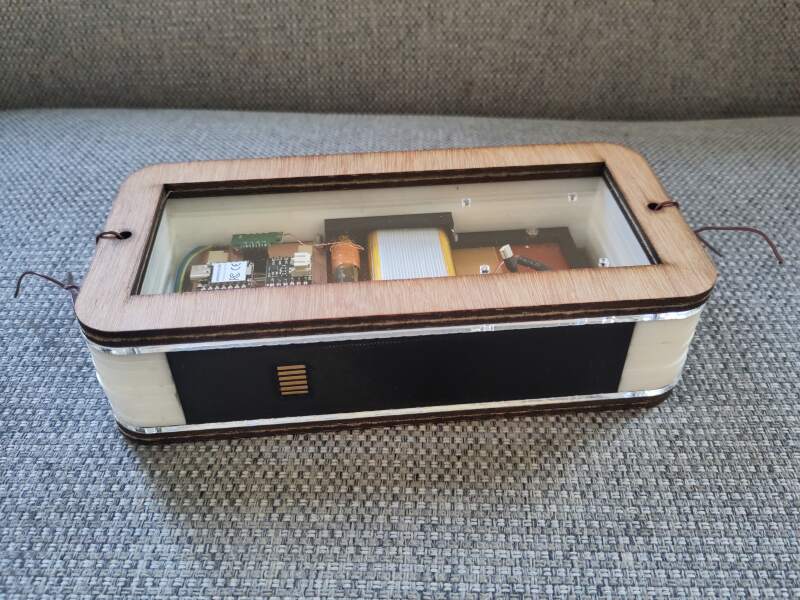
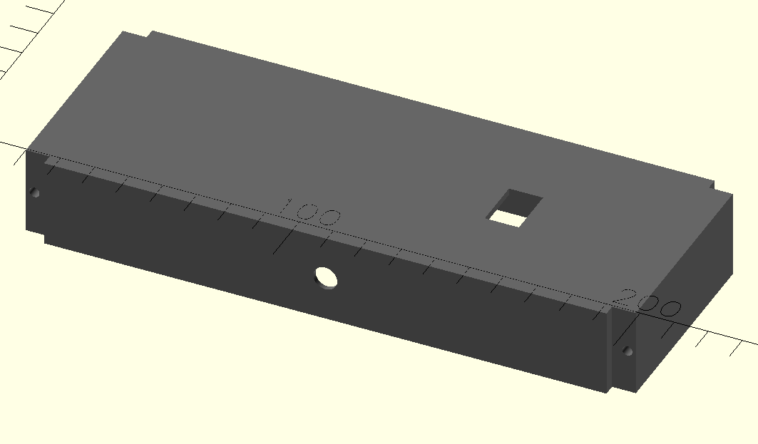
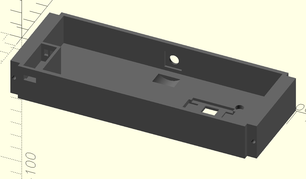
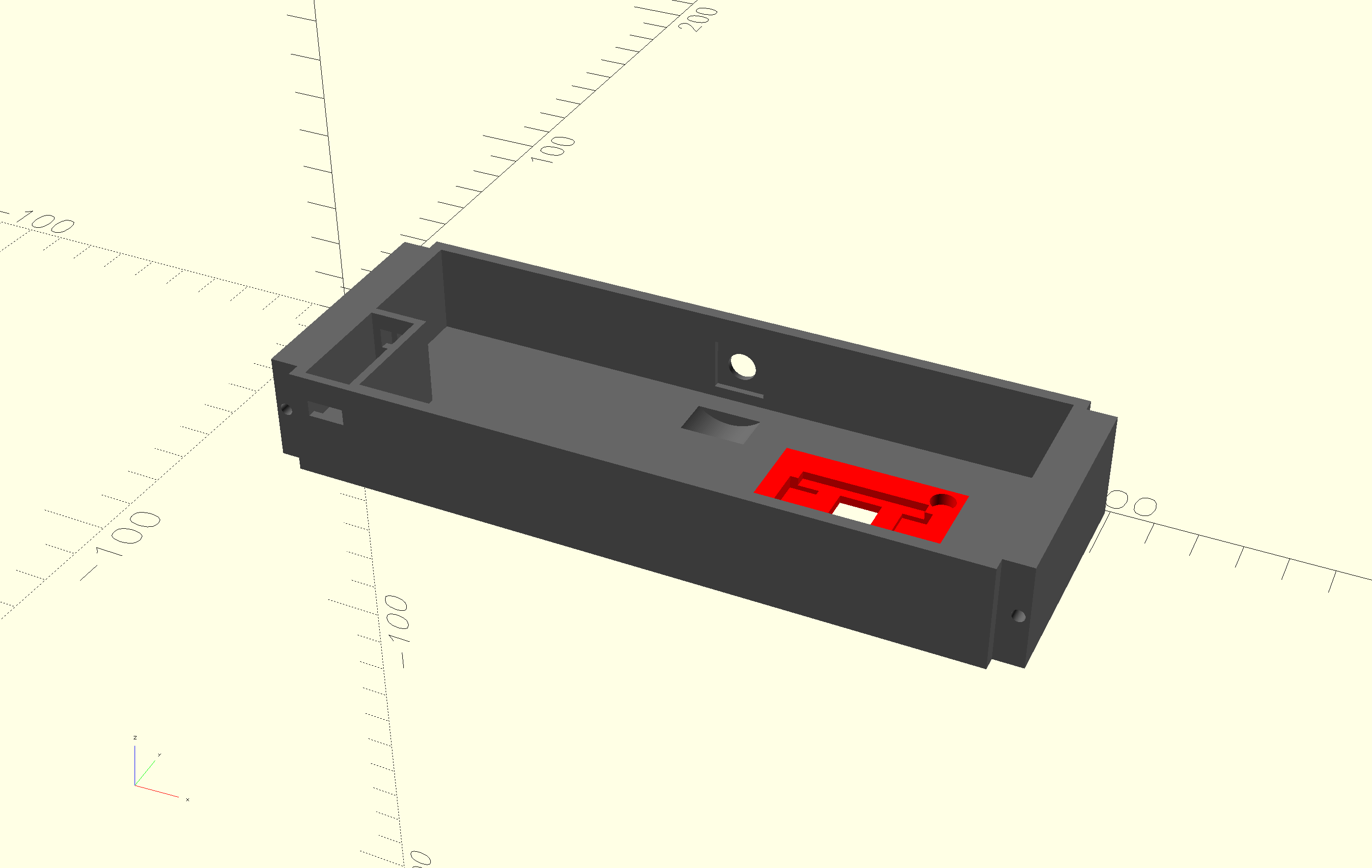
Housing
The housing of the clock consists of laser-cut slices of acrylic and triplex held together with a 5mm bolt and lock nuts. Inside, the PCBs are mounted to a 3D printed-frame. The bottom of the clock is also 3D printed; it holds the frame and a PCB for the connector to dock.
All prints and cuts are derived from a single all-in-one OpenSCAD file.
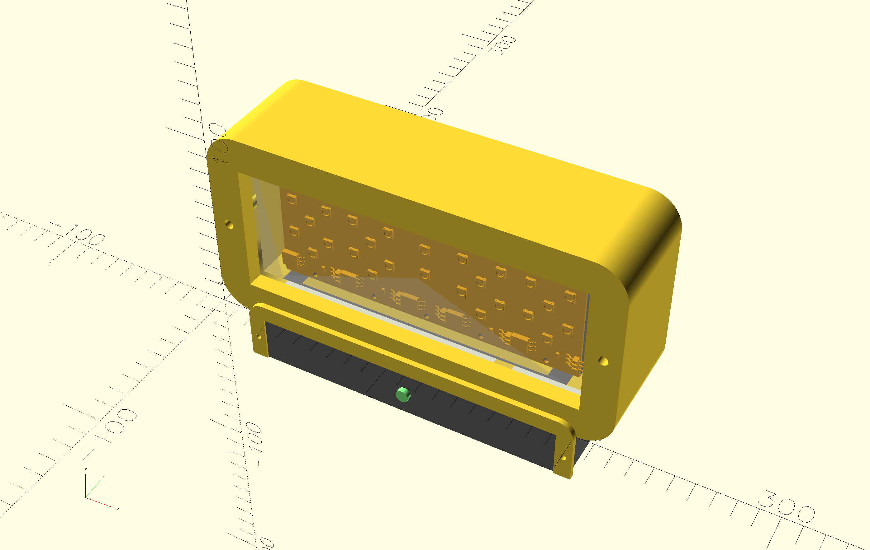
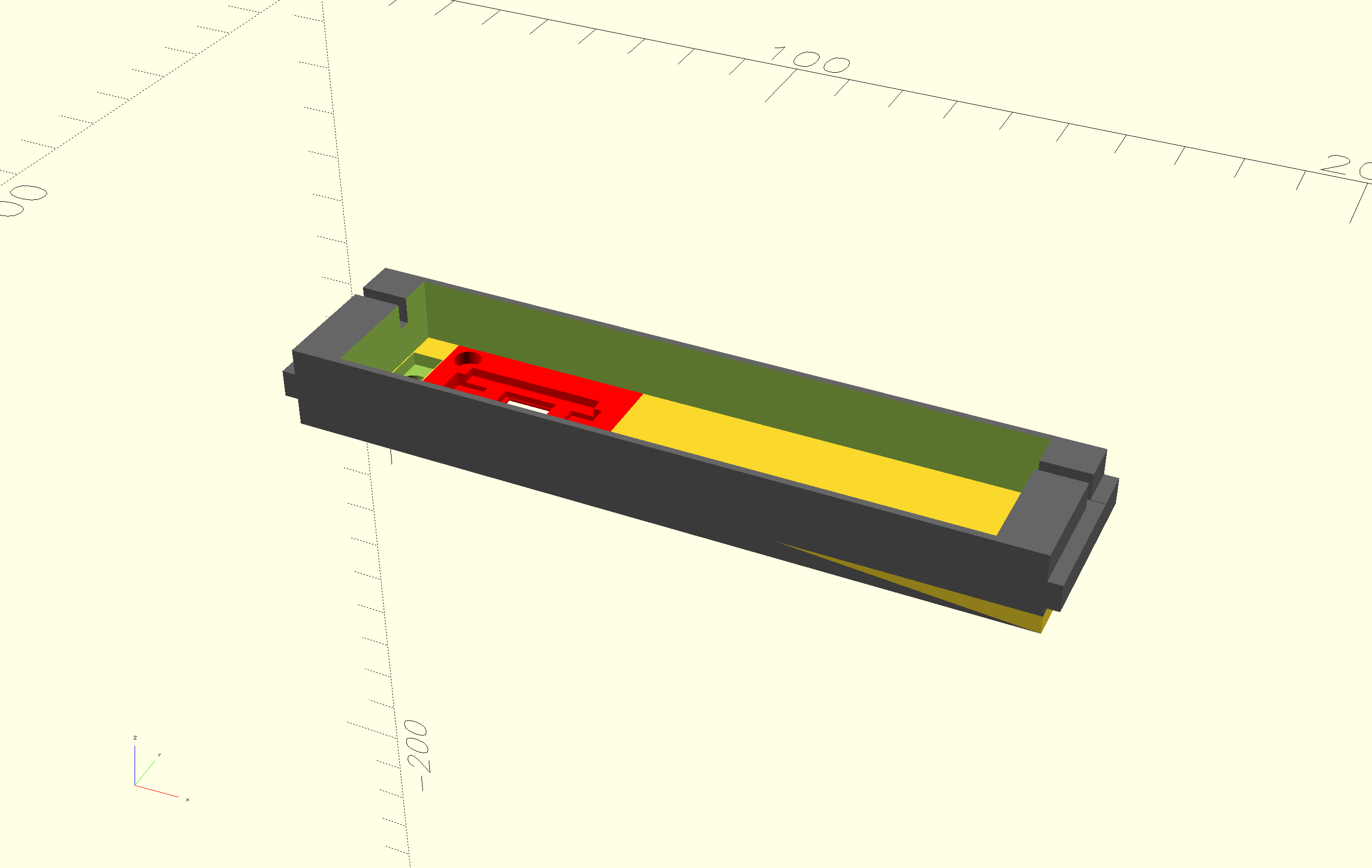
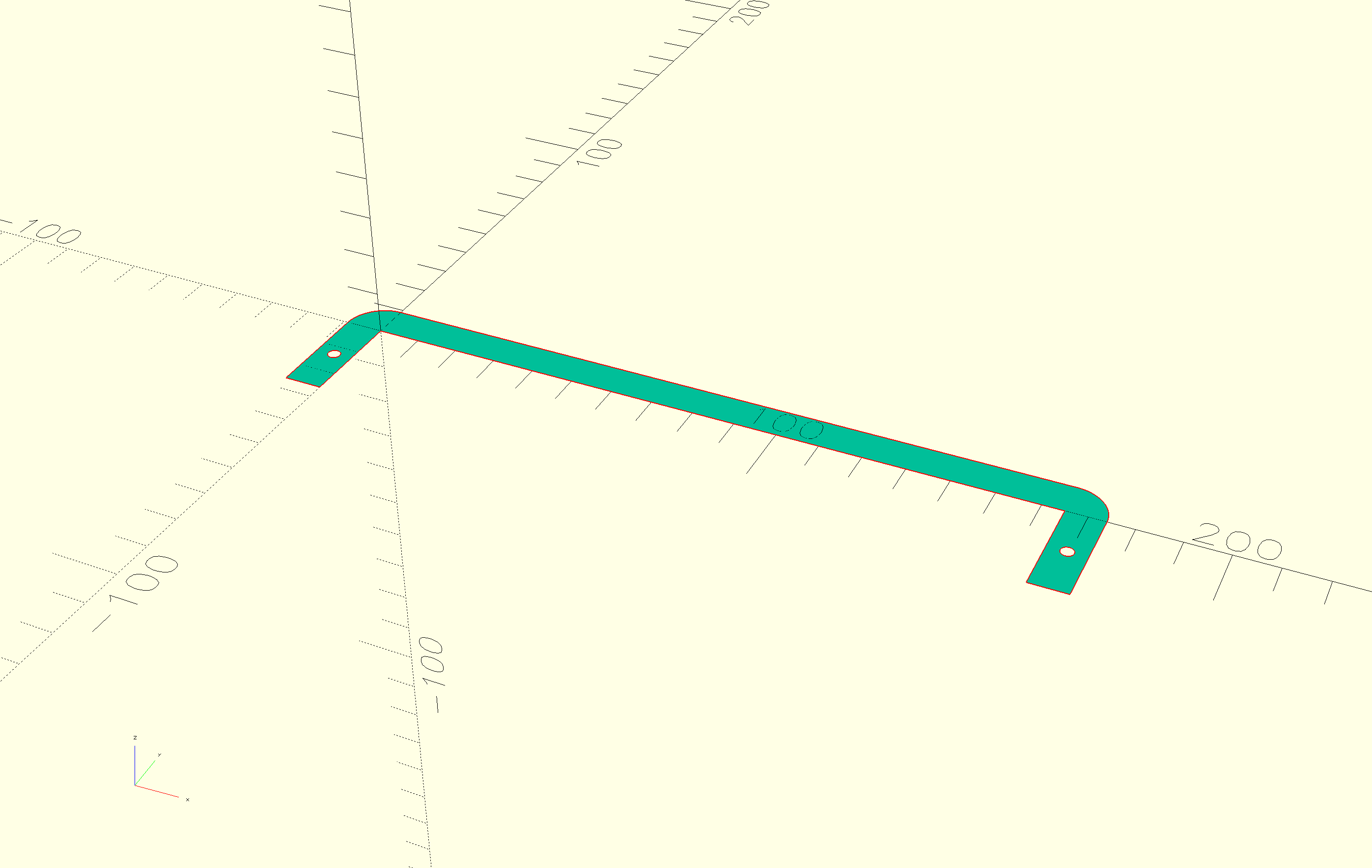
Here are the STL and SVG files:
Firmware
I used MicroPython to write the software. It is very easy to use and allows REPL (Read-Evaluate-Print Loop) development, which I prefer for experimentation. Apart from the stock MicroPython library, I only used the steptime.py library written by Neil Gershenfeld.
The code is split into modules:
-
Allows setting the NeoPixel digits and dots on the display in different colors.
-
Runs a periodic timer to probe the value of the snooze step-response detection (using steptime.py) and triggers a callback when the threshold is exceeded. This polling can be enabled/disabled to preserve power.
-
Uses an IRQ trigger on rising and falling pin values for the rotary encoder data pin. These values are translated to key pressed / released and (counter) clockwise rotation callbacks.
-
Drives the MAX98357 amplifier using I2S to play sounds in the background in a loop, and allows stopping them.
-
A simple wrapper around a Python list to push and pop events. The pop function has the ability to timeout and thus return
Nonewhen nothing happened. The callbacks in the snooze and rotary encoder modules push events onto this list. -
The main logic is implemented here. It's an event loop which supports the following modes:
sleep
The alarm is set and the display shows the current time with the dots blinking every second in a soft color. When wake-up time matches the current time, move to alarm mode.
alarm
The alarm is sounding and the display shows the current time in a bright color. When the snooze is triggered and the maximum amount of snoozes is not yet reached, turn off the alarm sound and move to the snooze mode. When the rotary encoder switch is pressed, turn off the alarm sound and move to dock mode.
snooze
The time is displayed in a soft color, but the dots are blinking brightly. When the snooze time is up, move to the alarm mode. When the rotary encoder switch is pressed, move to dock mode.
dock
Displays the current time in a soft color without blinking the dots. When the rotary encoder switch is pressed, move to the wake up hours mode.
wake up hours
The wake up time is displayed in a soft color with the hours in the bright color. Rotating the encoder changes the hours, pressing the switc,h moves the mode to wake up minutes.
wake up minutes
The minutes are highlighted and can be adjusted using the rotary encoder. Pressing the encoder, moves the mode to sleep.
Pressing the rotary encoder switch for more than 5 seconds resets the microcontroller. When it starts up, the current time must be set in a similar fashion to the wake-up time, but using another bright color (green). This should be replaced by setting the time using DCF77.
-
Load
twofac.pyand start the event loop.
Apart from the code, the following sounds are also part of the firmware:
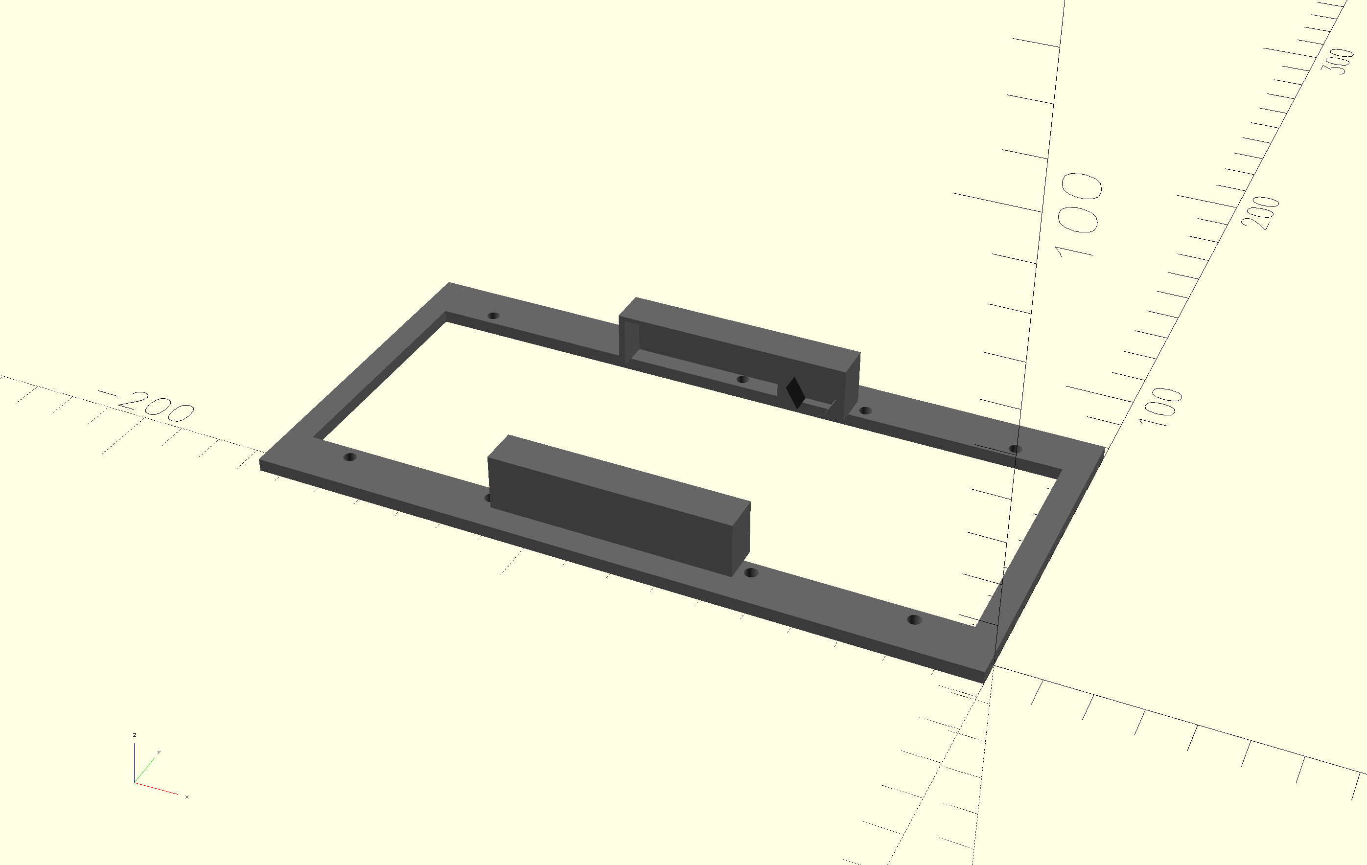
Docking station
The dock is a simple 3D-printed box with acrylic screwed onto the sides to guide the clock into the right position. I wanted it to be bigger, but I printed it at home on my Prusa Mini, so I was constrained by the 18x18cm print bed.
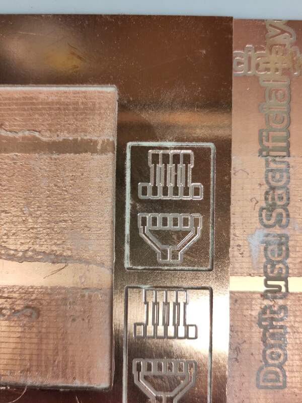
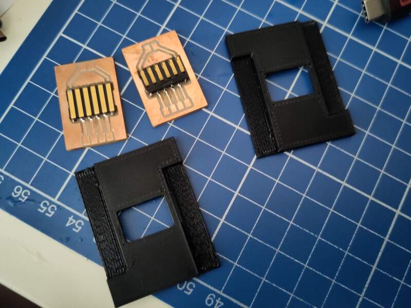
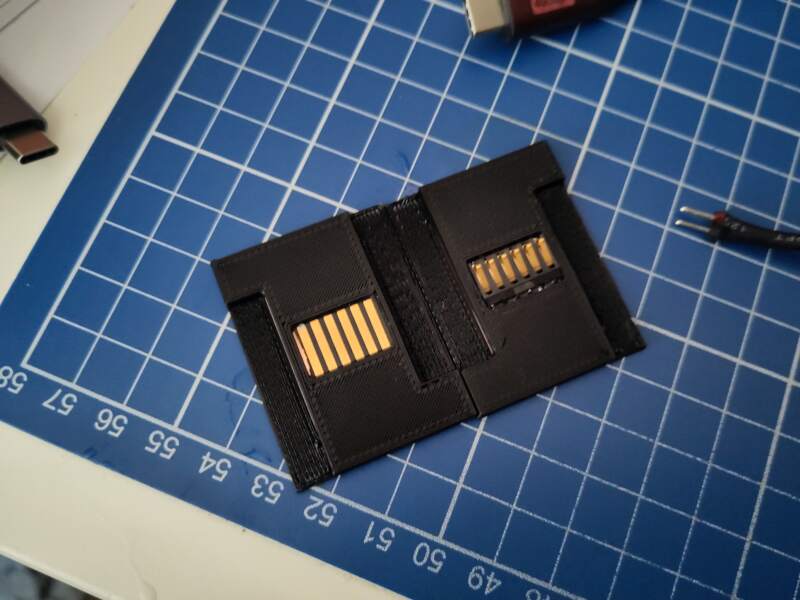
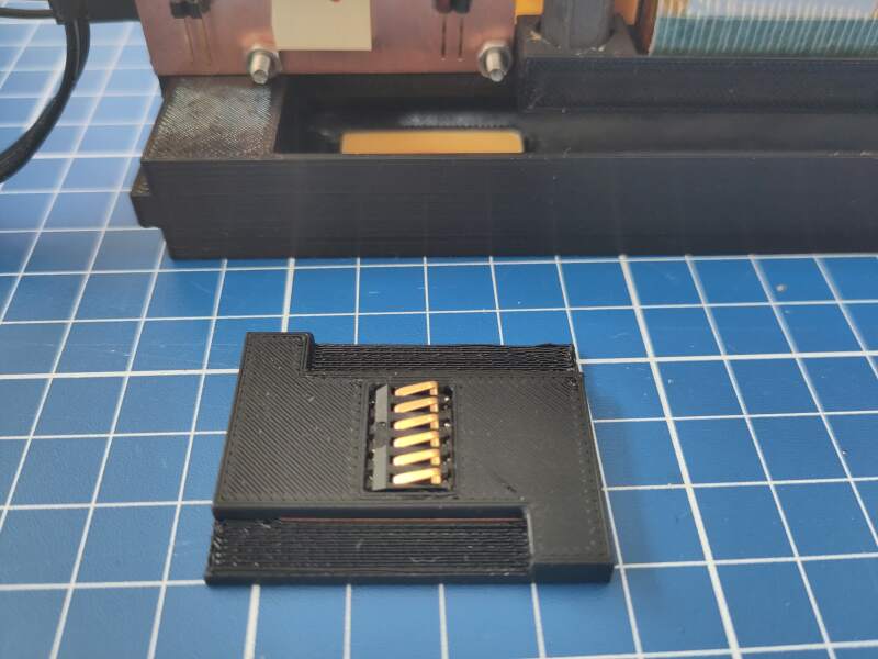
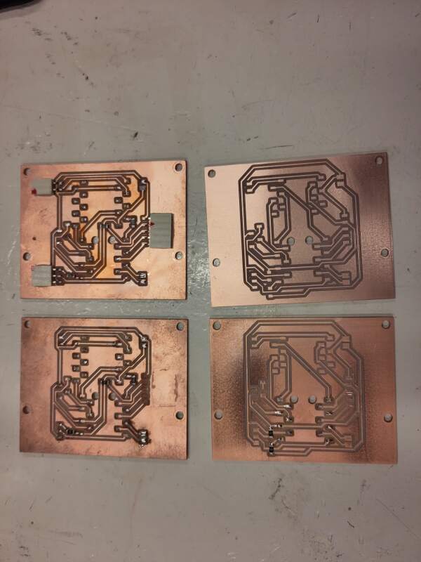
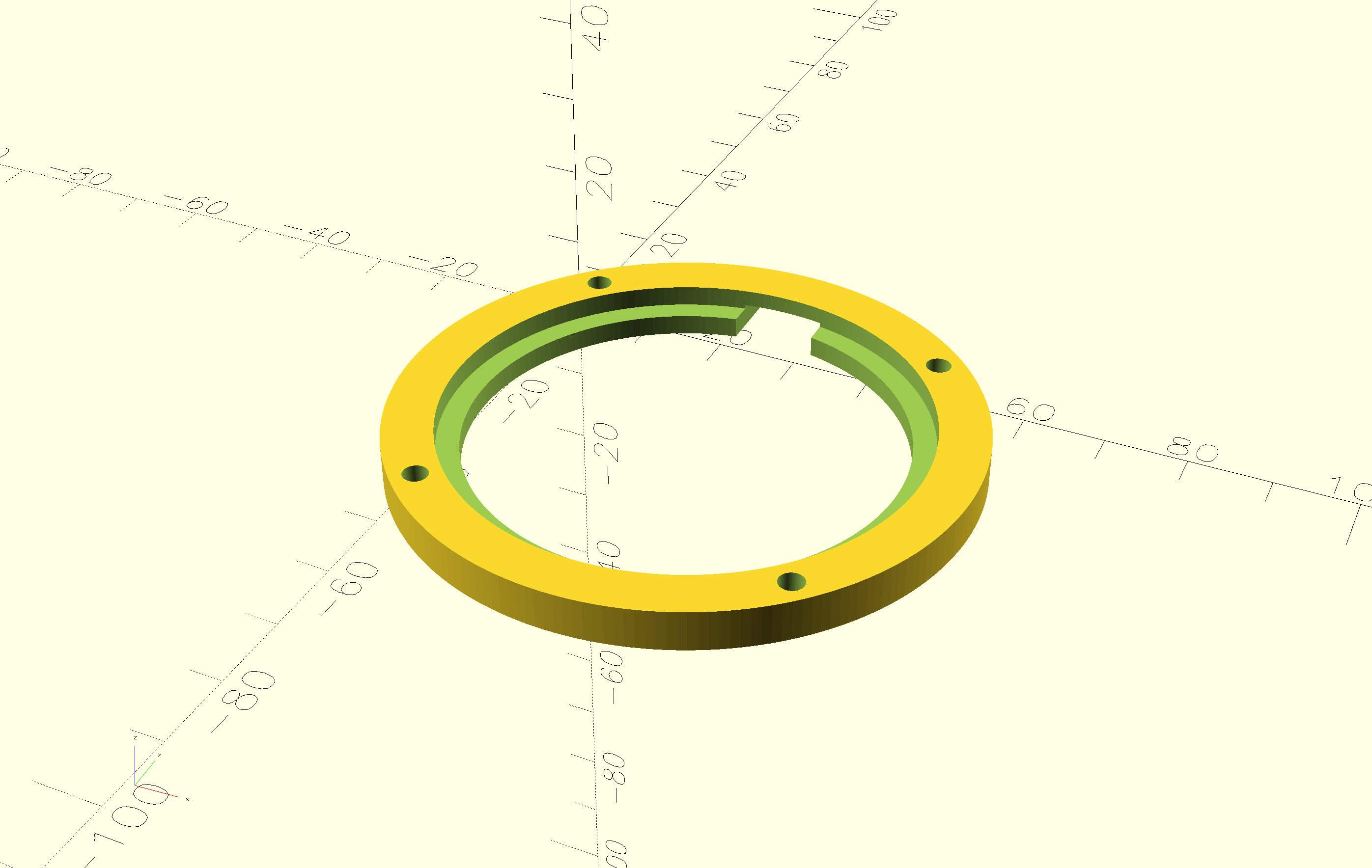
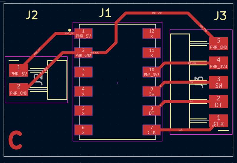
Connector
The connector passes power and exposes the rotary encoder pin to the clock. I used the following parts:
Parts:
I created PCBs for the clock and dock side of this:
Power
Power is provided with a PD Board (B0DPHHK5ZV) to use a USB-C cable to provide 5V to the clock for charging the battery. It is embedded in the dock and provides power through the connector. At first, I was afraid to mount the clock on the dock with the USB cable connected for fear of smoke, but it works very well!
Encoder
A commonly used rotary encoder registers rotation and clicks from the dock to the clock.
Evaluation
Having spent much time on this project, I am pretty happy with the result, but there is still a lot of room for improvement. I finished it a couple of days before the deadline but have no energy left to work on these issues. Here are a couple of things I would like to improve:
The DCF77 does not work on the RP2350. I spent hours trying to get it to work but nothing success. I may try a XIAO ESP32 I have laying around, which also supports battery charging, to see if that works, or use an RP2040 and add some charging circuitry. This is really bugging me.
The step-response approach I envisioned for the snooze function is now "MacGyvered" using aluminum foil. Experimenting with step response in the input devices week already gave me an uncertain feeling about this technique, and having it in a box packed with electronics confirmed that step response can be quite challenging.
Making something pretty requires more care in material selection than I gave this project. The PCB copper is on full display because I think it looks nice, but there is a lot of color variation and fingerprints on it. Also, the PCBs and the rest of the interior are stained by superglue fumes; it is very ugly, and it is still outputting this white coating after several days.
The NeoPixels vary in color and brightness because they come from three different batches. They are also too bright, so I should have experimented with adding a resistor to the power line. I did introduce a 0Ω resistor in the schematic and the PCB to do that, but did not try changing it because it works now and I don't want to break it. Also, the diffusion parts I printed don't work very well. It is hard to see what time it is in a bright room. I need more experimentation on that, too.
USB access to the microcontroller is very convenient for debugging but at least as convenient is the ability to reset and put it in boot mode (to allow flashing it with a new UF2-file) without taking it about would be really nice too. In a next iteration that would be very nice.
The dock is too lightweight and should be mounted on something like wood to make it more stable when operating the knob.
Reflection
Fab Academy was awesome! It's been a wonderful experience in which I met amazing people, and learned an incredible amount of new skills. A big thank you hug to everybody involved!
Footnotes:
Currently not working due to issue with DCF77 module and the RP2350
