Scanning and Printing
1. Week Assignments
Group Assignment:
- Test the design rules for your 3D printer(s)
- Document your work on the group work page and reflect on your individual page what you learned about characteristics of your printer(s)
Individual assignment:
- Design, document and 3D print an object (small, few cm3, limited by printer time) that could not be easily made subtractively
- 3D scan an object (and optionally print it)
2. Prior Knowledge
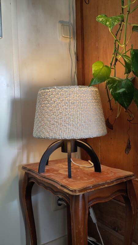
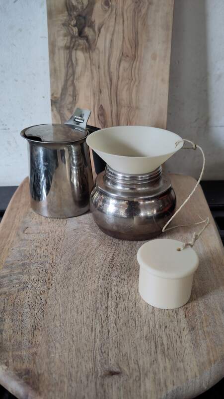
I own a Prusa Mini+ and have printed many things. Here are a couple of photos.
3. Work!
3.1. Group work
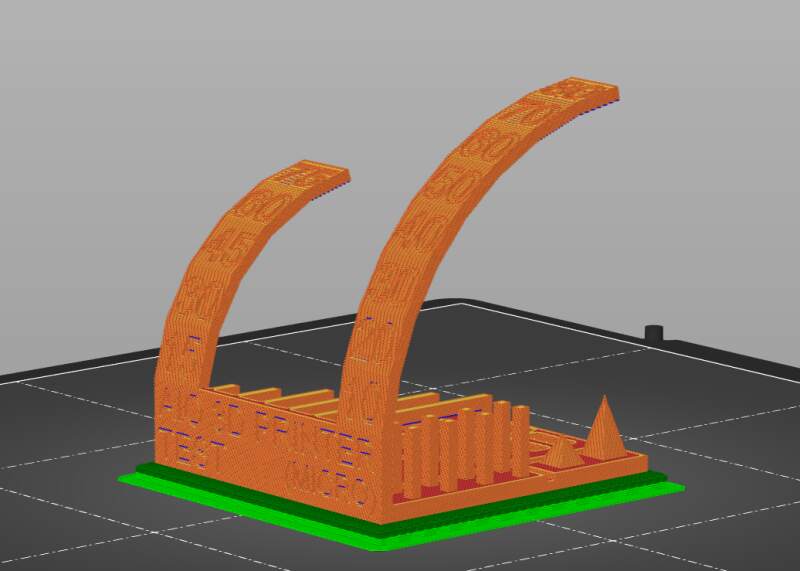
At the lab, we (tried) printing this all-in-one test model on:
- Prusa MK3
- Prusa Core One
- Creality Ender 3
- Ultimaker 2+
We setup PrusaSlicer to have presets for the above printers and all filaments include. Having all filaments is actually very annoying because it makes selecting the right filament finicky.
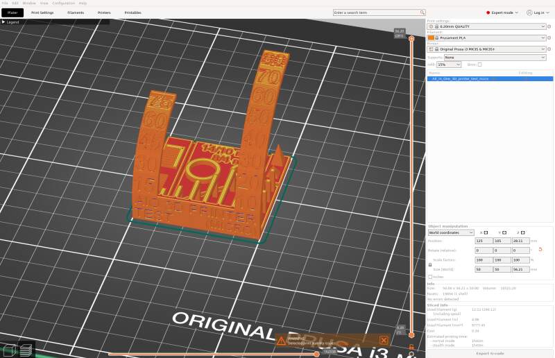
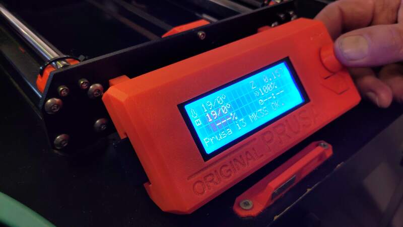
3.1.1. Prusa MK3
Ihe MK3 looks a bit like my Prusa Mini+ at home. The control display is a bit less modern, but I can do automatic bed leveling (with a Prusa INDuction Autoleveling sensor module), so it should not be that hard to use. It uses 1.75mm filament.
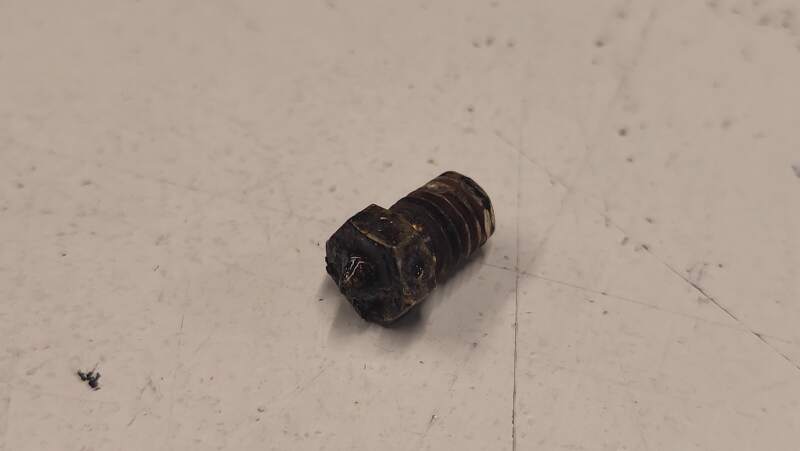
Unfortunately, it was clogged. After a couple of layers, the extrusion would stall, and no more filament would come out of the nozzle. Purging the nozzle with PLA several times did not help. Henk fixed it in the evening by replacing the nozzle.
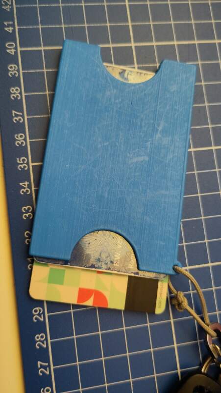
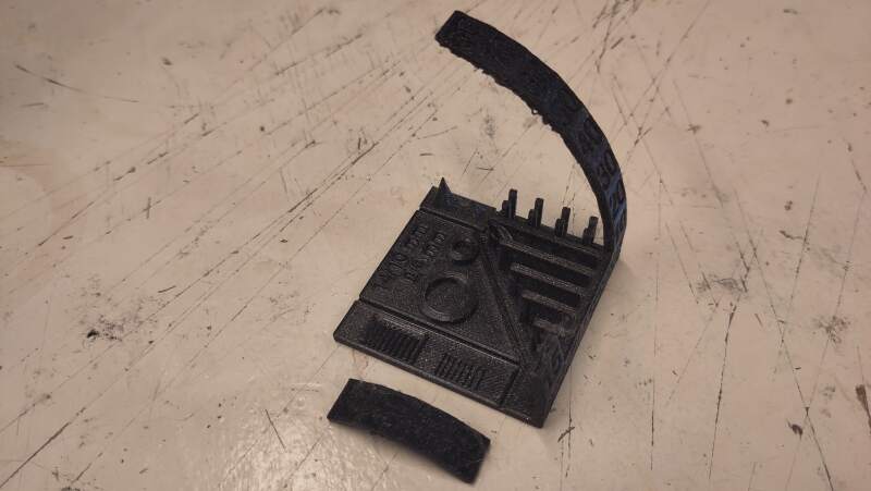
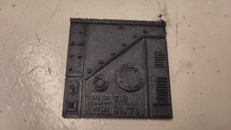
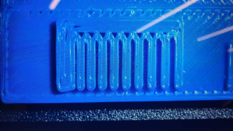
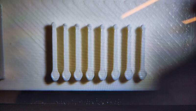
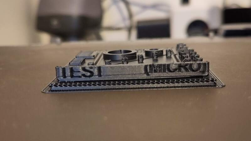
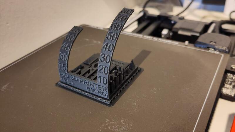
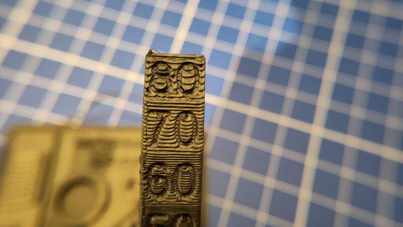
Henk printed the all-in-one model on this machine. Below are some photos. Note that I broke off the right side overhang to photograph the tolerance test on the right using the microscope.
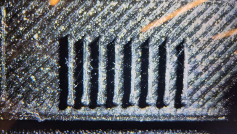
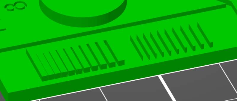
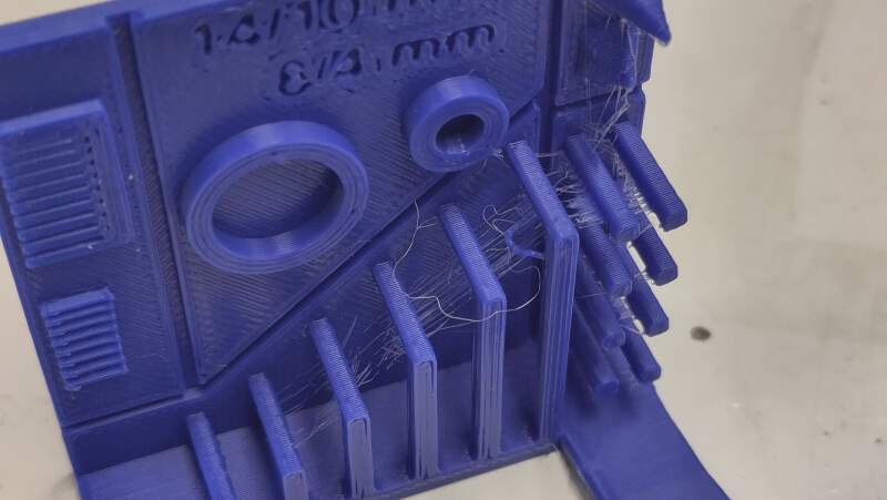
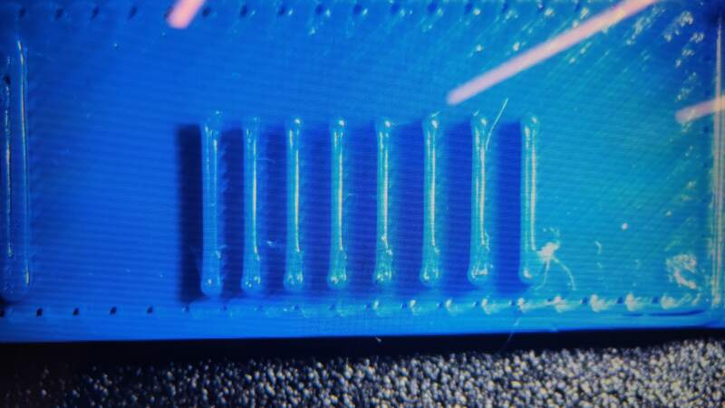
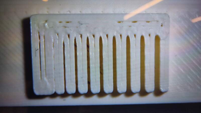
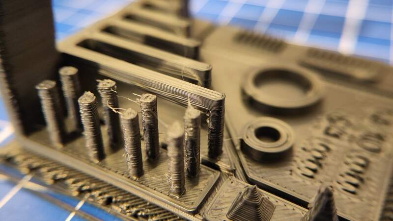
The ribs look very much the same. Looking at the model (see figure 6) these ribs should go from narrow to wider. Having a 0.40mm nozzle will probably never get us a nice gradient of ribs because they are too narrow.
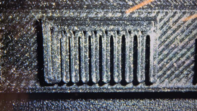
Interestingly, the slits to show a nice gradient. The movement on the X-Y-axis seems much more precise that 0.40mm
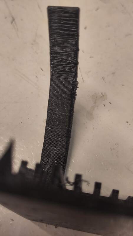
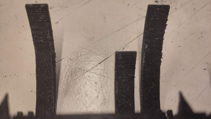
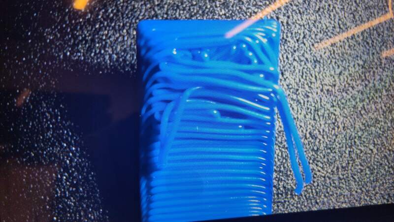
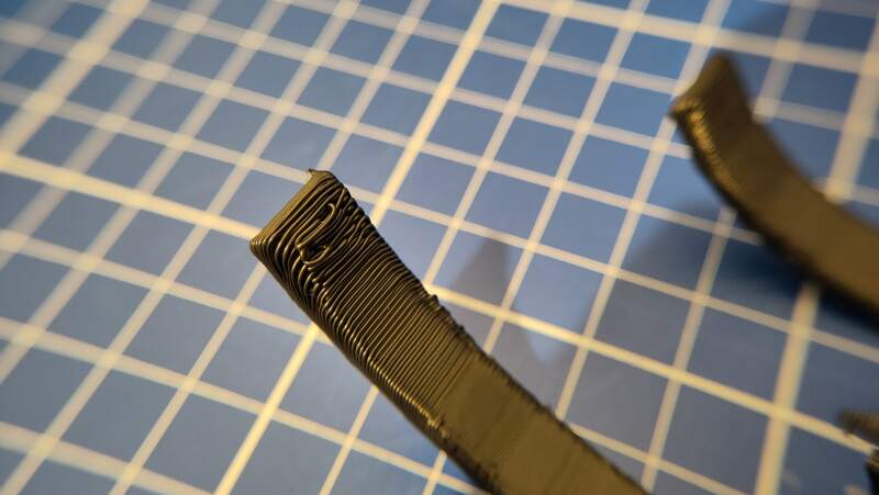
The result of the overhang was very stringy at to bottom and the sides. Henk sliced it for us and he changed the Nozzle temperature other layers setting to 220°C because the first prints he made had under-extrusion problems.
In the end, he fixed it by tightening the extruder idler crew, which regulates the tension between the cogs pulling in the filament.
We started another print with the value changed (back) to 215°C to see if the stringing disappeared and the extruder still functioned properly. The results had less stringing but the edge of the overhang test was still frayed.
We tried again with Filament overrides value Retraction length set
to 1mm (it is disabled by default), following a hint in an article
Henk shared. Unfortunately, it had no visible effect.
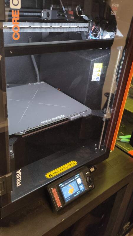
3.1.2. Prusa Core One
The Prusa Core One is a very fancy-looking machine with a closed case. It takes 1.75mm filament, and we used PLA. When printing PLA in this closed case, the ventilation grid needs to be open to allow cooling.
It just worked. This seems like a very reliable machine.
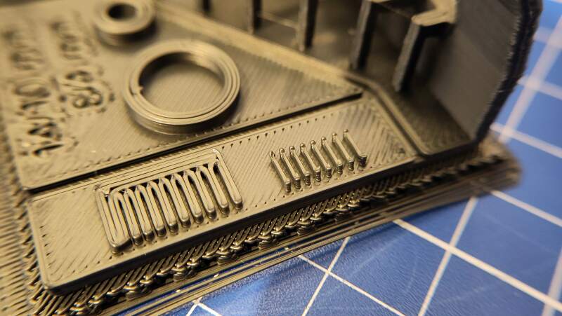
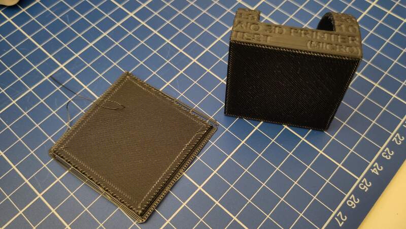
We printed the all-in-one model using "eco" PLA.
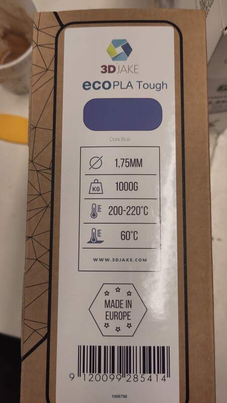
Here are some photos of the result.
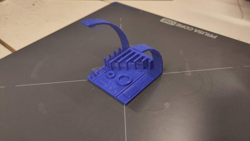
The sagging of the lines at 80° overhang is to expected and actually something PrusaSlicer warns about.
3.1.3. Creality Ender 3
It was very finicky to level the bed on the Creality Ender 3. It does have automatic bed leveling, the build plate is too big for the bed, and is held down by clips that can be run over by the nozzle. With help and instructions from Irja, we used a piece of paper (plain printing paper) to set the nozzle distance from the build plate using the adjustment screws on the bottom of the plate. The paper should lightly grip between the nozzle and the plate.
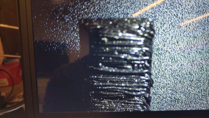
When the bed was finally leveled, we started the all-in-one print, but after a couple of layers, it stopped with a cryptic message on the control display about a heating failure. It seems like the temperature sensors do not work properly, and the controller panics.
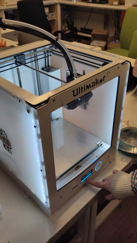
3.1.4. Ultimaker 2+
The Ultimaker looks very friendly. The bed leveling process was similar to the Ender 3, using paper and screws at the bottom. A plus for this machine is that it has a nice glass build plate. It uses 2.85mm filament.
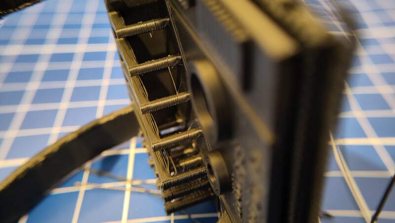
Our first prints failed. The nozzle would start hitting into the model after a while. It would move over the stalks on the right side and hit all of them.
After multiple bed leveling attempts, Heleen figured out (by comparing G-code from the SD card and G-code generated in her slicer) that we used the wrong setting for Filament Diameter. The G-code we applied was assuming 1.75mm, and thus pushing more filament per second, causing over-extrusion. The excess of PLA on the model would cause blobs to form on the stalks where the nozzle would run into.
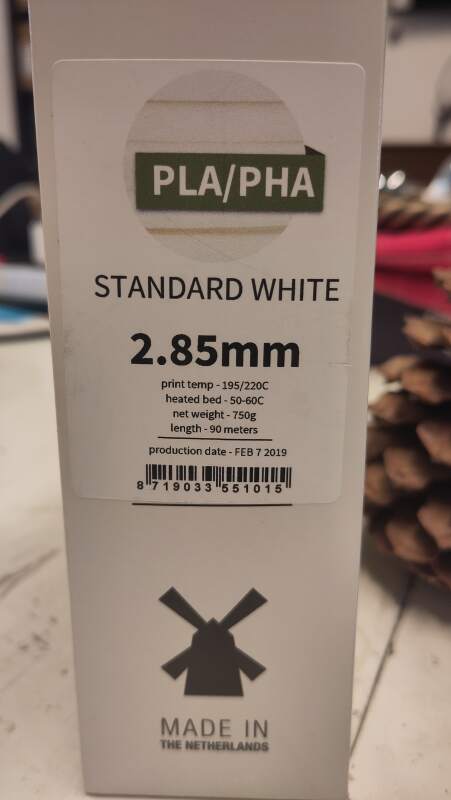
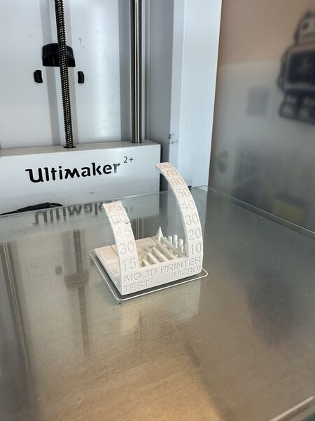
The next day, Christian made successful prints by adjusting the filament diameter in the slicer. He used colorFabb PLA/PHA "Standard White" to print it with the 0.12mm detail printer setting.
3.1.5. Prusa Mini+
At home, I have a Prusa Mini+ and some filaments I wanted to test using the all-in-one-test. Same machine, different filaments.
3.1.5.1. ColorFabb allPHA
I tried to do the all-in-one test for ColorFabb PHA because I know it has a tendency to warp when printing a large flat surface.
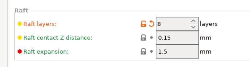
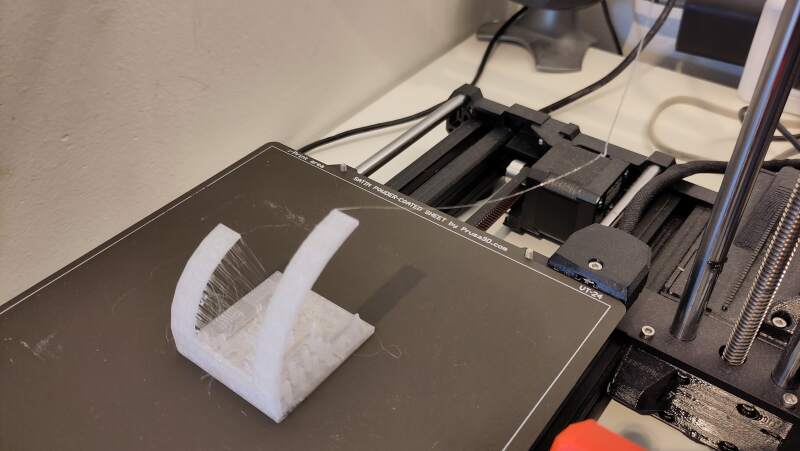
According to the datasheet, PHA should be printed on an unheated bed because heat will induce crystallization, which leads to uneven shrinking and warping of the bottom layers. In the lecture and local instructions, I learned about rafts, and inspired by somebody who printed PHA on supports, I wanted to see if the would help.
My theory was that the bed would not collect heat while printing, especially in the middle of the print causing uneven crystallization / shrinking. The raft should even out the heat.
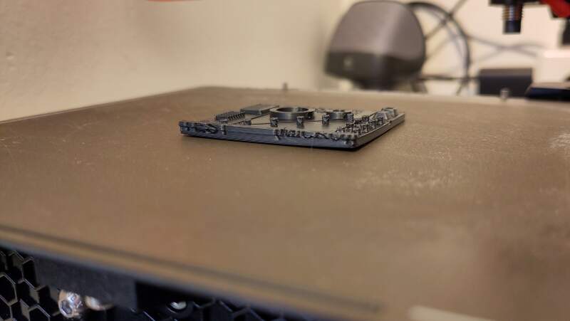
At the layer where the last print clearly failed, this print was looking good!
Adding a raft is a success!
The result is pretty good.
I was pleasantly surprised the raft came off very easily.
This was a success and a great addition to my personal PHA filament printing profile.
3.1.5.2. ColorFabb XP (PET)
After the PHA success, I decided to do the same for the role of clear ColorFabb XT (a PET variant) I have. I've had little issues printing it but was very curious about its performance on the all-in-one test.
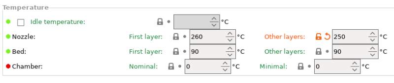
I started with the default profile for ColorFabb XT which is available in PrusaSlicer. Interestingly, the values for temperature deviate from what is on the datasheet.
| Prusa settings | Datasheet | |
|---|---|---|
| Nozzle | 260°C | 240-260°C |
| Bed | 90°C | 60-70°C |
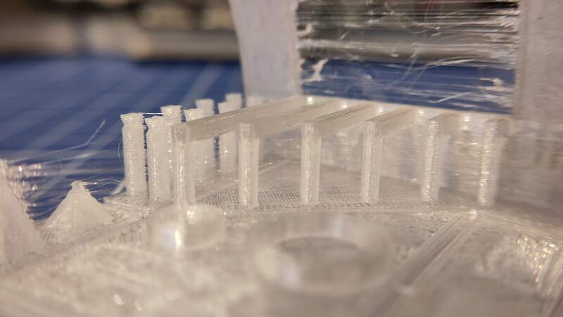
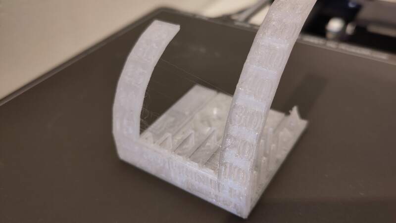
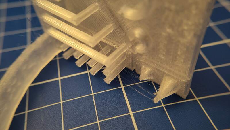
The result was very stringy and the filament oozed out of the head after the print.
The overhangs were very impressive compared to the PLA prints we did in the lab. It seems that PET has the right hardening / viscosity to make them?
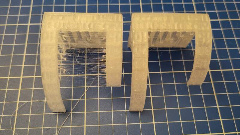
Following tips on the ColorFabb blog post about XT to reduce the stringing, I changed the Retraction length (was unset originally) and lowered the Nozzle temperature to 250°C on Other layers.
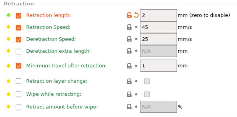
The resulting print is much better!
The filament still oozes out of the nozzle after the print is done, but that's not a problem.
3.1.6. Apples and Oranges
Making a comparison between the above machines based on these prints would not make any sense because we used different types of PLA. For the Ultimaker, we even used PLA/PHA, which has different properties from PLA.
Another mismatch is the usage of the 0.12mm detail printer setting for the Ultimaker and the default 0.20mm settings for the other machines.
The favorite machine among us students is the Ultimaker because it is built to be user-friendly and gives good results. When in a hurry, the Prusa Core One is the clear winner.
3.2. Bracelet 3D print
For the "could not be easily made subtractively" assignment, I wanted to make a bracelet made of segments linked through ball joints.
Here is the OpenSCAD script I came up with to generate a model for it.
$fn = 200;

inner_r = 5;
outer_r = 8;
spoke_r = inner_r * .2;
spoke_len = inner_r * 4;

tolerance = .4;
cone_r1 = 2;
cone_r2 = 10;

module segment() {
  difference() {
    union() {
      sphere(inner_r);
      hull() {
        cylinder(h = spoke_len + 2, r = spoke_r);
        translate([0, 0, spoke_len]) sphere(outer_r);
      }
    }
    translate([0, 0, spoke_len]) {
      sphere(inner_r + tolerance);
      translate([0, 0, -.25 * inner_r]) {
        cylinder(outer_r, cone_r1, cone_r2);
        translate([0, 0, outer_r]) cylinder(10, outer_r);
      }
    }
  }
}

rot = 20;

module go(i) {
  if (i >= 0) {
    segment();
    translate([0, 0, spoke_len]) rotate([rot, 0, 0]) go(i - 1);
  }
}

rotate([0, 90, 0]) go(360 / rot);
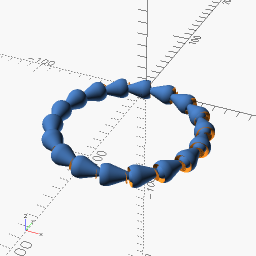
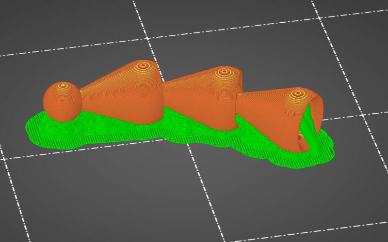
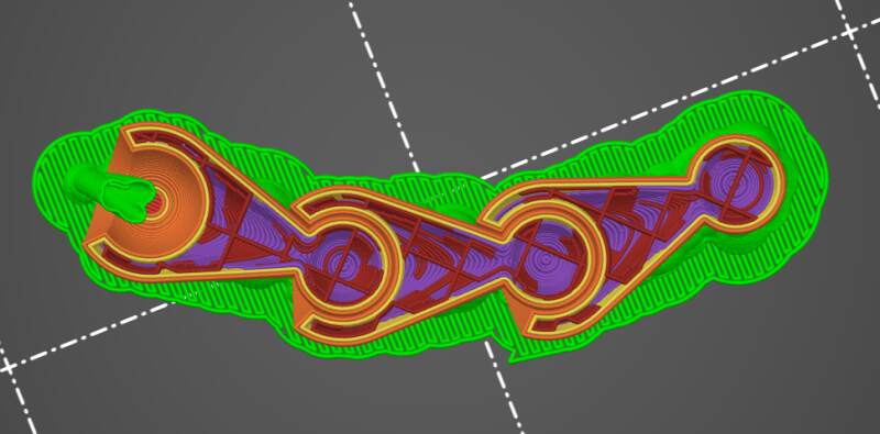
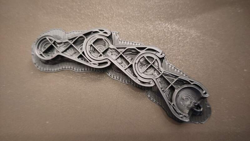
I exported to model as an STL from OpenSCAD and imported it into PrusaSlicer. In the slicer I selected the Original Prusa Mini+ Input Shaper (the printer I have at home) as Printer and ColorFabb allPHA. 1 In the Print settings, I changed the Support material Style to Organic because they are prettier.
Because printing the entire bracelet takes so much time (almost 4 hours!), I decided to print only 3 segments to test the flexibility of the links.
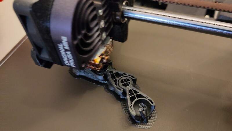
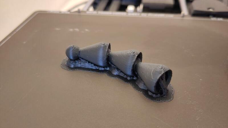
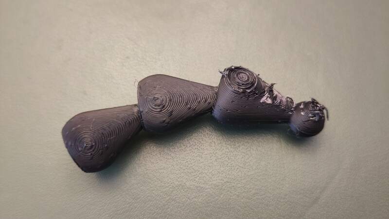
PHA sticks very well to the bed. To remove it, I heated the bed to 90°C and scooped it up with a putty knife.
While cleaning it up for a bit the segments, I found that the segments easily detached. I needed to make a stronger fit.
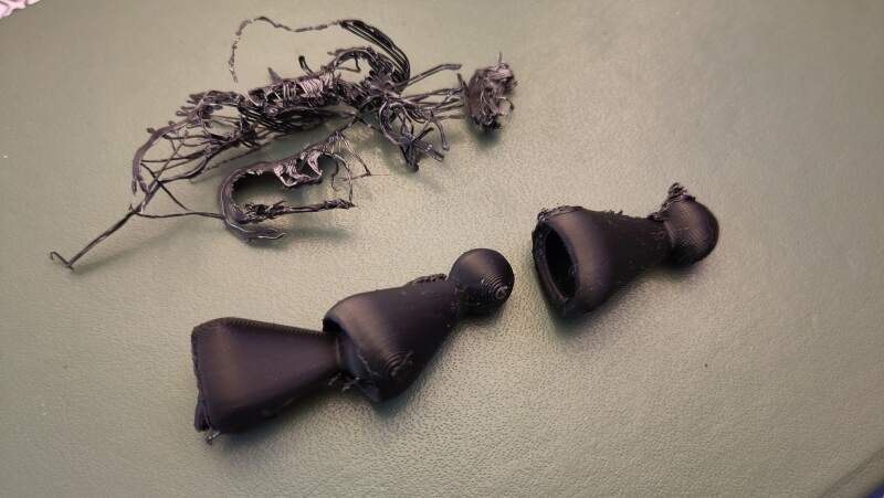
To secure the balls better into the sockets, I made the tolerance (distance between the inner ball and the cavity) and the cone for the cutout smaller. I used the following values:
| variable | value |
|---|---|
tolerance |
0.2 |
cone_r1 |
0 |
cone_r2 |
8 |
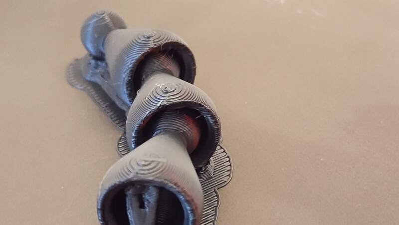
Inspecting the result in PrusaSlicer made me more confident that the segments will not easily separate.
This string of segments did not fall apart. I could not pull it loose.
The video below shows its stiffness.
The joint was a bit stiff, so I wanted to change that to make it more
comfortable. On the first try, it was very loose, so I tried a value
in between 0.3.
| variable | value |
|---|---|
tolerance |
0.3 |
cone_r1 |
0 |
cone_r2 |
8 |
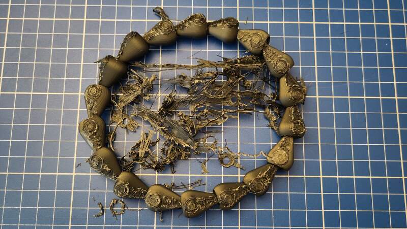
The result using the above parameters is hardly better than the previous print but tolerable. Next, I tried to print the whole bracelet to get a feel for how big it is.
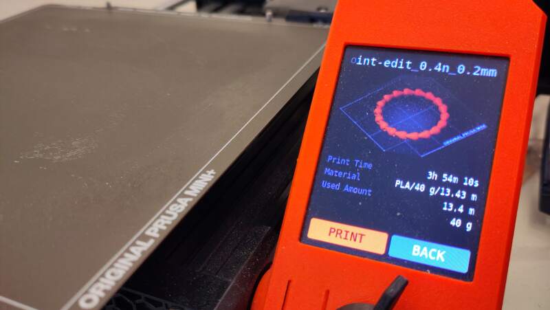
It is very big. To make the segments smaller, I introduced an s
(for scale) parameter in the model to adjust some sizes.
$fn = 200;

s = 1 / 1.2;

inner_r = 5 * s;
outer_r = 7 * s;
spoke_r = inner_r * .2;
spoke_len = inner_r * 4;

tolerance = .4;
cone_r1 = 0;
cone_r2 = 7.5 * s;

module segment() {
  difference() {
    union() {
      sphere(inner_r);
      hull() {
        cylinder(h = spoke_len + 2, r = spoke_r);
        translate([0, 0, spoke_len]) sphere(outer_r);
      }
    }
    translate([0, 0, spoke_len]) {
      sphere(inner_r + tolerance);
      translate([0, 0, -.25 * inner_r]) {
        cylinder(outer_r, cone_r1, cone_r2);
        translate([0, 0, outer_r]) cylinder(10, outer_r);
      }
    }
  }
}

rot = 20;

module go(i) {
  if (i >= 0) {
    segment();
    translate([0, 0, spoke_len]) rotate([rot, 0, 0]) go(i - 1);
  }
}

rotate([0, 90, 0]) go(360 / rot);
Note that the tolerance is not scaled!
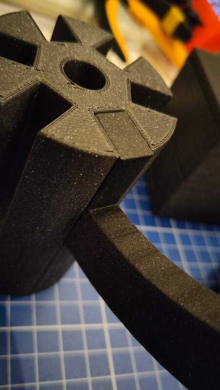
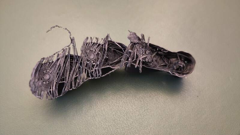
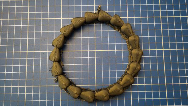
With the above values, the bracelet is still way too big.
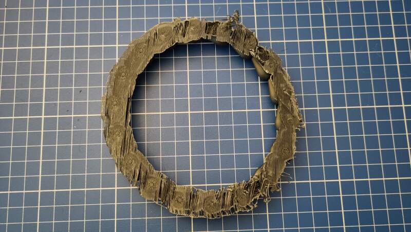
Too big… and the weeding is terrible. It needed to be smaller
still but I felt I could not scale down the joint any further without
it becoming too brittle. I changed spoke_len = inner_r * 3.25 to
make the segments shorter.
For this run, I used the default Snug supports, and the supports came off so easily.
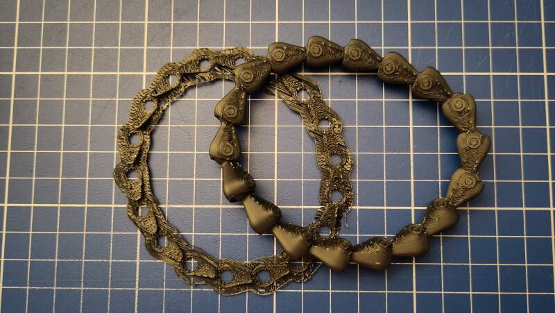
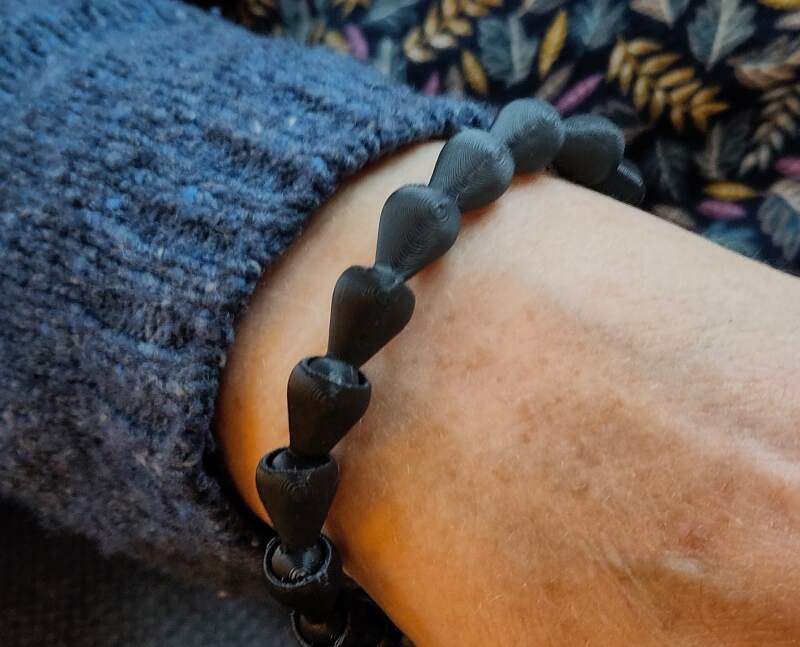
This bracelet is too small for me but I found the perfect hand model: my wife 🖤.
3.3. Scanning an object
The Waag owns a Creality Scan Ferret. Henk showed us how to use it by scanning Heleen's head.
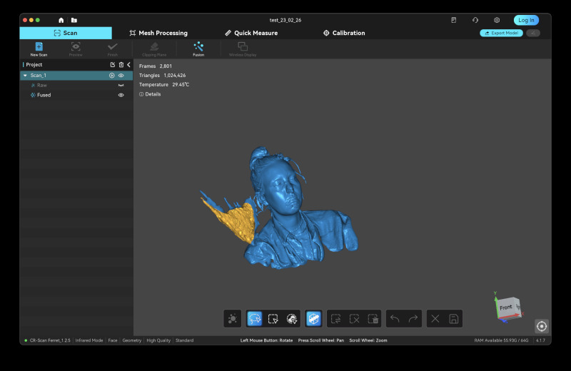
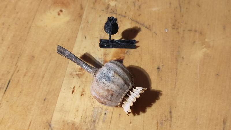
I brought a pine cone and a dried poppy to scan. Unfortunately the companion software only supports MS-Windows or Apple Mac. We tried scanning the pine cone using Heleen's computer but it was very hard to get a proper scan.
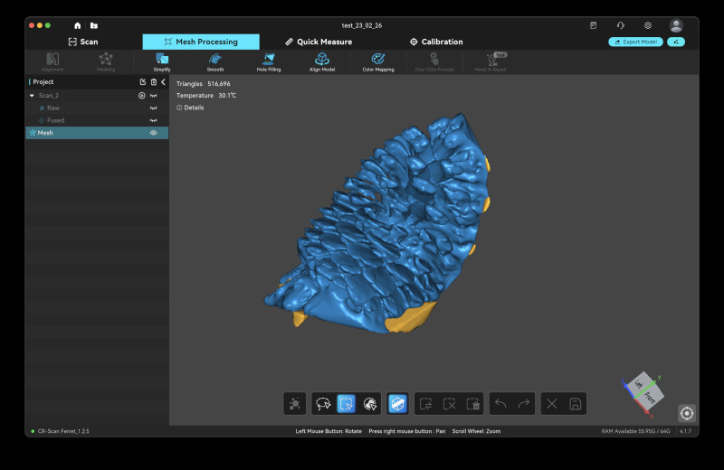
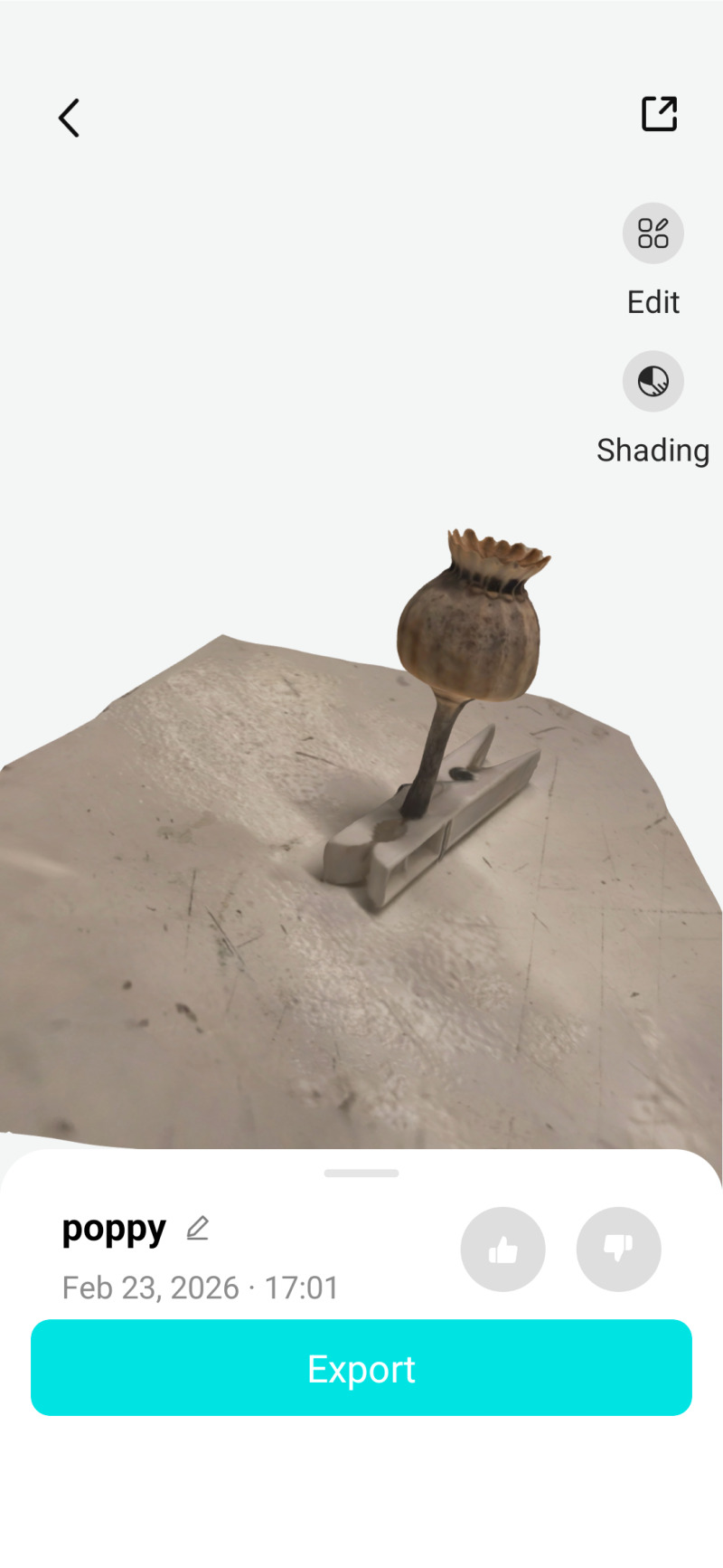
Meanwhile Christian was playing around with Scaniverse on his iPhone and the results were quite good, so I tried that too. Unfortunately, my phone is not supported by Scaniverse (it uses lidar?). Browsing the Google Play store I found Kiri Engine and this does install and work on my phone!
I made a lot of photos using the app (40+) and then it uploaded it to their server.
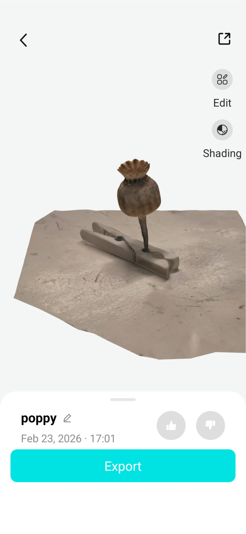
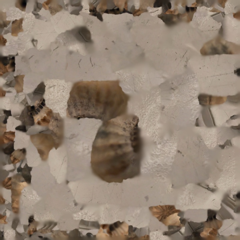
After a couple of minutes I received an email with a link to download a ZIP-file. This file contained:
- 3DModel.jpg (1.3Mb)
- 3DModel.mtl (217 bytes)
- 3DModel.obj (7.9Mb)
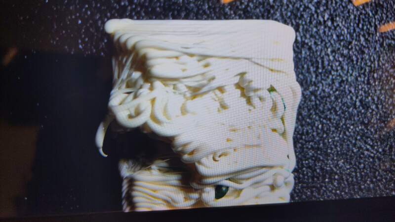
The JPEG-file (see figure 62) is just weird (I think it is an image of the outside to be mapped on the 3D model using the MTL-file) but I managed to import the OBJ-file into PrusaSlicer.
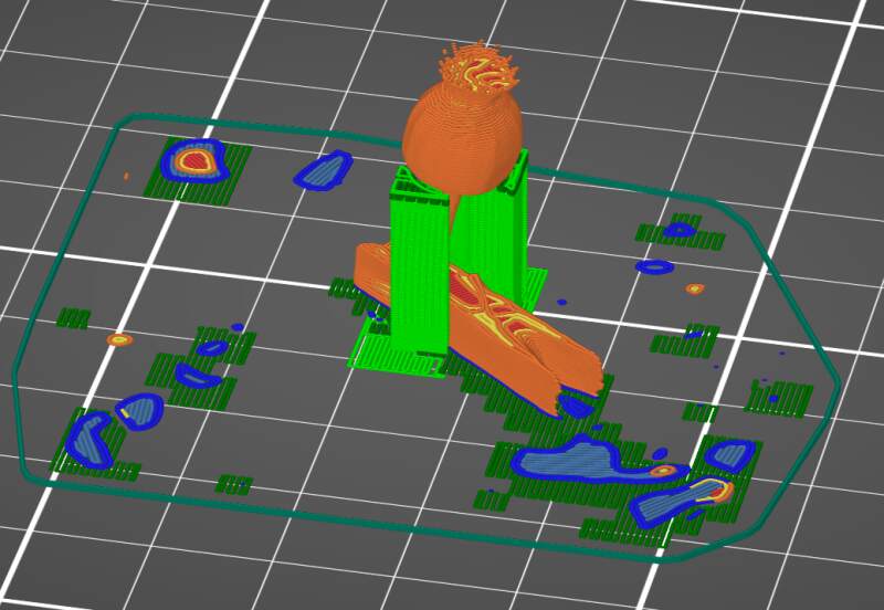
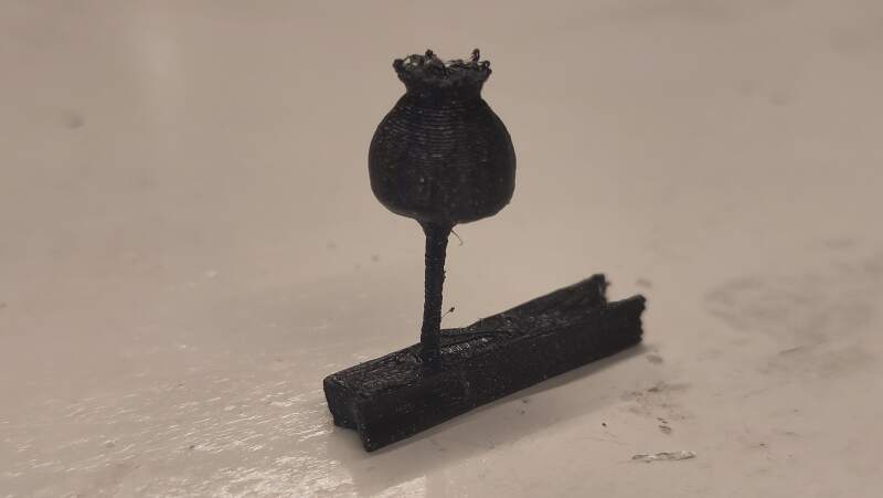
I ignored the artifacts on the first few layers (this print is tiny) and ran it.
4. Reflection
I was very lucky to have a 3D printer at home. I actually bought it to prepare for the Fabacademy last year to force myself into some CAD and machining experience.
4.1. Good
4.2. Bad
5. Source Files
Unfortunately the 3MF-file for the bracelet is 18Mb so I did not include it in the repository.
Footnotes:
I created the ColorFabb allPHA profile myself a while back to reduce warping a bit. You can it here ColorFabb-allPHA.ini.
