System Integration
1. Week Assignments
Design and document the system integration for your final project.
2. Prior Knowledge
Oh my… this is definitely a first for me! It feels like packing for some outlandish expedition and designing all it at the same time…
3. Work!
I composed all the components of my final project into a 3D model using OpenSCAD. Before I did that, I checked that all PCB board sizes were multiples of 5mm to make it easier to fit them onto a frame and into the exterior. using OpenSCAD. Before I did that, I checked all PCB board sizes to be multiples of 5mm to make it easier to fit them onto a frame and into the exterior.
3.1. Overview
This system has the following logical components:
3.1.1. Time display
An array of 30 NeoPixels displaying time in 24-hours notation using 7-segment digits and a colon to separate the hours and minutes.
3.1.2. Automatic time synchronization
Time is kept by the microcontroller's internal clock, which is synchronized from DCF77, a German longwave time signal and standard-frequency radio station.
3.1.3. Audio playback
A microcontroller-driven audio player and speaker will provide wake-up sounds.
3.1.4. Snooze detection
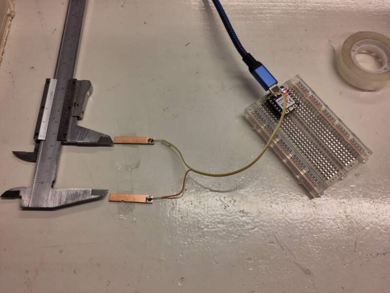
Using step response, a hand can be detected when placed on top of the clock with two embedded copper pads.
3.1.5. Docking station
The clock is battery-powered and will be charged on the docking station. This station also provides a rotary dial to change the wake-up time.
3.1.6. Controller
An RP2350 will control all peripherals and will be programmed to preform all logic functions. These functions include:
- Driving the time display.
- Synchronizing time in regular intervals.
- Playing sounds on wake up time.
- Detecting and applying snooze when in wake-up mode.
- Stopping wake-up mode when placed on docking station.
- Setting and displaying wake-up time from rotary dial.
3.2. Bill of Materials
Below is a list of components to build this clock.
| Amount | Description | Price | Sum | Function |
|---|---|---|---|---|
| 1 | SEEED STUDIO XIAO | 5.75 | 5.75 | Main / RP2350 |
| 1 | DCF77 | 2.69 | 2.69 | Main / Radio Clock Receiver |
| 1 | DFPLAYER - A MINI MP3 PLAYER | 5.01 | 5.01 | Main / Audio source |
| 1 | 8Gb TF (Mini SD) | 12.40 | 12.40 | Main / Audio storage |
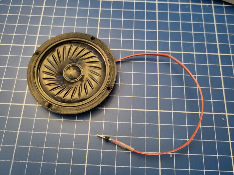
| 1 | Speaker | 2.00 | 2.00 | Main / Audio output |
| 1 | RES 0 OHM JUMPER 1/4W 1206 | 0.10 | 0.10 | Main / Electrical |
| 1 | RES 1K OHM 1% 1/4W 1206 | 0.10 | 0.10 | Main / Electrical |
| 1 | Makerfocus 3.7V 3000mAh Lithium | 15.00 | 15.00 | Main / Battery |
| 10 | M3*8 nuts and bolts | 0.10 | 1.00 | Main |
| 30 | ADDRESS LED SERIAL RGB | 0.25 | 7.50 | Display / Light |
| 4 | CAP CER 1UF 50V X7R 1206 | 0.25 | 1.00 | Display / Electrical |
| 1 | KY-040 Rotary Encoder | 2.44 | 2.44 | Docking / Time selection |
| 1 | CONN SPRING MOD MALE 6POS SMD | 1.95 | 1.95 | Docking / Connector dock |
| 1 | CONN SPRING MOD FEMALE 6POS SMD | 1.92 | 1.92 | Docking / Connector clock |
| 4 | Magnets | 0.30 | 1.20 | Docking / Placement |
| 1 | USB-C PD Trigger Board | 1.67 | 1.67 | Docking / Power |
| 1 | 12mm plywood | 20.00 | 20.00 | Housing and dock |
| 2 | 3mm clear acrylic | 5.00 | 10.00 | Housing |
| 4 | M5 nuts and bolts | 0.10 | 0.40 | Housing |
| Total ex. VAT | €92.13 |
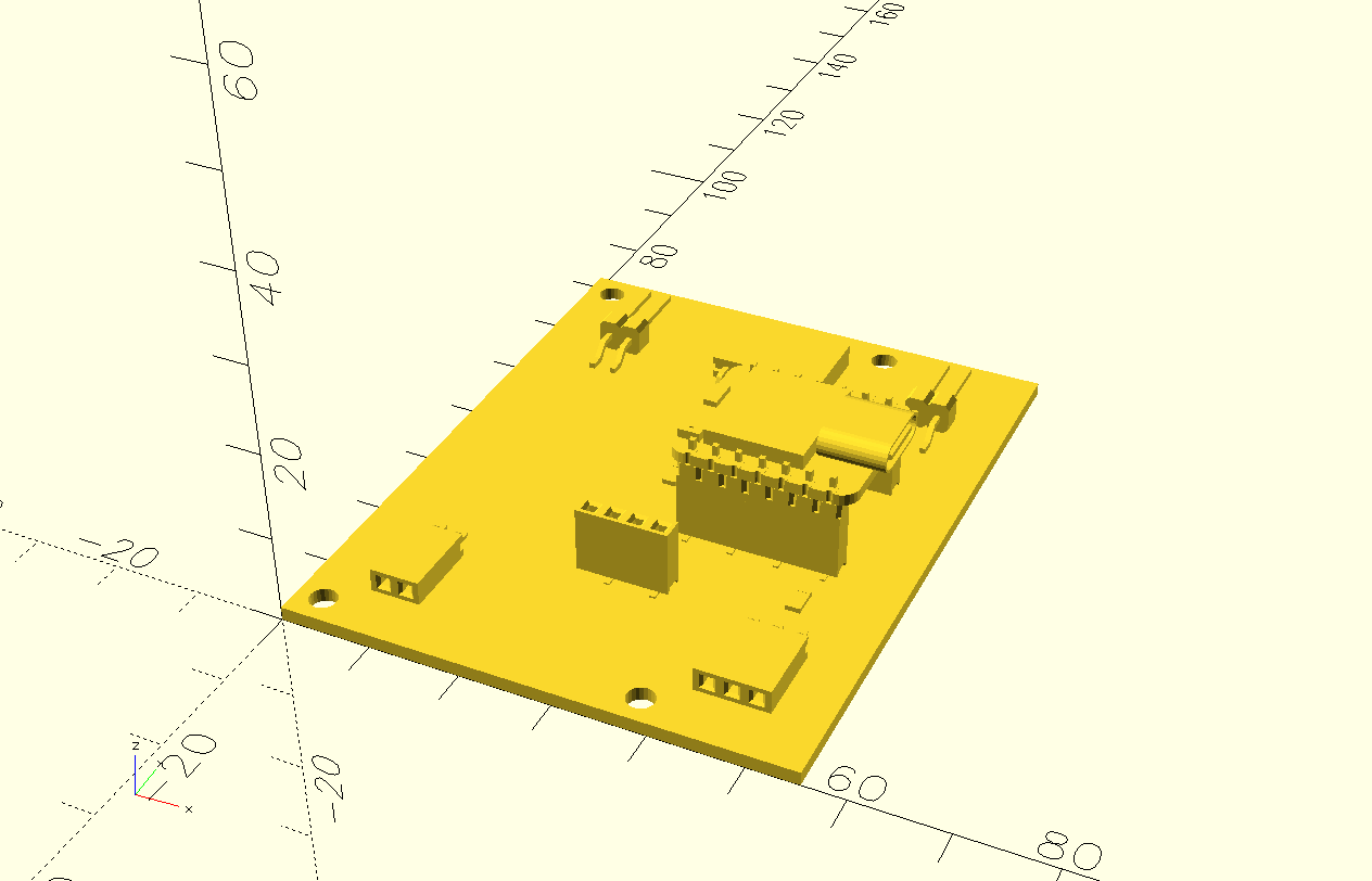
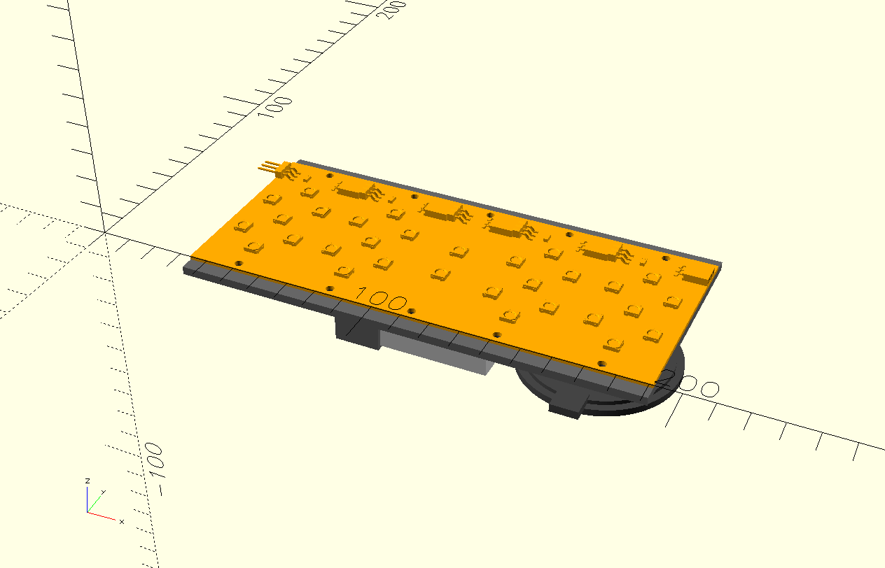
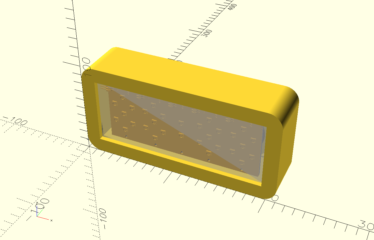
3.3. PCBs
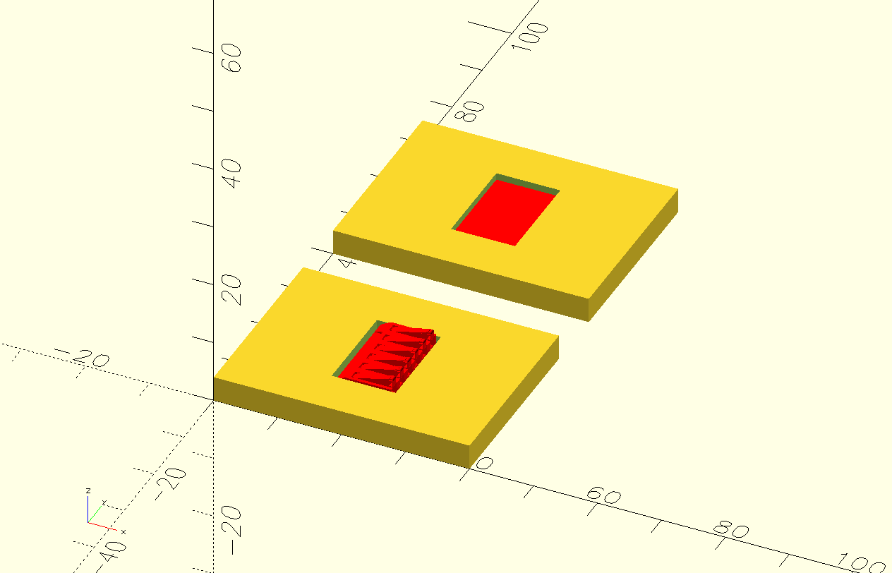
I exported all PCBs to STL models and imported them into OpenSCAD.
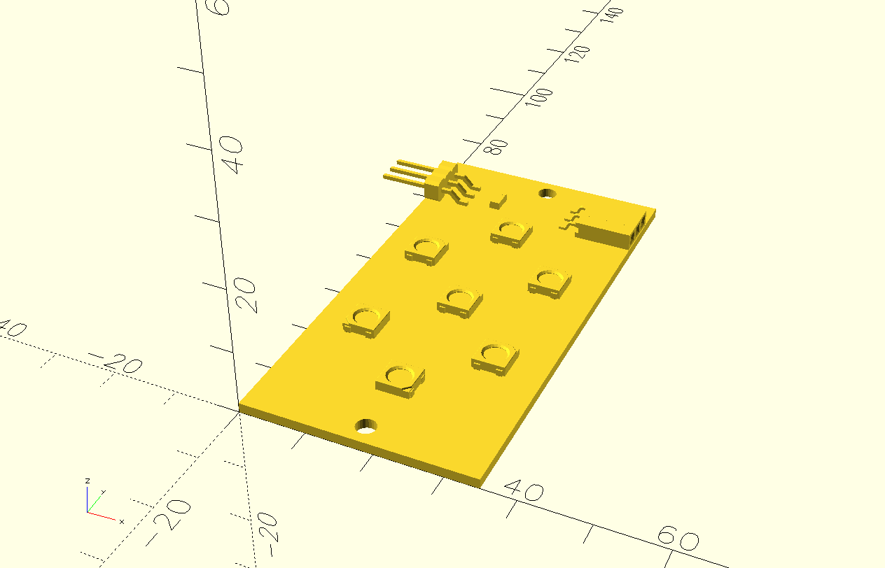
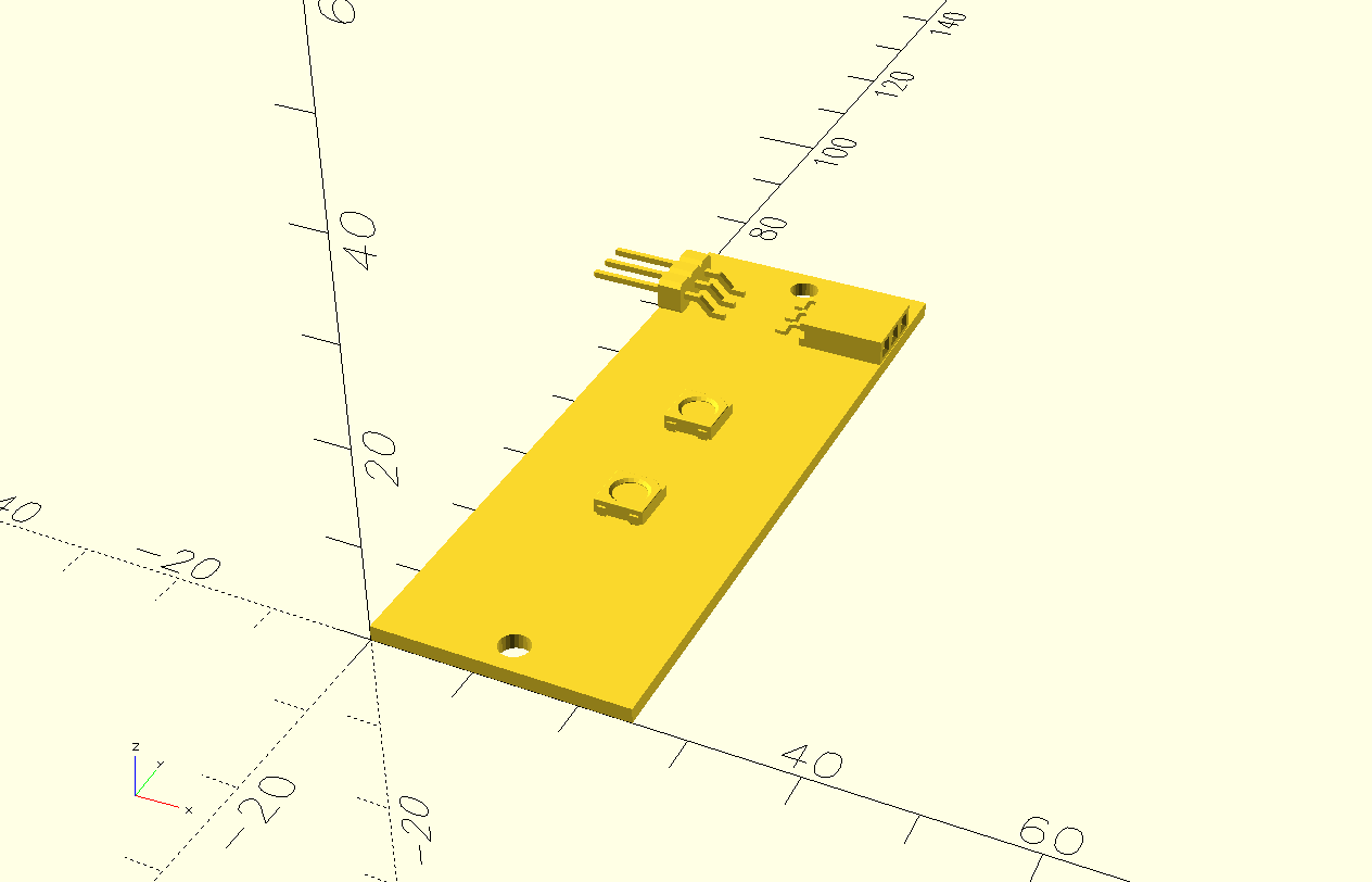
The above are connected as in the picture below.
Note the holes on the top and bottom edges. They'll be used to mount them on a frame.
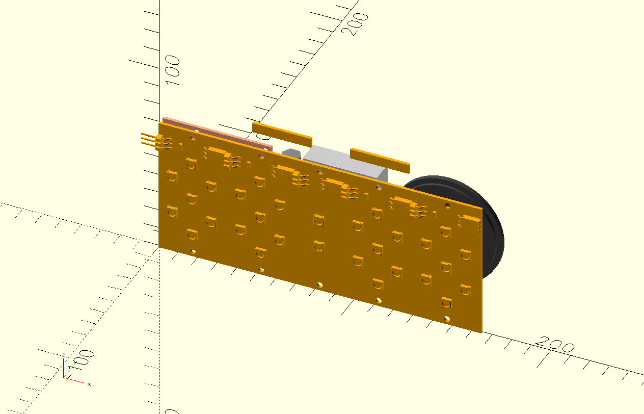
The main board goes on the back of the display, so the holes in this board align with the holes in the display. Note that the board is incomplete; I do not have 3D models for the DFPLAYER and DCF77 boards.
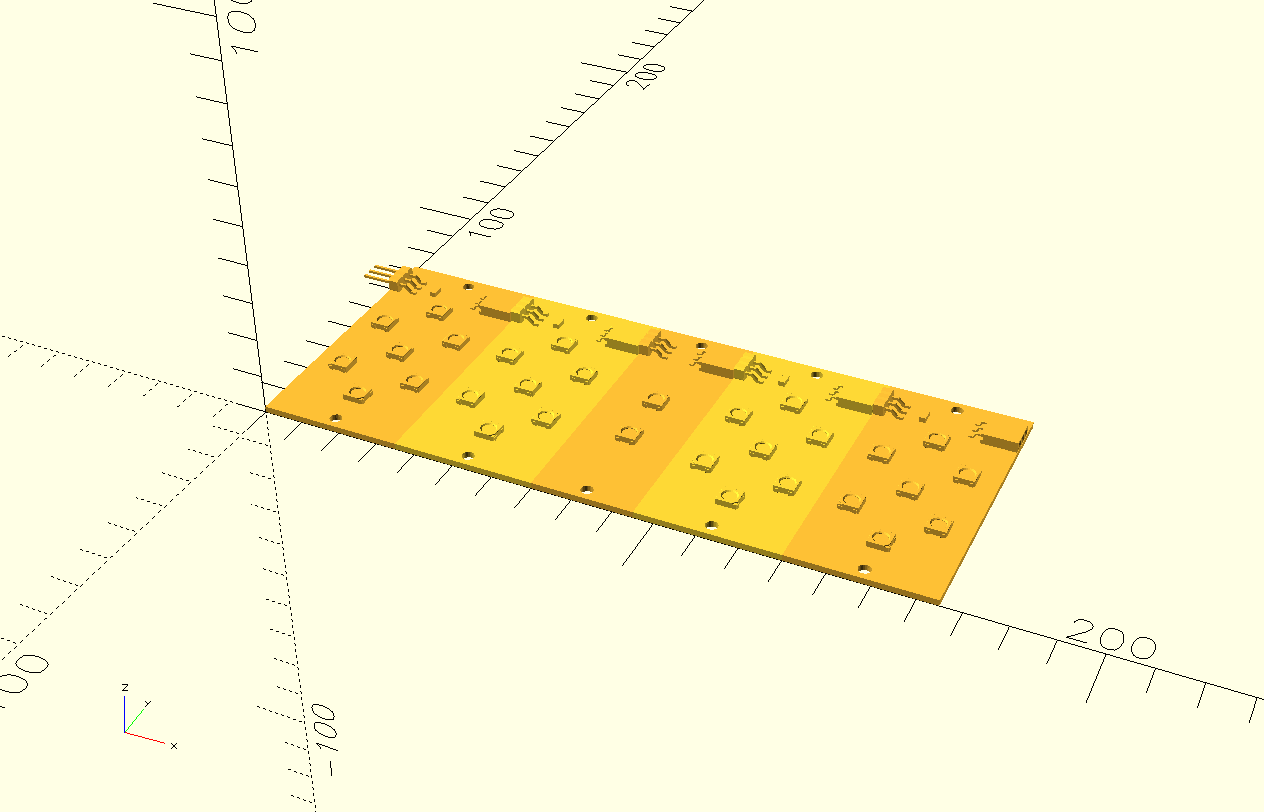
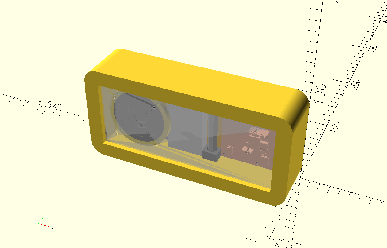
3.4. Electrical components
Apart from the PCBs, there are some more components: a battery, a DCF77 antenna, a speaker and the snooze copper pads. I arranged them as follows.
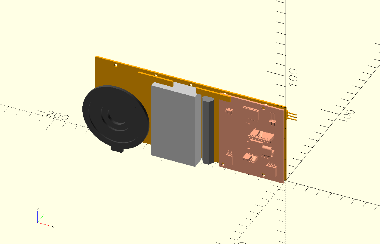
Note the two floating bits on top, they are the small pieces of copper to detect a hand on top of the clock using step response. They stick out above the rest of the components because they will be embedded in the housing.
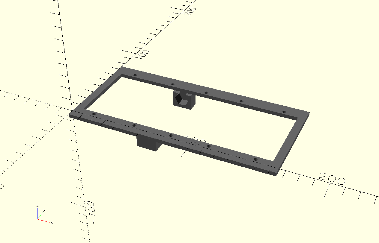
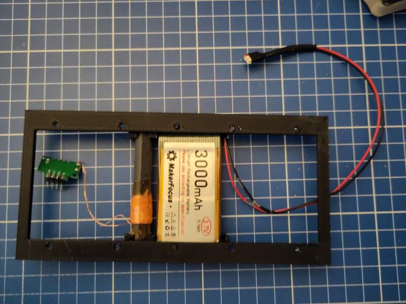
I created a frame (to be 3D printed) to mount the components on.
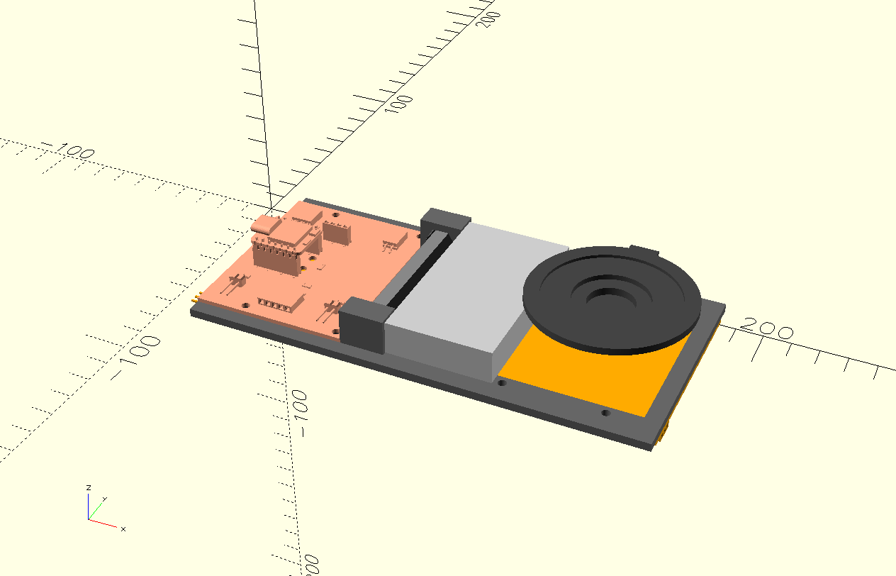
Note that the speaker is not attached to the frame. It will vibrate and should be attached to the housing.
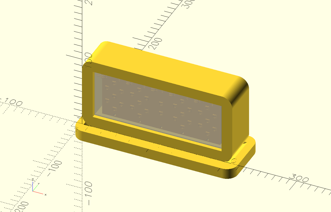
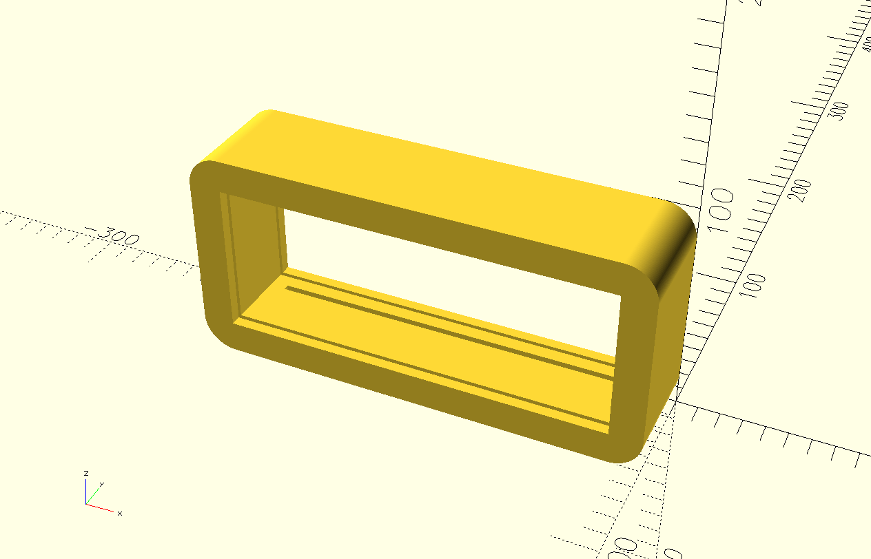
3.5. Housing
For the outside, I decided on a basic box with rounded sides. The clock will be in the center with transparent acrylic on the outsides, allowing one to see the internals. I am planning on CNC milling these "rings" and providing slits in the edges to lock in the components frame and acrylic windows.
3.5.1. Stacking and locking
The position of the slits will depend on the thickness of the wood to be milled because it is not possible to make a horizontal cut.
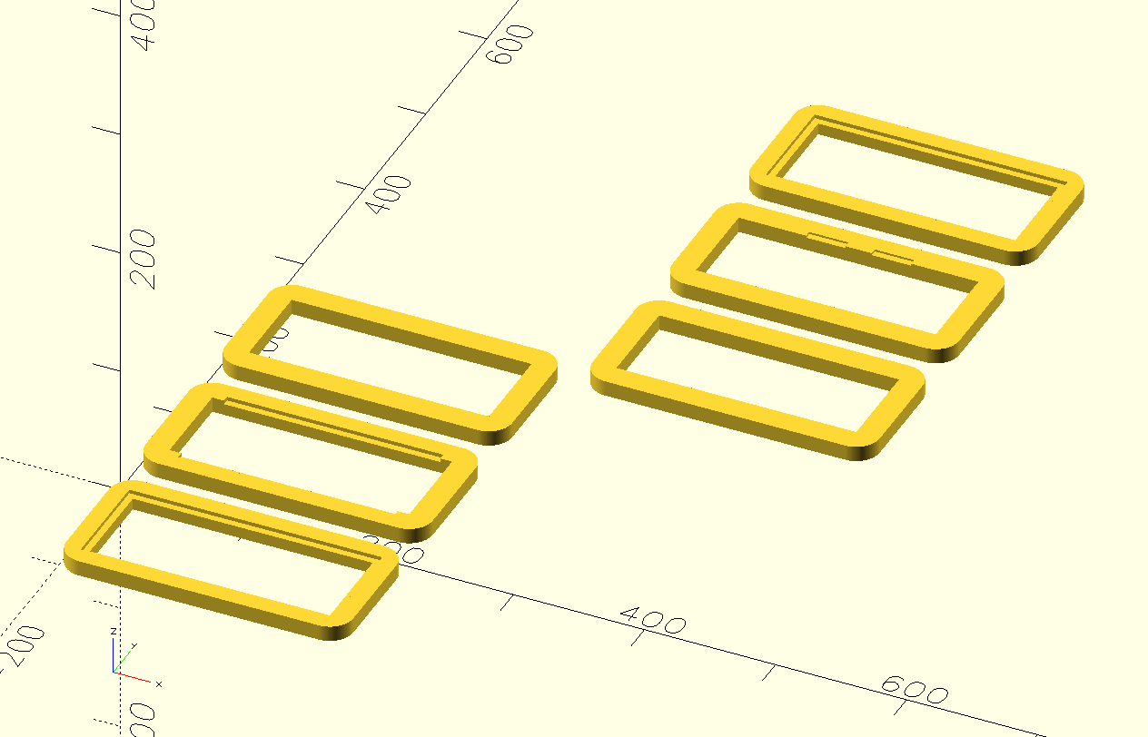
Note that in the picture above, that some of the slices are flipped with the pockets / slits to be milled on top.
3.5.1.1. TODO locking with M5 bolts
The corners of the housing need a hole all the way through to allow locking the slices together.
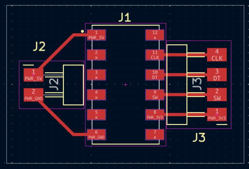
3.5.2. Connector
I designed a basic PCB for this (both sides have a similar footprint), and made some sketches for 3D printable components to hide the wires and attach it to the housing and docking station.
3.5.2.1. TODO position and wire access through housing
3.5.2.2. TODO 3D model for holder with magnets and screw holes to fix to wood
3.5.3. Snooze
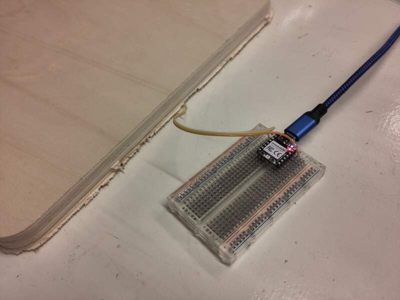
To detect a snooze action, the clock needs two metal plates to perform step response detection of a hand. Small copper pads will easily detect a hand through a thick layer of wood.
3.5.4. USB access to microcontroller
To make updating the software easier, it would be really nice to have access to the USB port on the microcontroller without taking the clock apart. There are plenty of USB-C extension options. I ordered some variants to get a feel for them.
3.5.4.1. TODO add access through housing when extension arrives
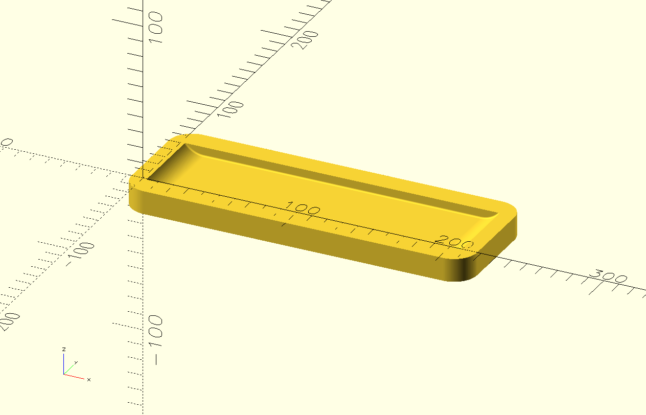
3.6. Dock
The base docking station will look something like below.
3.6.1. Connector
See also 3.5.2.
3.6.2. TODO Rotary Encoder
A big 3D printed knob on a rotary encoder. I do not yet know how to attach this properly to the dock. The dock will probably have two layers of wood to allow placing the components in a milled pocket on the bottom layer.
3.7. Other Loose Ends
- Wiring (pretty ribbon wire with pin header / connectors + heat shrink)
- Power adapter (USB-C or some other 5V adapter)
- And probably lots more…
4. Reflection
The final project stress is rising! This has been a grueling week because there's so much work to do for this assignment. I underestimated the extra "hardware" dimension of this project; there are so many details I want to get right before continuing.
4.1. Good
4.2. Bad
5. Source Files
KiCad:
OpenSCAD:
