Embedded Programming
1. Week Assignments
Group Assignment:
- Demonstrate and compare the toolchains and development workflows for available embedded architectures
- Document your work to the group work page and reflect on your individual page what you learned
Individual assignment:
- Browse through the datasheet for a microcontroller
- Write and test a program for an embedded system using a microcontroller to interact (with local input &/or output devices) and communicate (with remote wired or wireless connections)
2. Prior Knowledge
During the week I discovered I had more prior knowledge than I expected. Here are a few things that came to mind:
- MOS 6510 assembly on the Commodore 64
- M68k assembly and C on the Atari 520ST
- CircuitPython on Adafruit MACROPAD RP2040
- Keyboard firmware changes using QMK
- Playing around with Arduino 10 years ago 8x8 LED beating heart
3. Work!
I browsed the RP2040 datasheet and here is a list of random facts I learned about this micro controller:
- It has a Arm Cortex-M0+ processor.
- It has full USB 2.0 onboard at "full speed".
- There is memory-mapped I/O like on the MOS6510 and M68k; it is called the Single-cycle IO block (SIO). Nostalgic!
- It supports protected memory so it can run a proper operating system.
- XIP (Execute In Place) memory can be used to run code directly from Flash, instead of needing to load it into SRAM.
- It can be put in a sleep state using the WFE (Wait For Event) and WFI (Wait For Interrupt) instructions and still receive interrupts.
- The second core goes to sleep on startup with Wait For Event with deep sleep (what is deep sleep?) is enabled.
- The boot ROM contains libraries for floating-point operations, memory copying and bit operations.
- The RP2040 does not have an FPU (Floating Point Unit), so all floating-point operations are "soft" and slow. And you can read the code here!
- There's a picotool to manipulate (
info,save,erase, etc.) the RP2040 when it is in BOOTSEL mode. - It needs power on multiple pins to run.
- It has a lot of clocks which can be manipulated to preserve power.
- There are two sleep states: SLEEP which can wake up from an interrupt or event and DORMANT were are clocks are stopped and it requires a GPIO or RTC event to wake up.
- Parts of the memory can be powered down too!
- The clock (Ring Oscillator ROSC) has a varying speed due to temparature and other factors. It can be turned off and replace by an external Crystal Oscillator (XOSC).
- A connected XOSC (through XIN and XOUT pins) is not automatically started and when started needs to stabilize before it is up to speed.
- It has 4 GPIO pins which can be used for analog reads (ADC).
- The 30 user usable GPIO pins can all do PWN (Pulse Width Modulation) but there are 8 PWM slices (think this means you can only do 8 different configurations at the same time).
- These user pins can also be connected to Programmable IO blocks (PIO).
- There 2 PIO blocks with 4 state machines each.
- A PIO state machine can drive up to 32 GPIOs.
- It has two I²C controllers.
3.1. Arduino IDE
Our guest instructor Leo gave a nice presentation about microcontroller basics, covering programmers and bootloaders, loops and interrupts, pulse width modulation and programmable IO. After that he pulled out Arduino UNO kits and we started blinking lights.
To get the Arduino IDE to work on my Guix system was a bit of a hassle. There are no Arduino packages for Guix, but I can also install Nix packages.
nix-env -i arduino-ide
Unfortunately compiling code in the IDE resulted in an error message.
In file included from /home/me/.guix-profile/include/c++/stdlib.h:36:0,
                 from /home/me/.arduino15/packages/arduino/hardware/avr/1.8.7/cores/arduino/Arduino.h:23,
                 from /home/me/.cache/arduino/sketches/30DFEAE616D41367A3EB0E1516DBA631/sketch/Blink.ino.cpp:1:
/home/me/.guix-profile/include/c++/cstdlib:46:10: fatal error: bits/c++config.h: No such file or directory
 #include <bits/c++config.h>
          ^~~~~~~~~~~~~~~~~~
compilation terminated.
exit status 1

Compilation error: exit status 1
It seems the IDE tries to include my local header files (I have the gcc-toolchain installed) which do not apply for the cross compiler (a compiler which does not emit native code but code for another platform). Guix is very environment variable having so before starting Arduino IDE I needed to unset the C compiler related variables. Like this it works:
# Avoid loading the local header files
unset C_INCLUDE_PATH CPLUS_INCLUDE_PATH OBJC_INCLUDE_PATH OBJCPLUS_INCLUDE_PATH
arduino-ide
I hooked up the UNO board to my laptop using USB. Then I selected the
UNO in the IDE via Tools -> Board and the Tools -> Port was
magically set to /dev/ttyACM0. I opened the Blink example from File
-> Examples -> 01.Basics, hit the Upload button in the toolbar
and it just worked.
Changing the code was a bit of a hassle because the file was read-only, so I needed to do File -> Save as first. After that I changed the blink speed and even dimmed it by making the delay after turning the LED on 2 milliseconds and the delay after turning it off 20 milliseconds.
// the setup function runs once when you press reset or power the board
void setup() {
  // initialize digital pin LED_BUILTIN as an output.
  pinMode(LED_BUILTIN, OUTPUT);
}

// the loop function runs over and over again forever
void loop() {
  digitalWrite(LED_BUILTIN, HIGH);  // turn the LED on (HIGH is the voltage level)
  delay(2);                         // wait for a second
  digitalWrite(LED_BUILTIN, LOW);   // turn the LED off by making the voltage LOW
  delay(20);                        // wait for a second
}
With the above loop the LED no longer visibly blinks but was dimmed. Henk joked Chickens still see it blink and go insane. This method is called: PWM (Pulse Width Modulation).
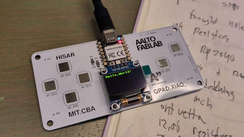
3.2. QPAD XIAO
Henk got us QPAD XIAO boards, XIAO modules and OLED displays to play with this week.
| # | Material |
| 1 | QPAD-xiao board |
| 1 | Seeed XIAO PR2040 |
| 1 | OLED module SSD1306 I²C |
| 2 | 10k resistor 1206 |
3.2.1. Build
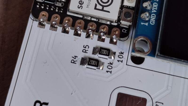
Following Henk's example and the instructions at gitlab / Quentin Bolsee / qpad-xiao (from the QR-code on the back of the board), I soldered on the resistors, XIAO and the OLED modules (ours came with headers preinstalled, Henk got them here).
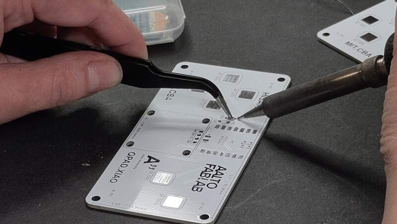
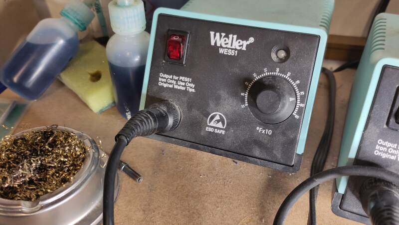
Those 1206 resistors were quite small (0.12 inches = 3.048mm long and 0.06 inches = 1.524mm wide), but soldering them was easier than I expected. The solder iron temperature was set to 78 (see figure 3) but it was unclear what this actually means (my first guess: 378°C).
After a hint from Henk, I noticed the °Fx10 sign on the power
station. Apparently it was set to 780°F which is 415°C, which is
quite high. The recommended temperature for lead free soldering is
380°C (see also Lead-Free Soldering).
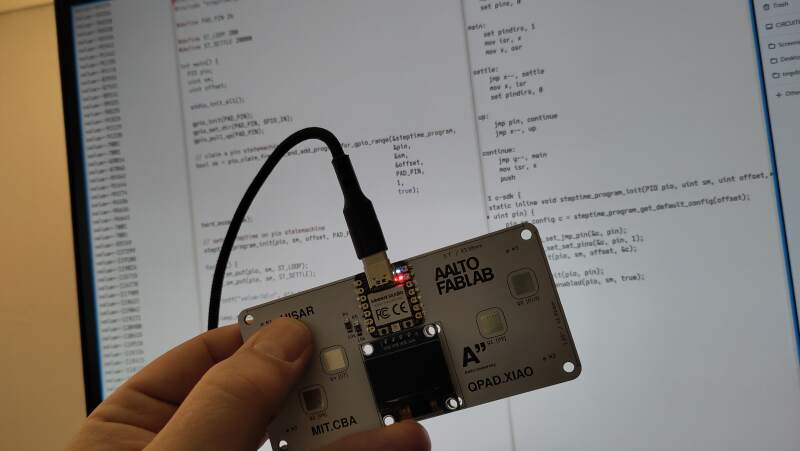
After connecting the USB to a power source (my laptop) the NeoPixel started blinking red, green and blue so at least the XIAO survived the soldering!
3.2.2. MicroPython
Next we were instructed to install MicroPython on the XIAO to allow programming it in Python. The RP2040 comes with a bootloader which allows it to startup in "boot mode" (named BOOTSEL in the documentation) when powering up with the "B" button pressed, it presents itself as a USB drive named "RPI-RP2" to a computer. It contains two files:
INDEX.HTM
Opening this in a web browser redirects to Raspberry Pi Documentation.
INFO_UF2.TXT
Contains information about the board and the bootloader.
UF2 Bootloader v3.0
Model: Raspberry Pi RP2
Board-ID: RPI-RP2
This drive accepts files with the extension .uf2 and installs them
as the main program when copied in, and then reboot thes board.
I later found out that pressing "B" and then "R" (reset) also resets it into BOOTSEL mode.
It was suggested to use Thonny to install MicroPython, but I decided to just install the UF2-file myself. Looking at the Seeed Studio documentation for this board (which uses Thonny) I found that I need the standard Raspberry Pi PICO installation. I downloaded it and copied it to the drive.
After rebooting, the RGB blinking was gone and the /dev/ttyACM0
showed up again in the kernel messages.
[145640.984952] usb 1-1: new full-speed USB device number 43 using xhci_hcd
[145641.123057] usb 1-1: New USB device found, idVendor=2e8a, idProduct=0005, bcdDevice= 1.00
[145641.123076] usb 1-1: New USB device strings: Mfr=1, Product=2, SerialNumber=3
[145641.123082] usb 1-1: Product: Board in FS mode
[145641.123087] usb 1-1: Manufacturer: MicroPython
[145641.123091] usb 1-1: SerialNumber: 4250304638313309
[145641.126853] cdc_acm 1-1:1.0: ttyACM0: USB ACM device
I tried connecting to this serial port in Emacs with M-x serial-term
(with the suggested baud rate of 9600) and got a Python REPL
(Read-Eval-Print Loop). I worked!
MicroPython v1.27.0 on 2025-12-09; Raspberry Pi Pico with RP2040
Type "help()" for more information.
>>> help()
Welcome to MicroPython!

For online docs please visit http://docs.micropython.org/

For access to the hardware use the 'machine' module.  RP2 specific commands
are in the 'rp2' module.

Quick overview of some objects:
  machine.Pin(pin) -- get a pin, eg machine.Pin(0)
  machine.Pin(pin, m, [p]) -- get a pin and configure it for IO mode m, pull mode p
    methods: init(..), value([v]), high(), low(), irq(handler)
  machine.ADC(pin) -- make an analog object from a pin
    methods: read_u16()
  machine.PWM(pin) -- make a PWM object from a pin
    methods: deinit(), freq([f]), duty_u16([d]), duty_ns([d])
  machine.I2C(id) -- create an I2C object (id=0,1)
    methods: readfrom(addr, buf, stop=True), writeto(addr, buf, stop=True)
             readfrom_mem(addr, memaddr, arg), writeto_mem(addr, memaddr, arg)
  machine.SPI(id, baudrate=1000000) -- create an SPI object (id=0,1)
    methods: read(nbytes, write=0x00), write(buf), write_readinto(wr_buf, rd_buf)
  machine.Timer(freq, callback) -- create a software timer object
    eg: machine.Timer(freq=1, callback=lambda t:print(t))

Pins are numbered 0-29, and 26-29 have ADC capabilities
Pin IO modes are: Pin.IN, Pin.OUT, Pin.ALT
Pin pull modes are: Pin.PULL_UP, Pin.PULL_DOWN

Useful control commands:
  CTRL-C -- interrupt a running program
  CTRL-D -- on a blank line, do a soft reset of the board
  CTRL-E -- on a blank line, enter paste mode

For further help on a specific object, type help(obj)
For a list of available modules, type help('modules')
>>>
Next, I tried to toggle the LED pin. I found the pin number in the XIAO RP2040 pin map on the Seeed Studio site.
| XIAO Pin | Function | Chip Pin | Description |
| 5V | VBUS | Power Input/Output | |
| GND | |||
| 3V3 | 3V3_OUT | Power Output | |
| D0 | Analog | P26 | GPIO, ADC |
| D1 | Analog | P27 | GPIO, ADC |
| D2 | Analog | P28 | GPIO, ADC |
| D3 | Analog | P29 | GPIO, ADC |
| D4 | SDA | P6 | GPIO, I2C Data |
| D5 | SCL | P7 | GPIO, I2C Clock |
| D6 | TX | P0 | GPIO, UART Transmit |
| D7 | RX,CSn | P1 | GPIO, UART Receive,CSn |
| D8 | SCK | P2 | GPIO, SPI Clock |
| D9 | MISO | P4 | GPIO, SPI Data |
| D10 | MOSI | P3 | GPIO, SPI Data |
| Reset | RUN | RUN | |
| Boot | RP2040_BOOT | Enter Boot Mode | |
| CHARGE_LED | VCC_3V3 | CHG-LED_Red | |
| RGB LED | NEOPIX | RGB LED | |
| USER_LED_R | IO17_RGB-R | User-controlled red RGB LED pin | |
| USER_LED_B | IO25_RGB-B | User-controlled blue RGB LED pin | |
| USER_LED_G | IO16_RGB-G | User-controlled green RGB LED pin |
In the Raspberry Pi Pico Pinout there's also a LED on pin 25, but apparently at XIAO they decided to combine it with pin 16 and 17 into a RGB LED.
>>> from machine import Pin
>>> led = Pin(25, Pin.OUT)
>>> led.value(1)
>>> led.value(0)
Interestingly, turning the pin "on" (1) makes the LED glow yellow (blue is turned "off") and turning the pin "off" (0) makes it white.
3.2.2.1. Getting code on board
Quentin's repo also comes with a lot of MicroPython example code to play with the OLED display, NeoPixel and the touch pads. MicroPython includes many standard libraries but no specialized libraries to drive the OLED display or the NeoPixel. But how to get code on the board without Thonny?
Reading the MicroPython documentation I found mpremote, which is not available in Guix 1 but installable through Nix.
nix-env -i mpremote
To get the hello_oled.py to work (I wanted a "hello, world!" message) I did the following:
# install oled library
wget https://gitlab.cba.mit.edu/quentinbolsee/qpad-xiao/-/raw/main/code/Micropython/libraries/ssd1306.py
mpremote cp ssd1306.py :ssd1306.py

# get and run
wget https://gitlab.cba.mit.edu/quentinbolsee/qpad-xiao/-/raw/main/code/Micropython/hello_oled.py
mpremote run hello_oled.py
Unplugging and plugging it in again left the display black. On the
Reset and Boot Sequence page of the MicroPython documentation I
discovered that copying a Python file named main.py to the device
makes it run that script on start up.
mpremote cp hello_oled.py :main.py
Now it shows "Hello,World!" after a power cycle.
For experimentation I combined Quentin's hello_oled.py with the blink script on the Seeed Studio getting started page.
from ssd1306 import SSD1306_I2C
from machine import Pin, I2C, Timer
from time import sleep

i2c = I2C(1, scl=Pin(7), sda=Pin(6), freq=200000)
oled = SSD1306_I2C(128, 64, i2c)

oled.fill(0)
oled.text("Hello,World!",0,0)
oled.show()

ledR = Pin(17, Pin.OUT)
ledB = Pin(25, Pin.OUT)
ledG = Pin(16, Pin.OUT)
Counter = 0

def fun(tim):
    global Counter
    Counter = Counter + 1
    ledR.value(Counter % 2)
    ledB.value(Counter % 2)
    ledG.value(Counter % 2)

tim = Timer(-1)
tim.init(period=1000, mode=Timer.PERIODIC, callback=fun)
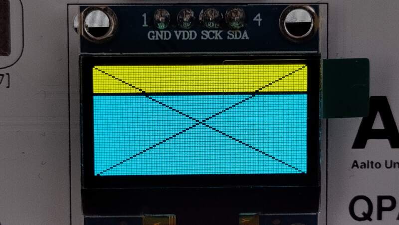
It was interesting to see the display does not update after a reset of the RP2040, but it does reset after a power cycle.
Also interesting: filling all the pixels and putting a cross over it revealed the pixel color and layout are rather strange (see figure 6). It seems this component was created for a special purpose.
from ssd1306 import SSD1306_I2C
from machine import Pin, I2C, Timer
from time import sleep

i2c = I2C(1, scl=Pin(7), sda=Pin(6), freq=200000)
oled = SSD1306_I2C(128, 64, i2c)

# Copied from: https://gitlab.cba.mit.edu/quentinbolsee/qpad-xiao/-/blob/main/code/Micropython/hello_qed.py
def drawLine(x0, y0, x1, y1, c=1):
  dx = abs(x1 - x0)
  sx = 1 if x0 < x1 else -1
  dy = -abs(y1 - y0)
  sy = 1 if y0 < y1 else -1
  err = dx + dy
  while True:
      if 0 <= x0 < 128 and 0 <= y0 < 64:
          oled.pixel(x0, y0, c)
      if x0 == x1 and y0 == y1:
          break
      e2 = err * 2
      if e2 >= dy:
          err += dy
          x0 += sx
      if e2 <= dx:
          err += dx
          y0 += sy

oled.fill(1)
drawLine(0, 0, 128, 64, 0)
drawLine(0, 64, 128, 0, 0)
oled.show()
I borrowed the Bresenham implementation from Quentin because my OLED board does not have a function to draw a line.
Finally, I played with a couple of the samples on Quentin's page to see if the NeoPixel and touch pads worked – and they did.
3.2.3. Pico SDK
Reading through the RP2040 datasheet I found out about the Pico SDK and decided I want to try it out. It is very well documented!
Following the instructions at Pico SDK, I did the following to create
blink firmware but now written in C. First I needed to install the
required packages to use the SDK. Since I am using Guix, I can't use
the example apt install command but need to create a Guix manifest.
(use-package-modules cmake
                     commencement
                     embedded
                     nss
                     python
                     version-control)

(packages->manifest
 (list cmake
       gcc-toolchain
       git
       gnu-make
       python
       nss-certs
       (make-arm-none-eabi-nano-toolchain-12.3.rel1)))
I found the above make-arm-none-eabi-nano-toolchain method by
browsing the Guix source code in the embedded packages file. Finally
something that works without depending on Nix or containers! Note:
the above is the full list of packages needed to build a basic C
program using the Pico SDK and can be used completely containerized
(with guix shell -CPN).
Next, I pulled in the SDK as a git submodule.
git submodule add https://github.com/raspberrypi/pico-sdk

# the SDK also has submodules
(cd pico-sdk; git submodule update --init)
This SDK is based on CMake. I worked with CMake before but without really understanding it.
I downloaded the blink_simple.c file from the Pico Examples repository and followed the SDK instructions to set up a CMakeLists.txt file following the SDK instructions.
cmake_minimum_required(VERSION 3.13...3.27)

# initialize pico-sdk from submodule
# note: this must happen before project()
include(../pico-sdk/pico_sdk_init.cmake)

project(my_project)

# initialize the Raspberry Pi Pico SDK
pico_sdk_init()

# rest of your project
add_executable(blink_simple
    blink_simple.c
)

# Add pico_stdlib library which aggregates commonly used features
target_link_libraries(blink_simple pico_stdlib)

# create map/bin/hex/uf2 file in addition to ELF.
pico_add_extra_outputs(blink_simple)
Finally I could start building firmware – well, setup the build
directory for building.
cmake -S . -B build -DPICO_BOARD=seeed_xiao_rp2040
This generated a lot of output but it was successful. It did warn about not finding picotool but will build it from source, which is fine.
The PICO_BOARD parameter ensures the seeed_xiao_rp2040.h is
automatically included for the correct pin numbers, etc.
Interestingly, the XIAO header file defines
PICO_DEFAULT_LED_PIN_INVERTED which, I think, relates to my earlier
discovery that the LED is turn on by setting the pin to low.
Now I could start building the firmware!
cmake --build build --target blink_simple
This took awhile because it needed to compile picotool but I got a bunch variants of the compiled source files:
$ file build/blink_simple.*
build/blink_simple.bin:     Raspberry Pi RP2040 firmware, initial SP at 0x20042000, reset at 0x100001f6, NMI at 0x100001ca, HardFault at 0x100001cc, SVCall at 0x100001ce, PendSV at 0x100001d0, with binary_info
build/blink_simple.dis:     ASCII text
build/blink_simple.elf:     ELF 32-bit LSB executable, ARM, EABI5 version 1 (SYSV), statically linked, with debug_info, not stripped
build/blink_simple.elf.map: ASCII text
build/blink_simple.hex:     Intel hexadecimal object, 0x02 record length, 0x0000 offset, '04' type, data+checksum 1000EA
build/blink_simple.uf2:     UF2 firmware image, family Raspberry Pi RP2040, base address 0x10000000, 27 total blocks
I copied the build/blink_simple.uf2 and got a blinking led. It
toggled between yellow and white because only pin 25 is toggled. I
fixed this by also toggling pins 16 and 17.
#include "pico/stdlib.h"

#ifndef LED_DELAY_MS
#define LED_DELAY_MS 250
#endif

void pico_led_init(void) {
    gpio_init(PICO_DEFAULT_LED_PIN);
    gpio_set_dir(PICO_DEFAULT_LED_PIN, GPIO_OUT);

    gpio_init(16);
    gpio_set_dir(16, GPIO_OUT);

    gpio_init(17);
    gpio_set_dir(17, GPIO_OUT);
}

void pico_set_led(bool led_on) {
    gpio_put(PICO_DEFAULT_LED_PIN, led_on);
    gpio_put(16, led_on);
    gpio_put(17, led_on);
}

int main() {
    pico_led_init();
    while (true) {
        pico_set_led(true);
        sleep_ms(LED_DELAY_MS);
        pico_set_led(false);
        sleep_ms(LED_DELAY_MS);
    }
}
3.2.3.1. OLED
I looked for an OLED library and found Pi Pico C Projects on GitHub but honestly I do not know how this was a relevant to my "RP2040 C library for SSD1306" query. Getting it to work was a struggle. First I had trouble getting it to compile in my own CMake project simply because I do not know how to work with CMake. When I finally managed to compile it, it did not work.
After a short break I discovered there's an SSD1306 I²C example in the Pico Examples repository. I am really impressed by the number of examples and the documentation here. Also the SDK documentation is very good: Raspberry Pi Pico-series C/C++ SDK.
From the examples repo I downloaded:
and created the following CMakeLists.txt file:
cmake_minimum_required(VERSION 3.13...3.27)

include(../pico-sdk/pico_sdk_init.cmake)

project(my_project)

pico_sdk_init()

add_executable(ssd1306_i2c ssd1306_i2c.c)

# Include hardware_i2c!
target_link_libraries(ssd1306_i2c pico_stdlib hardware_i2c)

pico_add_extra_outputs(ssd1306_i2c)
Note, I added hardware_i2c as a library that needs to be linked
into the binary.
To build it I ran:
cmake -S . -B build -DPICO_BOARD=seeed_xiao_rp2040
cmake --build build --target ssd1306_i2c
Iew – weird. Oh! SSD1306_HEIGHT in ssd1306_i2c.c is set to 32 but
this is a 64-pixel display. I changed it and… success!
3.2.3.2. Touch pads (PIO programming)
I wanted to be able to read the values of the capacitive touch pads in C. Unfortunately there are no examples of this in the Pico SDK examples repository.
The minimal MicroPython program to read from one of the pads is this script (inspired by Quentin's examples). I'll need to port that to C.
from steptime import Steptime
from machine import Pin

PAD_PIN = 26
LOOP = 200
SETTLE = 20000

Pin(PAD_PIN, Pin.IN, Pin.PULL_UP)
sm = Steptime(0, PAD_PIN)

while True:
  sm.put(loop)
  sm.put(settle)
  v = sm.get()
  print(f"value={v}")
The above requires steptime.py, I'll need to port that too. Here's
an abridged version:
import rp2

@rp2.asm_pio(set_init=rp2.PIO.OUT_HIGH)
def steptimer():
    pull()
    mov(y,osr) # move loop to y
    pull() # move settle to osr
    mov(x,null) # move count to x
    set(pins,0) # set pin low

    # main loop
    label('main loop')

    # charge down
    set(pindirs,1) # set pin to output

    # settle down
    mov(isr,x)
    mov(x,osr)
    label('down settle loop')
    jmp(x_dec,'down settle loop')
    mov(x,isr)

    # charge through pull-up
    set(pindirs,0) # set pin to input

    # time up
    label('up loop')
    jmp(pin,'up continue')
    jmp(x_dec,'up loop')

    # loop
    label('up continue')
    jmp(y_dec,'main loop')

    # push count
    mov(isr,x)
    push()

class STEPTIME:
    def __init__(self, sm_id, pin):
        self._sm = rp2.StateMachine(
            sm_id,
            steptimer,
            jmp_pin=pin,
            set_base=pin)
        self._sm.active(True)
        self.get = self._sm.get
        self.put = self._sm.put
Note that the steptimer function contains PIO code, which is
assembly code. This language is thoroughly described in chapter
3 of the Pico C SDK documentation.
Because continuing, I needed the ability to write to USB serial to read values from the serial terminal. In the examples I found hello_world/usb which just prints "Hello, World!" to the USB serial port.
cmake_minimum_required(VERSION 3.13...3.27)

include(../pico-sdk/pico_sdk_init.cmake)

project(my_project)
pico_sdk_init()

add_executable(hello hello.c)
target_link_libraries(hello pico_stdlib)

# Enable usb output, disable uart output!
pico_enable_stdio_usb(hello 1)
pico_enable_stdio_uart(hello 0)

pico_add_extra_outputs(hello)
Note that it uses pico_enable_stdio_usb and pico_enable_stdio_uart
to redirect stdio to the USB serial port and not UART.
#include <stdio.h>
#include "pico/stdlib.h"

int main() {
    stdio_init_all();
    sleep_ms(1000);
    printf("Hello, world!\n");
}
The above program prints "Hello, world!" to the USB-connected TTY
(/dev/ttyACM0 in my case).
Next, I rewrote steptime.py to a steptime.pio file by converting
the Python PIOASM to "plain" PIOASM and I recreated the initialization
part in C.
.pio_version 0

.program steptime

    pull
    mov y, osr
    pull
    mov x, null
    set pins, 0

main:
    set pindirs, 1
    mov isr, x
    mov x, osr

settle:
    jmp x--, settle
    mov x, isr
    set pindirs, 0

up:
    jmp pin, continue
    jmp x--, up

continue:
    jmp y--, main
    mov isr, x
    push

% c-sdk {
static inline void steptime_program_init(PIO pio, uint sm, uint offset, uint pin) {
    pio_sm_config c = steptime_program_get_default_config(offset);

    sm_config_set_jmp_pin(&c, pin);
    sm_config_set_set_pins(&c, pin, 1);
    pio_sm_init(pio, sm, offset, &c);

    pio_gpio_init(pio, pin);
    pio_sm_set_enabled(pio, sm, true);
}
%}
The initialization part was a bit harder and I needed to read the rp2_pio.c code of MicroPython to find out what SDK C calls are called.
Notes:
- I deleted the "loop" label and final
jmp. They are not needed because PIO programs automatically run in a loop (wrapping). See also.wrap_targetand.wrapin the SDK documentation. - The state machine needs to know which pins will be used for
set. - Only one pin can be used as the conditional
jmp pin, ... - The MicroPython code is very readable but, compared to the Pico SDK, it's documentation is not very easy to navigate.
#include <stdio.h>
#include "pico/stdlib.h"
#include "steptime.pio.h"

#define PAD_PIN 26

#define ST_LOOP 200
#define ST_SETTLE 20000

int main() {
  PIO pio;
  uint sm;
  uint offset;

  stdio_init_all();

  gpio_init(PAD_PIN);
  gpio_set_dir(PAD_PIN, GPIO_IN);
  gpio_pull_up(PAD_PIN);

  // claim a pio statemachine
  bool ok = pio_claim_free_sm_and_add_program_for_gpio_range(&steptime_program,
                                                             &pio,
                                                             &sm,
                                                             &offset,
                                                             PAD_PIN,
                                                             1,
                                                             true);
  hard_assert(ok);

  // setup steptime on pio statemachine
  steptime_program_init(pio, sm, offset, PAD_PIN);

  for (;;) {
    pio_sm_put(pio, sm, ST_LOOP);
    pio_sm_put(pio, sm, ST_SETTLE);

    printf("value=%d\n", pio_sm_get(pio, sm));

    sleep_ms(250);
  }
}
The above was the most minimal working version I could come up with.
I tried omitting the gpio_init, gpio_set_dir and gpio_pull_up
parts because maybe the PIO code would put the pin in the right mode,
but that did not work (the value would not change).
Notes:
- The magic values LOOP and SETTLE are the same as in the Python example. I have not experimented with them.
- The
pio_sm_getfunction returns an unsigned integer but the program prints it as a signed value, yielding negative numbers. I do not (yet) understand why the numbers are so large.
By the way, the CMakeLists.txt also took some extra work to get the
above to compile properly.
cmake_minimum_required(VERSION 3.13...3.27)

include(../pico-sdk/pico_sdk_init.cmake)

project(my_project)

pico_sdk_init()

add_executable(touch touch.c)

# PIO header generation!
pico_generate_pio_header(touch ${CMAKE_CURRENT_LIST_DIR}/steptime.pio)

# Enable USB output, disable UART output!
pico_enable_stdio_usb(touch 1)
pico_enable_stdio_uart(touch 0)

# Include hardware_pio!
target_link_libraries(touch pico_stdlib hardware_pio)

pico_add_extra_outputs(touch)
The interesting part in the previous code are the
pico_generate_pio_header declaration and the addition of the
hardware_pio library. The former the PIOASM assembler to generate a
C header file which contains a blob of PIO code. Here's a snippet of
the header file.
static const uint16_t steptime_program_instructions[] = {
            //     .wrap_target
    0x80a0, //  0: pull   block
    0xa047, //  1: mov    y, osr
    0x80a0, //  2: pull   block
    0xa023, //  3: mov    x, null
    0xe000, //  4: set    pins, 0
    0xe081, //  5: set    pindirs, 1
    0xa0c1, //  6: mov    isr, x
    0xa027, //  7: mov    x, osr
    0x0048, //  8: jmp    x--, 8
    0xa026, //  9: mov    x, isr
    0xe080, // 10: set    pindirs, 0
    0x00cd, // 11: jmp    pin, 13
    0x004b, // 12: jmp    x--, 11
    0x0085, // 13: jmp    y--, 5
    0xa0c1, // 14: mov    isr, x
    0x8020, // 15: push   block
            //     .wrap
};
The comments look familiar, nice touch!
Porting steptime was a very satisfying experience and I am very happy it works. That's why this is my hero shot for this week.
4. Reflection
The week was a lot of fun! I am seriously wondering why I did not pursue a career in embedded programming because this is so cool!
I was really impressed by the Pico SDK and MicroPython. Both are high quality platforms and I can really see myself using both to do embedded programming. The Pico documentation is fenomenal and very welcoming. It is no wonder that the RP2040 is such a popular chip.
The Arduino IDE experience felt very hobbyist to me. I do not like the INO files and prefer plain C instead. I was planning on trying out PlatformIO this week as an alternative platform for AVR programming but time did not allow it.
4.1. Good
Nostalgia! I was totally thrown back in time and did not realize that doing assembly and C on a C64 and AtariST is so much like embedded programming. It was hard for me to get the proper information back in the day, so I am very, very impressed by the datasheet and SDK documentation of the RP2040 / Pico. This is really exciting stuff!
4.2. Bad
I completely nerded out on the RP2040 datasheet and Pico SDK and did not do anything creative with the QPAD. About the Pico SDK, it provides a very thin Hardware Abstraction Layer (HAL) making it harder to migrate code to another chip when there is a shortage. But a thinner abstraction layer may actually be a good thing..
4.3. Ugly
Getting toolchains to work on my Guix workstations is a real pain. I had to resort to Nix packages to get the Arduino IDE to work and was lucky I spent some time months ago compiling QMK firmware for a keyboard containing an RP2040 on my Guix system.
I spent all my time on the RP2040 and want to get to know the ATtiny chips too, but honestly Guix is kind of holding me back and the RP documentation is so amazing that the AVR experience can only disappoint.
5. Source Files
My most important source files this week.
- Using MicroPython:
- Using the Pico SDK:
- pico-manifest.scm to get Pico SDK requirements on Guix
- Blink:
- OLED
- pico-oled/CMakeLists.txt including
hardware_i2c
- pico-oled/CMakeLists.txt including
- Touch pad
- pico-touch/CMakeLists.txt USB serial and PIO header generation
- pico-touch/steptime.pio PIO assembly
- pico-touch/touch.c
