Computer-Controlled Cutting
1. Week Assignments
This week assignment is:
Group Assignment:
Do your lab's safety training Characterize your lasercutter's focus, power, speed, rate, kerf, joint clearance and types. Document your work to the group work page and reflect on your individual page what you learned.
Individual assignments
Design, lasercut, and document a parametric construction kit, accounting for the lasercutter kerf. Cut something on the vinyl cutter.
- extra credit: design it to be assembled in multiple ways
- extra credit: include elements that aren't flat
- extra credit: engrave as well as cut
2. Prior Knowledge
I have no experience using a vinyl cutter, laser cutter or any other computer assisted cutting machine.
3. Work!
3.1. Laser cutting
3.1.1. Equipment
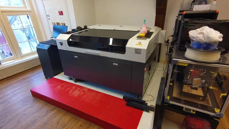
At the Waag, there is a large 130 Watt CO₂ BRM laser cutter with a 1300mm by 900mm bed.
3.1.1.1. Most important parts
Laser tube
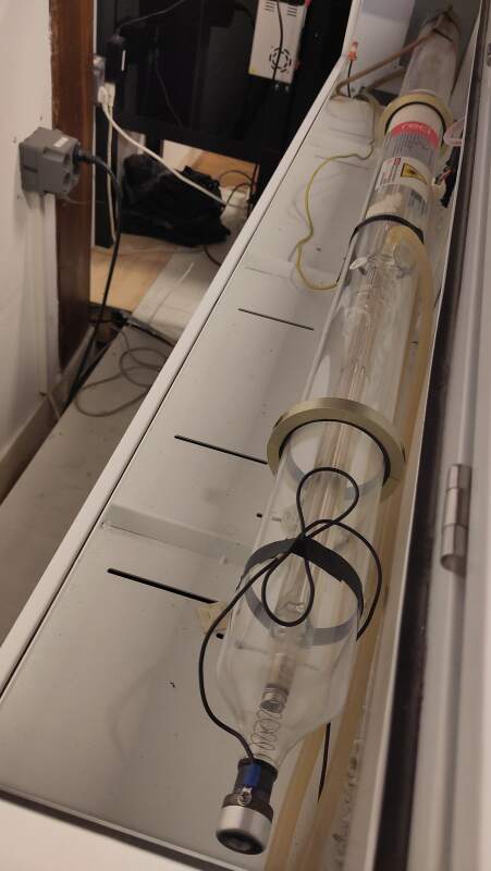
Figure 2: Laser tube (back of the machine) Head with lens (on a movable X-Y axis frame)
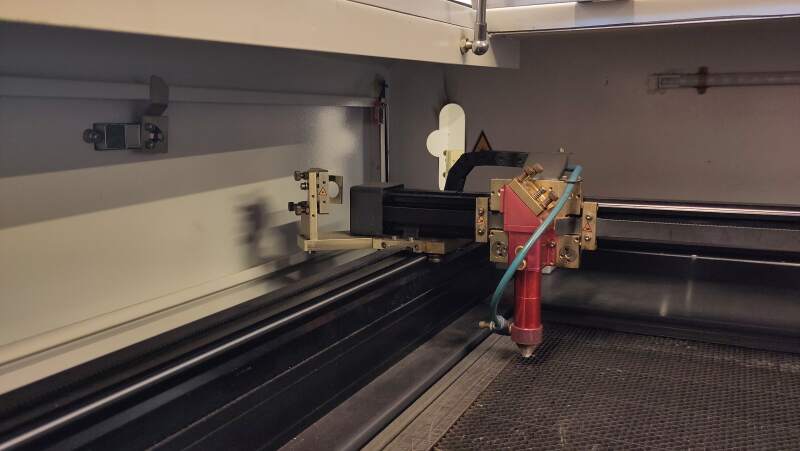
Figure 3: Laser light comes in via mirrors Water cooling system (cools the tube)
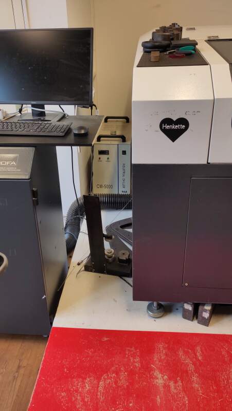
Figure 4: Water cooling system (behind the machine) Air compressor (blows along the focused laser)
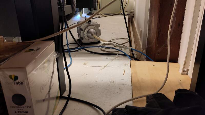
Figure 5: Compressor (behind the machine) Fume extractor with HEPA (particles) and Carbon (smell) filters
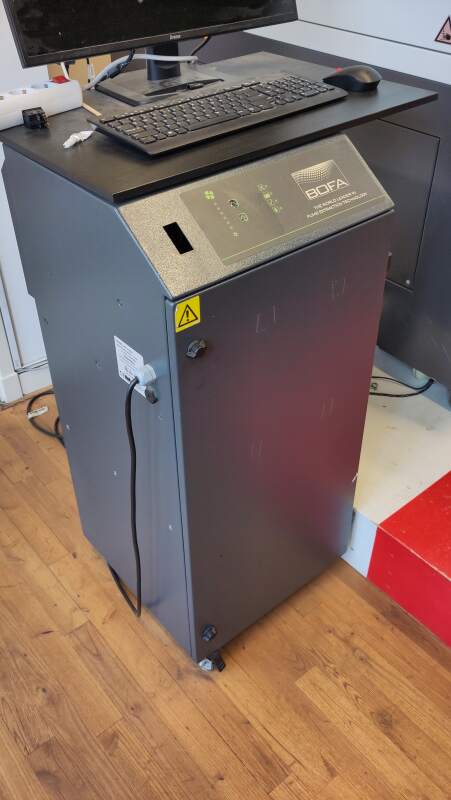
Figure 6: Fume extractor with keyboard and display for operating LightBurn - Controller (Ruida) to drive the motors and other parts
- Computer running LightBurn CAM connected over USB
The laser light is produced in the back by a large, water-cooled tube and directed into the top compartment of the machine by mirrors along the X-Y axes. A head with a fixed lens is positioned on the the X-Y axes.
3.1.1.2. Safe rules
- Check the spray bottle for water.
- Do not leave the machine (stay in the red area, see figure 1) while it is running (in case of fire that needs to be extinguished).
- Do not use the machine when alone in the lab.
- The machine will not operate if the hood is open.
- Use the spray bottle to put out fire.
3.1.1.3. Steps to run a cut
- Turn the machine on using the red knob on the right side.
- Within 2 seconds, press the reset button next to the red knob (the head should travel to the top right and tghen back to the bottom left).
- Turn on the computer located beneath the machine.
- Log in to the computer to the right of the machine.
- Start LightBurn (CAM software).
- Import the design SVG-file into LightBurn (its initial position on the screen is not critical).
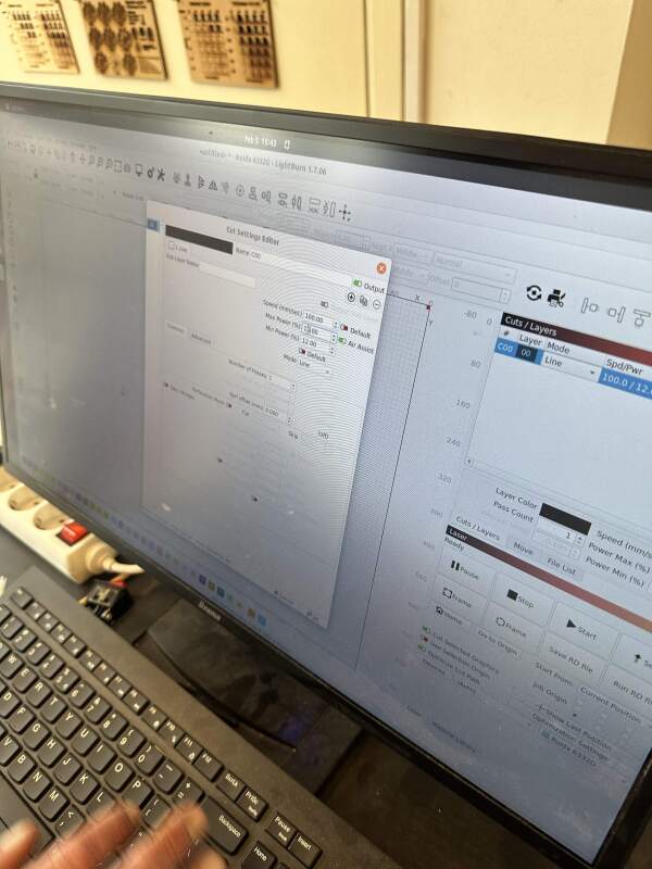
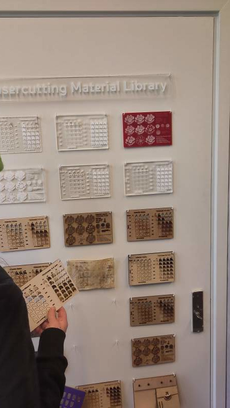
- Select Cut Settings (speed and power) in LightBurn's right-side "Layers and Cuts" menu (see figure 7). Use the samples next to the machine as starting points (see figure 8).
- Place the material on the bed under the hood with the head positioned at the bottom left.
- Focus the lens by placing the "puck" (piece off acrylic labeled "laser gauge) between the head and the material, unscrewing the tighteners to let the head rest on the puck, and then tightening it (see figure 9).
- Move the head with the cursor keys on the right top of the machine.
- Ensure the Job Origin is set to the bottom left in the bottom right menu (see figures 7 and 10).
- Turn on the fume extractor using the switch on the power strip on the computer desk.
- Turn on the laser using the bottom switch on the right side of the machine.
- Run a "Frame" in LightBurn to see if the laser will over the material.
- Press Start in LightBurn and enjoy the light show.
Notes:
- It's possible to select parts of the drawing in LightBurn and apply different power / speed settings to those sections by selecting a color at the bottom of the screen.
- Keep your eyes on the computer when using the Move buttons, as it's easy to inadvertently press the lower/raise bed buttons.
3.1.2. Tests (Group Assignment)
We conducted some tests for the group assignments.
3.1.2.1. Speed and power
We ran a series of tests based on the values from the Waag Laser Cutting Library (see figure 8) to determine the optimal settings for cutting our press-fit kits.
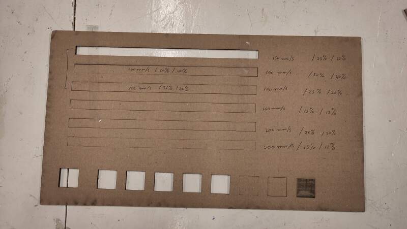
The top three cuts in figure 11 went all the way through. The boxes at the bottom represent our initial, somewhat random, cuts. The last one was a fill but we weren't particularly interested in that for our press-fit experiments.
3.1.2.2. Kerf
Christian described our kerf experiments on this page.
3.1.2.3. Focus
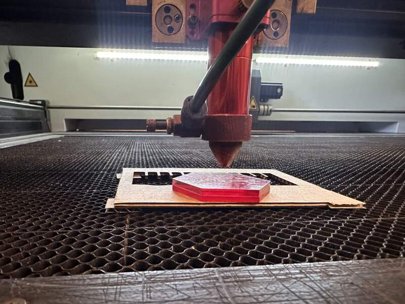
To perform a focus test, we placed the material on a slope (see figure 9) and focused on the middle. Unfortunately, the effect was invisible. When we made the slope more extreme and found that the area where the material was too close to the lens had a wider burn pattern (see figure 12).
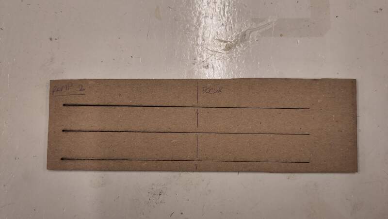
Interestingly the optimum seemed to be at 3/4 of the way down the slope. So, we asked Henk if perhaps the puck was too thick. Henk ran a test using a piece of scrap acrylic and confirmed the puck was fine as it is (see figure 13)
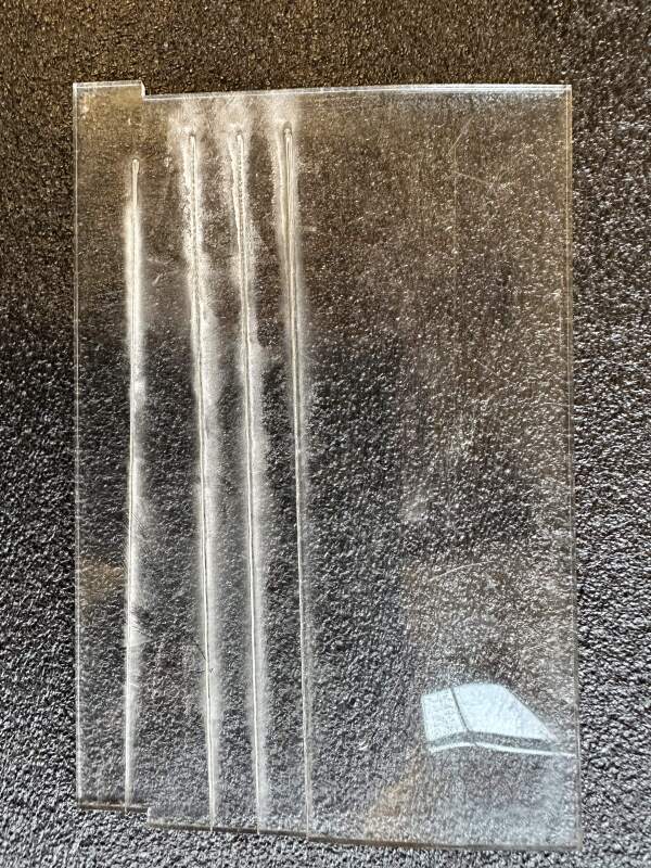
Cardboard and acrylic respond differently to focus, likely due to the inherent properties of the materials: cardboard is hollow, while acrylic is solid for instance
3.1.2.4. Joint clearance
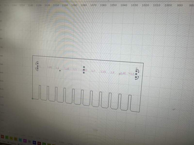
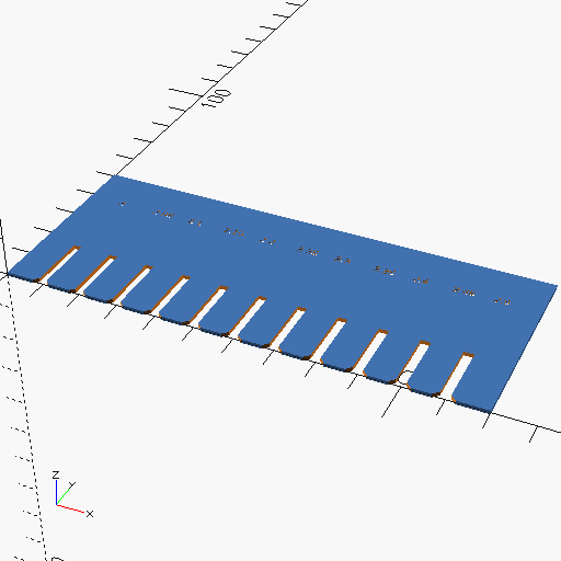
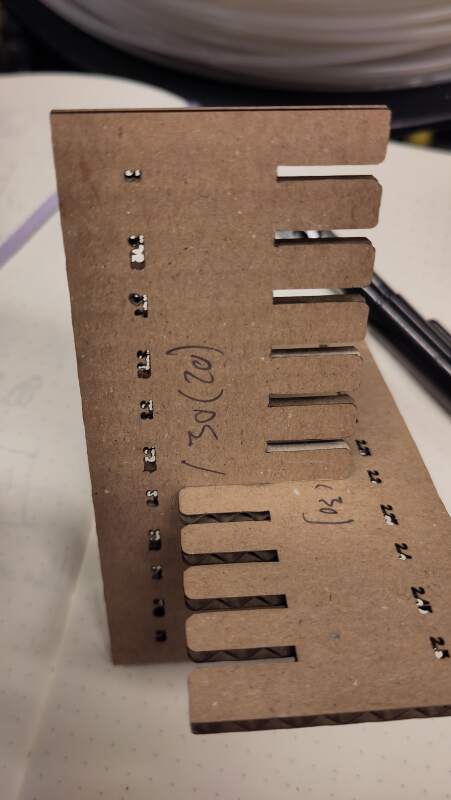
I wrote a s mall OpenSCAD script (inspired by our instructor Bas Pijls) to create an SVG file for a comb to test slots. It includes chamfers to make insertion easier and labels for the values. The following code creates slots from 2.0mm to 2.5mm for the 2.5mm cardboard we are using.
depth = 50;

thickness_start = 2.0;
thickness_step = .05;

slot_step = 10;
slots = 10;

difference() {
  square([slot_step * (slots + 2), depth]);

  translate([slot_step / 2 , 0, 0])
  for (i = [0:slots]) {
    thickness = thickness_start + thickness_step * i;
    translate([slot_step / 3 + slot_step * i, 0, 0]) {
      square([thickness, depth / 3]);
      translate([0, depth * .75, 0]) text(str(thickness), size = 2);

      ct = thickness * 1.5;
      x = sqrt(ct * ct + ct * ct);
      translate([thickness / 2, x / -2, 0]) rotate(45) square([ct, ct]);
    }
  }
}
I exported it to SVG and imported it into LightBurn. Initially, I tried without "stroke", but this resulted in an empty image in LightBurn.
While aligning the laser head, I accidentally pressed the "down" button and the bed changed position, causing Henk to jump up and intervene. The axis motors are strong and will rip the bed if the head is set too low!
I cut a couple of combs and settled on 30% maximum and 20% minimum laser power, with a speed of 100mm/s for a nice and clean cut out. Setting the power to 20% was insufficient to cut through on the longer runs (when the head reached full speed) and 30% burned the paper when the head moved slowly.
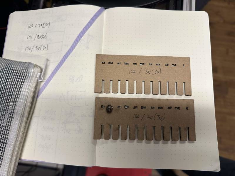
Having two combs with the slots cut correctly, I press-fitted matching sizes and felt 2.3mm was the sweet spot.
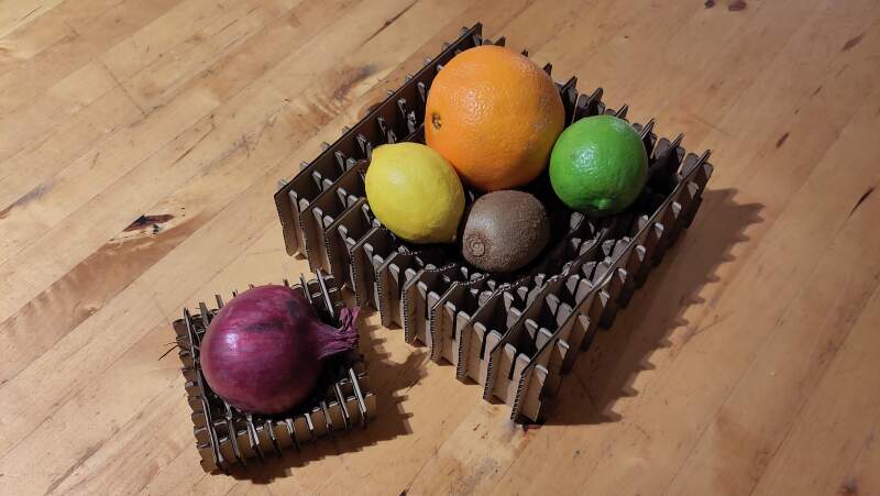
3.1.3. Fruit bowl
I wanted to create a simple fruit bowl: a basic cross raster with a sphere cut out.
bowl_w = 200;
bowl_h = 66;
bowl_t = 10;
material_thickness = 2.5;
steps = 20;

step_size = bowl_w / steps;

difference() {
  union() {
    for (i = [0:step_size:bowl_w]) {
      translate([i, 0, 0]) cube([material_thickness, bowl_w, bowl_h]);
      translate([0, i, 0]) cube([bowl_w, material_thickness, bowl_h]);
    }
  }

  translate([bowl_w / 2, bowl_w / 2, bowl_t + bowl_w / 2]) {
    sphere(d = bowl_w, $fn = 200);
  }
}
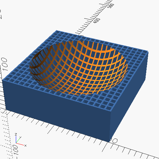
The laser cuts straight through so no angles are possible, making the model somewhat inaccurate. The next step is to create actual plates with a circle cut out straight.
bowl_w = 200;
bowl_h = 66;
bowl_t = 20;
material_thickness = 2.5;
kerf = 0.1;
steps = 20;

step_size = bowl_w / steps;
$fn = 200;

function radius_at(pos, radius)
= sqrt(pow(radius, 2) - pow(radius - pos, 2));

module plate (pos, top = true) {
  difference() {
    square([bowl_w, bowl_h]);

    sphere_y = bowl_w / 2 + bowl_t;
    sphere_r = radius_at(pos, bowl_w / 2);
    translate([bowl_w / 2, sphere_y, 0]) circle(d = sphere_r * 2);
  }
}

rotate([90, 0, 0]) for (i = [0:step_size:bowl_w]) {
  translate([0, 0, i]) {
    linear_extrude(material_thickness) plate(i);
  }
  #translate([0, 0, bowl_w]) rotate([0, 90, 0]) translate([0, 0, i]) {
    linear_extrude(material_thickness) plate(i);
  }
}
Calculating the radius of the circle to be subtracted required some extra effort but I got to use the Pythagorean theorem again.
This is better but now we need slots for press-fit joints. The following code adds slots at the top or bottom. The slots are chamfered to make inserting the plate for a joint easier.
bowl_w = 200;
bowl_h = 66;
bowl_t = 20;
material_thickness = 2.5;
kerf = 0.1;
steps = 20;

step_size = bowl_w / steps;
slot_width = material_thickness - kerf * 2;
$fn = 200;

function radius_at(pos, radius)
= sqrt(pow(radius, 2) - pow(radius - pos, 2));

module slot(y, top = true) {
  union() {
    square([slot_width, y]);

    ct = slot_width * 2;
    x = sqrt(pow(ct, 2) + pow(ct, 2));
    if (top) {
      translate([slot_width / 2, y - x / 2, 0]) union() {
        rotate(45) square([ct, ct]);
        translate([x / -2, x / 2, 0]) square([x, x * 2]);
      }
    } else {
      translate([slot_width / 2, x / -2, 0]) rotate(45) square([ct, ct]);
    }
  }
}

module plate (pos, top = true) {
  difference() {
    square([bowl_w, bowl_h]);

    sphere_y = bowl_w / 2 + bowl_t;
    sphere_r = radius_at(pos, bowl_w / 2);
    translate([bowl_w / 2, sphere_y, 0]) circle(d = sphere_r * 2);

    x_offset = bowl_w / 2 - sphere_r;
    for (x = [0:step_size:bowl_w]) {
      under_sphere = x > x_offset && x < x_offset + sphere_r * 2;
      y = min(sphere_y - (under_sphere ? radius_at(x - x_offset, sphere_r) : 0), bowl_h) / 2;
      if (top) {
        translate([x, y, 0]) slot(y, top);
      } else {
        translate([x, 0, 0]) slot(y, top);
      }
    }
  }
}

module preview() {
  rotate([90, 0, 0])
    for (pos = [step_size:step_size:bowl_w - step_size]) {
      translate([0, 0, pos]) {
      linear_extrude(material_thickness) plate(pos, false);
    }
    #translate([0, 0, bowl_w + slot_width]) rotate([0, 90, 0]) translate([0, 0, pos]) {
      linear_extrude(material_thickness) plate(pos, true);
    }
  }
}

preview();
translate([0, -bowl_w - bowl_h - 10, 0]) plate(bowl_w / 2, false);
translate([bowl_w + bowl_h + 10, -bowl_w - bowl_h - 10, 0]) rotate([0, 0, 90]) plate(bowl_w / 2, true);
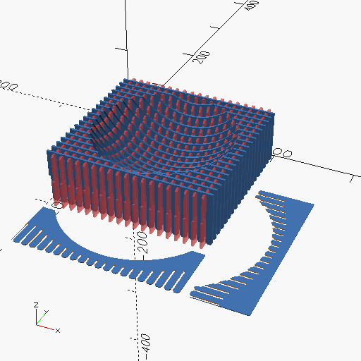
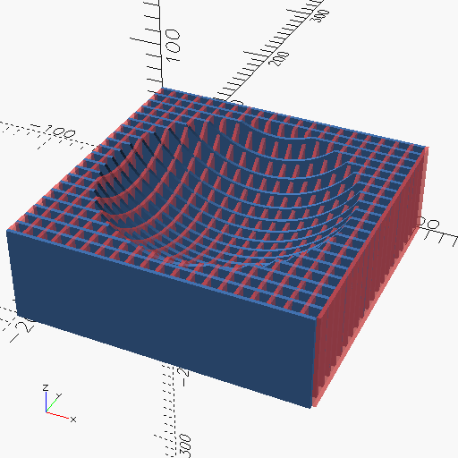
This is quite good! Figure 17 shows a preview of the result
is visible, along with two plates for the X and Y axes. Note that
kerf is not the actual kerf we measured in the group assignment but
a value used to get to the 2.3mm sweet spot found in the press fit test
(see figure 16).
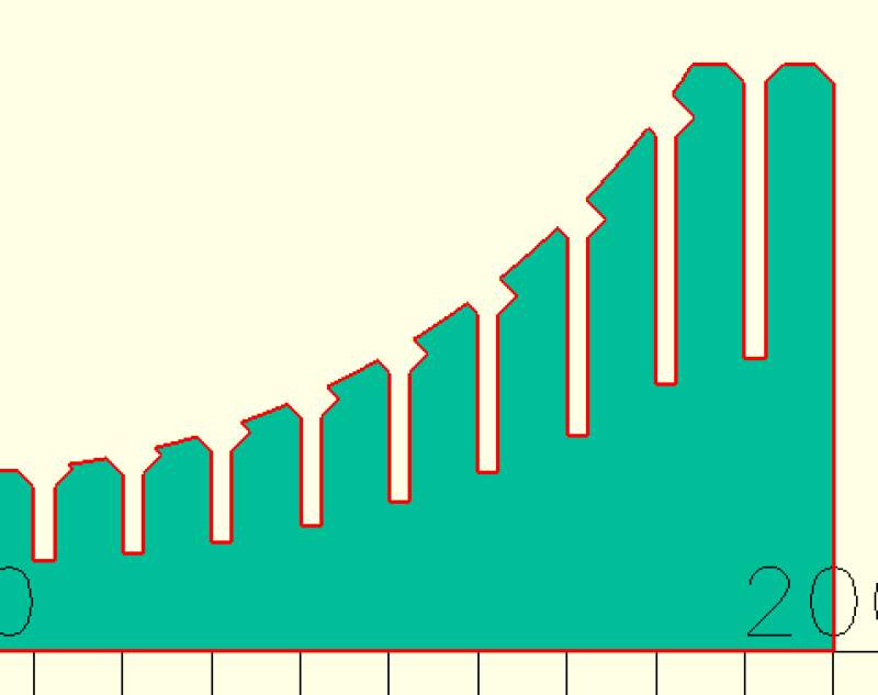
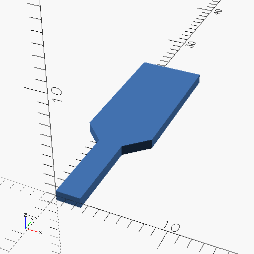
Creating the chamfer on the slots on the top side was a bit challenging due to the curve they are placed on. This curve sometimes resulted in a small, ugly hook on the slot (see figure 18). To mitigate this, I added an extra square cut-out (see figure 19).
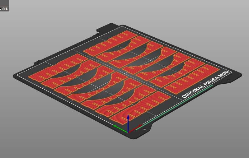
I created a layout for cutting using the following function:
columns = 4;
distance = 5;

module layout_translate(i) {
  x = (i % columns) * (bowl_w + distance);
  y = floor(i / columns) * (bowl_h + distance);

  translate([x, y, 0]) { children(); }
}

for (pos = [step_size:step_size:bowl_w - step_size]) {
  i = (floor(pos / step_size) - 1) * 2;

  layout_translate(i) plate(pos, false);
  layout_translate(i + 1) plate(pos, true);
}

I was very impatient and created a smaller version to create on a 3D printer for testing. I borrowed this idea from the week 3 documentation of Bas Pijls.
bowl_w |
80 |
bowl_h |
20 |
bowl_t |
5 |
step_size |
10 |
material_thickness |
1 |
kerf |
0.1 |
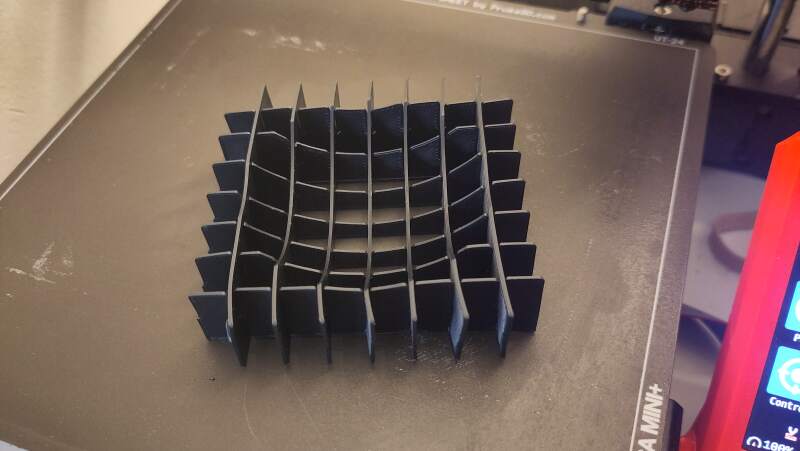
Meh, it's acceptable.
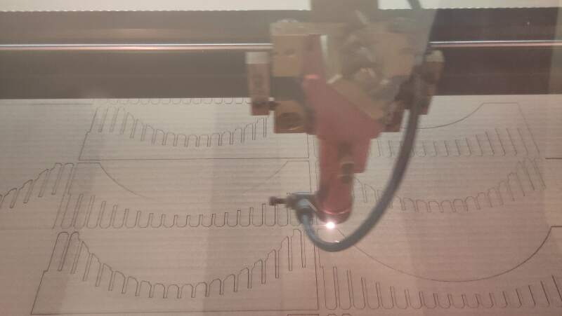
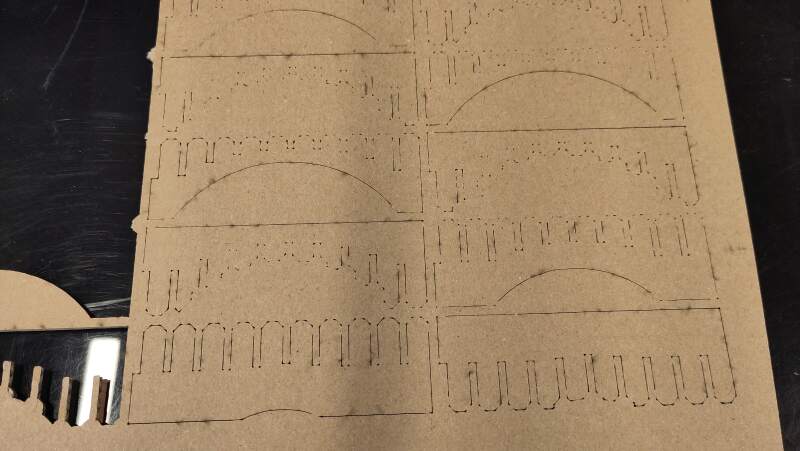
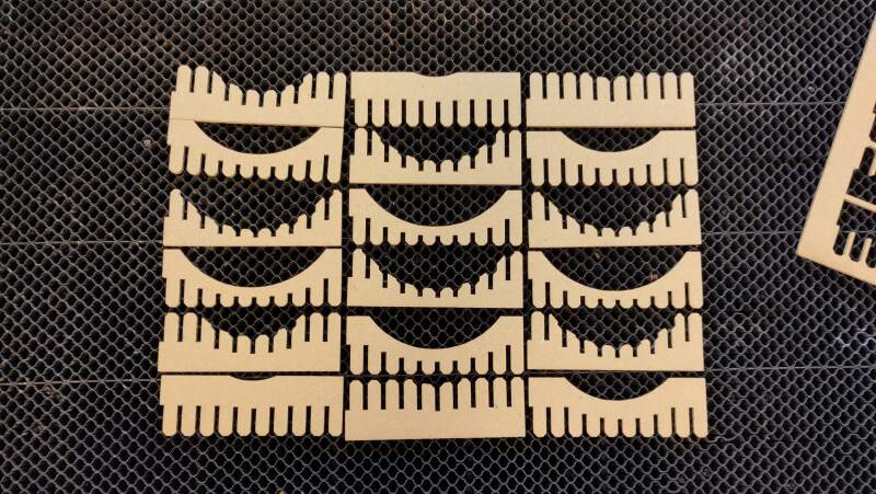
3.1.4. Cutting
After some trial and error on with the layout (to make it fit on a piece of cardboard), I copied my SVG file to LightBurn and ran the cutter at 100mm/s with power 30%/20%.
It took a while to finish, but the cutting was perfect. I forgot to add numbers to the design for assembly, so I used a pencil to number them.
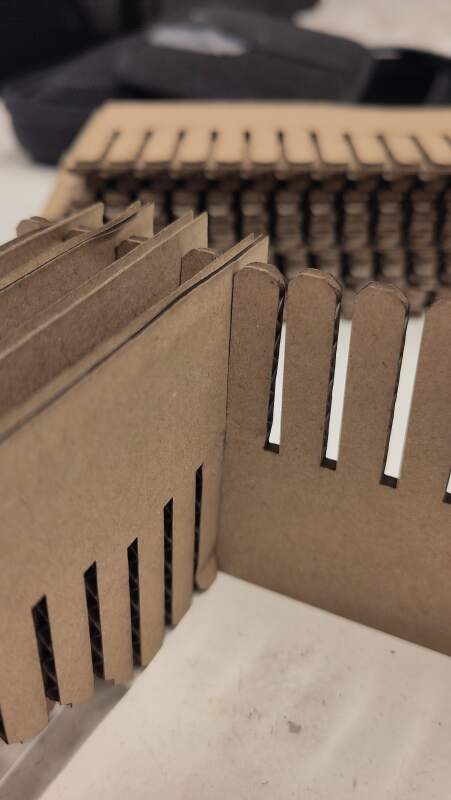
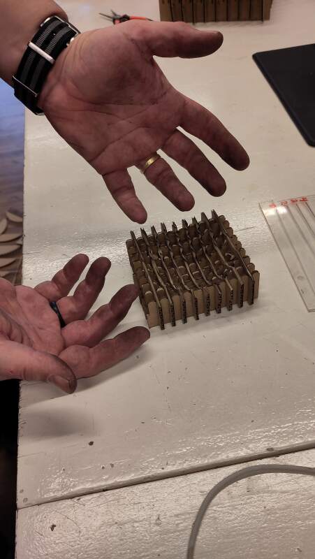
Putting it together was difficult because the slots were too tight. As clearly visible in figure 24, the "fingers" between the slots began to bend. I needed a flat nose pliers to assemble it and gave up after a couple of rows.
Henk advised me to make two by skipping slots. The first one turned out fine, but the second did not, as I used too many plates in the first. In the second bowl the plates became misaligned. It was too much work to fix it, so I left it as is.
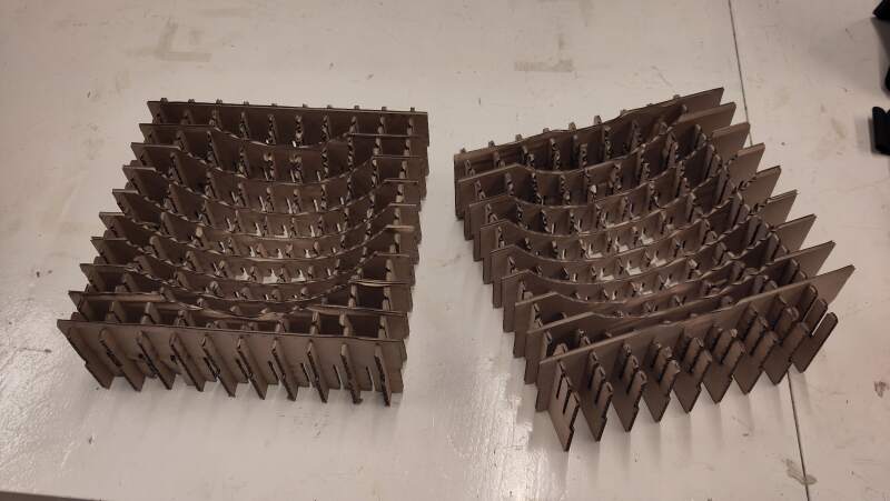
This was a failure, so I cut a second, smaller bowl with wider slots: 2.5mm instead of 2.3mm.
bowl_w |
100 |
bowl_h |
33 |
bowl_t |
10 |
material_thickness |
2.5 |
kerf |
0 |
steps |
10 |
I made the mistake of changing the laser power because I disliked the smoke stains on the back of the cardboard after cutting. I tried 25%/15% but this was unsuccessful. The cut did not go straight through, as visible on the back in figure 26.
I ran it again with the preview settings: 100mm/s and 30%/20%.
Again, I agot a perfect (though stained at the back) cut. Assembly was better but still very tight.
3.1.5. Conclusion
Cardboard is not a precise material. It is uneven and gets compressed when measured for thickness. The joint slots I created were all too narrow because the measurement I took was 2.5mm, but I should have measured a stack of pieces cut from the cardboard, then divided by the number of pieces to obtain a more reliable value.
The precision of a laser cut is very impressive. Removing cut cardboard from the machine feels like magic, as cutting it by hand would leave all kinds of dents and other imperfections. It's also loud and smells like fire.
3.2. Vinyl cutting
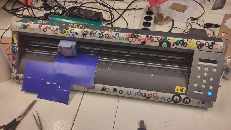
We will cut vinyl stickers using a Roland GX-24. This is a drag knife system (the knife can swivel around the Z-axis to go into the correct direction) connected to a computer through USB as a printer.
Before cutting:
- select force (set to 80g for our sticker test)
- move the sticker roll into the right position
- press origin
- press test
And tiny cut out is made which should not pierce the liner but will come off. See the many test cuts on the cutter on figure 29.
3.2.1. Design
I like the Atari ST busy bee and want to turn it into a sticker by replacing pixels with black and white dots.

Converting the pixels of such a small image into a text editor is
quite easy by converting it to XPM (using convert busy-bee.png
busy-bee.xpm) because the XPM-files are just C-code, and the image is
stored in a clear array of strings.
/* XPM */
static const char *busy_bee[] = {
/* columns rows colors chars-per-pixel */
"17 17 3 1 ",
"  c black",
". c white",
"X c None",
/* pixels */
"XXXXX.XXXXXXXXXXX",
"XXXX. .XXXX....XX",
"XXXX. .XXX.    .X",
"XXXXX...X.  ... .",
"X..XX.  .  .... .",
".  ...  . .... .X",
"X...  ..  ... . .",
"XXX.  .  . . . .X",
"XXXX..  .   ...XX",
"XXX.   . . .  .XX",
"XX.  ..        .X",
"X.  .... .  ....X",
"X. .... .  .    .",
"X. ... ..  .  ..X",
"X. .. . .. . .  .",
"XX.  . .XX.. . .X",
"XXX..X.XXXXX.X.XX"
};
In the above example, the Xs represent transparency, the spaces black, and dots white. I turned this into an OpenSCAD program:
data = ["XXXXX.XXXXXXXXXXX",
        "XXXX. .XXXX....XX",
        "XXXX. .XXX.    .X",
        "XXXXX...X.  ... .",
        "X..XX.  .  .... .",
        ".  ...  . .... .X",
        "X...  ..  ... . .",
        "XXX.  .  . . . .X",
        "XXXX..  .   ...XX",
        "XXX.   . . .  .XX",
        "XX.  ..        .X",
        "X.  .... .  ....X",
        "X. .... .  .    .",
        "X. ... ..  .  ..X",
        "X. .. . .. . .  .",
        "XX.  . .XX.. . .X",
        "XXX..X.XXXXX.X.XX"];

// select color here
c = ".";

// calculate step size
booklet_w = 130;
booklet_h = 195;
s = min(booklet_w / len(data[0]),
        booklet_h / len(data));

$fn = 200;
for (i = [0:len(data) - 1]) {
  for (j = [0:len(data[i]) - 1]) {
    if (ord(data[i][j]) == ord(c)) {
      translate([j * s, i * s, 0]) circle(s * .45);
    }
  }
}

// alignment markers
m = 5;
if (ord(c) == ord(".")) {
  translate([0, -m, 0]) square([m, m]);
} else if (ord(c) == ord(" ")) {
  translate([-m, 0, 0]) square([m, m]);
}
In this program, c can be set to select the color to render. I
placed a square in the bottom left corner for alignment when applying
the cuts as stickers. These should be removed after application.


3.2.2. Cutting
On the day of cutting, I decided against the previous design because I didn't have enough time to do two colors (and I'm unsure if both black and white vinyl were available). So, I opted for a chicken I discovered a couple of weeks ago while experimenting with fonts.

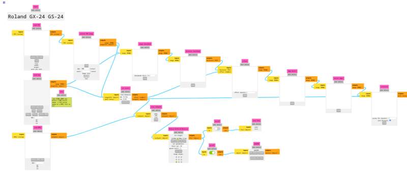
I created the above image using Gimp (Inkscape on my laptop seems broken as it does not produce text) and received instructions to transform it into an outline using modsproject.org. These are the steps to turn my image into something the Roland GCX-24 at the Waag can process:
- programs -> open program -> roland GX-24, cut
- select png file
- Roland GX/GS-24 Relative -> set force 80g
- on/off -> save file
- cut raster -> calculate
- save file
This yields a CAMM-file that I can cat to /dev/usb/lp1 on my
(GNU/Linux) computer.
I had all kinds of trouble trying to get the above to work on Google Chrome (using that because I was instructed to use WebUSB to send it to the cutter). The image would= not popup and send file would not do anything. So I opened mods in Firefox (Librewolf to be precise) and went for the save file path.
Next, on the cutter:
- Check if the knife is correctly sticking out of the head.
- Check if the head is tightly fastened.
- Position the sticker roll using the unlock switch on the back.
- Lock the sticker roll in place with the switch on the back.
- Make last position adjustments using the arrow buttons.
- Press Origin to make sure it starts at the current position.
Finally: cat chicken.png.camm > /dev/usb/lp1
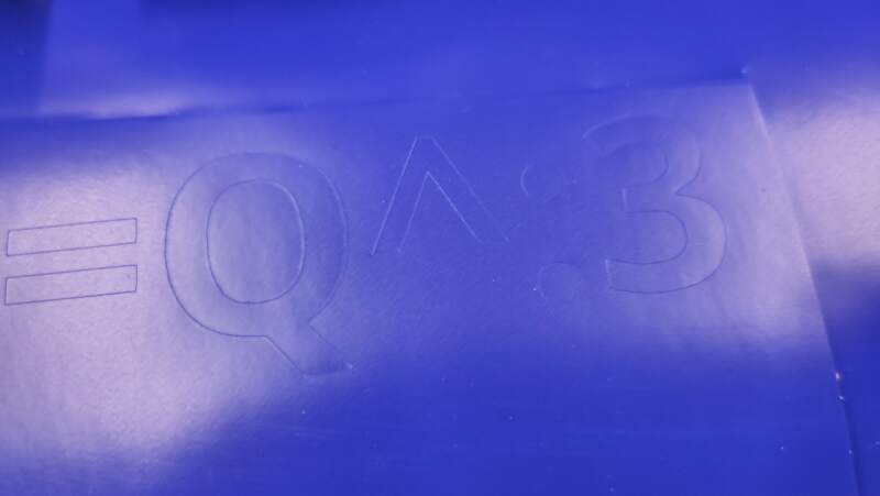
I cut out the part with the chicken on it, peeled off the extra material (weeding), put transfer tape on the rest and removed the release liner.
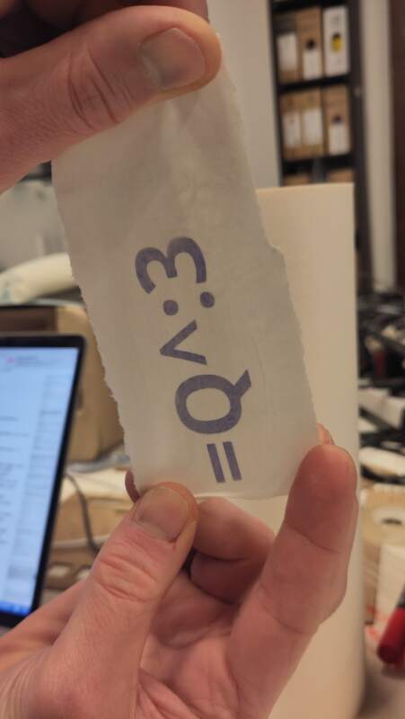
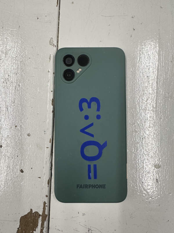
Then I stick it onto my phone are rubbed the parts with the sticker firmly. The last step: remove the transfer tape.
4. Reflection
This is the first week we've used machines, and it was a lot of fun! Christian and I cheered when our first tiny square was laser cut out of cardboard (and Henk rolled his eyes).
4.1. Good
4.2. Bad
I am not satisfied with the designs I created. They are very minimal. For instance, I could have used multiple joint types for the cardboard model. Using spartan tools like OpenSCAD consumes a lot of time, which I do not have.
Also, I'd like to do anther iteration on the fruit bowl. Make it bigger and not as boxy by lifting the edges from the table. Cut it out of wood (triplex) and find a way to get rid of the smokey by light sanding and oiling.
I need to make better photos, for instance, a measurement with the calipers in view.
4.3. Ugly
I had the opportunity to use the vinyl cutter rather late because the Roland was does not work (yet?), and the other machine (a Cricut Maker 3) can only be operated from a Mac or Windows computer after make some account, which I consider hostage-ware, so no thank you.
My inkscape seems to be unable to create basic text. Some how it is messed up. It may be packaged wrong (I am using Guix) but I have no time to investigate. Small things like this are starting to stress meo ut badly.
5. Source Files
Vinyl cutting:
- Busy Bee SCAD-file
- Busy Bee SVG-file (black)
- Busy Bee SVG-file (white)
- Chicken XCF-file
- Chicken CAMM-file
Laser cutting:
- Comb SCAD-file for testing joint sizes
- Bowl SCAD-file
- Bowl SVG-file
- Bowl SVG-file small version
- Bowl LightBurn file (original with slots too narrow)
