Computer-Aided Design
1. Week Assignments
This week assignment is:
Model (raster, vector, 2D, 3D, render, animate, simulate, …) a possible final project, compress your images and videos, and post a description with your design files on your class page
2. Prior Knowledge
3. Work!
3.1. OpenSCAD
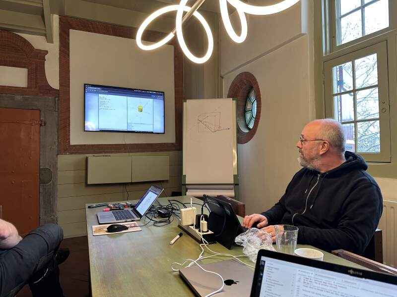
Because I have used OpenSCAD before, Henk asked me to give a short demo for my fellow students at the Waag, to show the basic features and shapes. I did not model my final project in OpenSCAD this week; instead, I reported on the demo I gave instead.
We worked toward the following script and I explained some features like:
- Making shapes like
cube,cylinderandsphere. - Using
$fn(number of facets) to make smoother spheres. - Using
hullto making a shape by enclosing two or more shapes. - Using
translatedto position a shape. - Using
differenceto do a boolean subtraction of a shape. - Using
moduleto combine operations. - Using
#to highlight a shape for debugging.
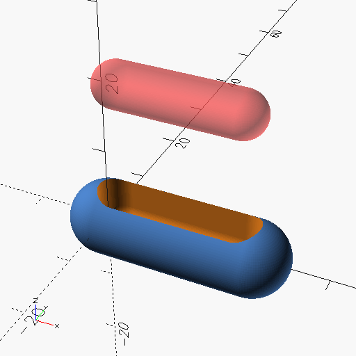
$fn = 100;

module ding (l, d) {
  hull() {
    sphere(d = d);
    translate([l, 0, 0]) sphere(d = d);
  }
}

difference() {
  ding(20, 10);

  translate([2, 0, 0]) hull() {
    ding(16, 6);
    #translate([0, 0, 20]) ding(16, 6);
  }
}
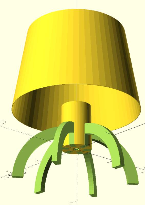
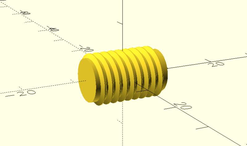
We also did a small demo of the enormous BOSL2 library to show that anything is possible in OpenSCAD.
include <BOSL2/std.scad>
include <BOSL2/threading.scad>

$fn = 200;
threaded_rod(d=10, l=15, pitch=1.5, orient=BACK);
To get the above to work, clone the git repo into the same directory as the above SCAD file.
After praising OpenSCAD (because it's just programming), we also talked about its disadvantages:
- It renders slowly when models get more complex.
- Putting everything in an x-y-z coordinate system is hard.
- Needing to translate and rotate a lot when orienting parts relative to each other.
3.2. Inkscape
For the week assignment I wanted to make the front view of my final project and try to reproduce the standard segmented display digits. I had used Inkscape before but always in a hurry to get something done. This time I wanted to pay more attention to what it has to offer.
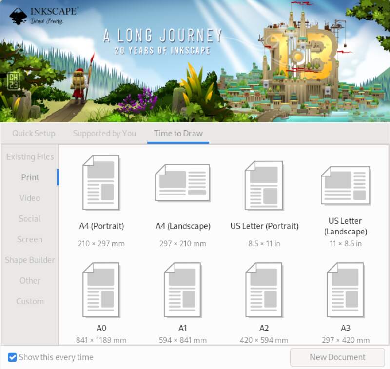
The opening screen is a bit confusing to me. It offers all kinds of formats and base shapes as starting points. Since I just wanted to make my own shape, I picked A4 landscape from the print section of options.
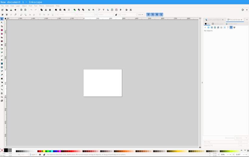
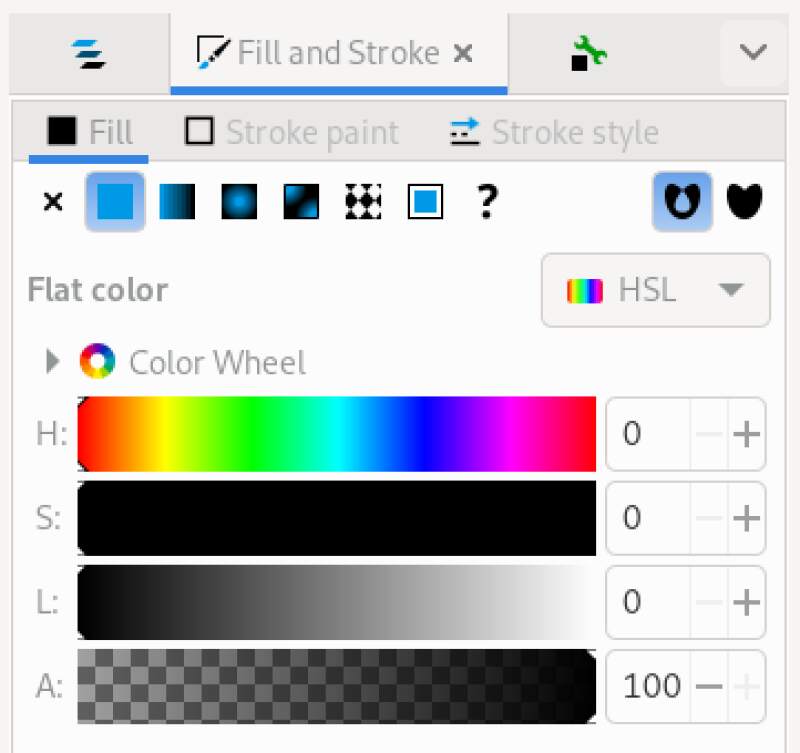
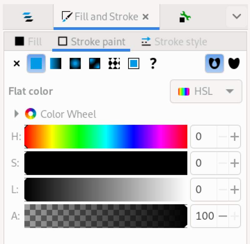
I wanted to drag a rectangle with finger friendly rounded corners as the outside edge of my alarm clock. The rectangle tool can be activated be activated and draws a big black box with sharp corners. The Fill and Stroke are adjustable in the right side panel but I only could change the color (which is a bit confusing because I needed to do some Hue, Saturation, and Lightness adjustments).
I wanted to change the stroke Join options but for so some reason it was grayed out.
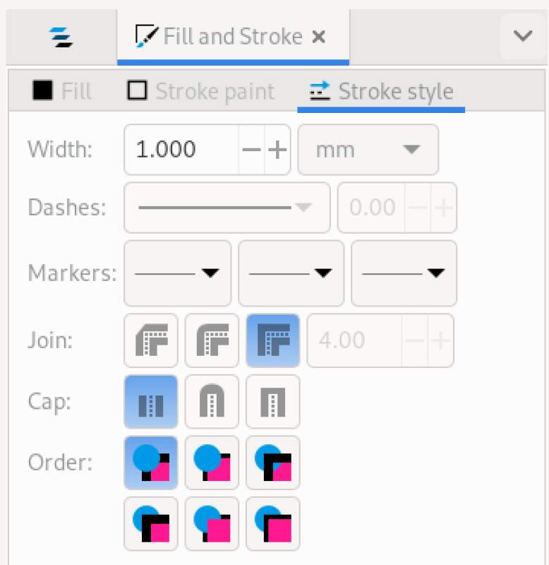
Ah! It does not work without selecting Stroke paint..
And now I could set the rounding..
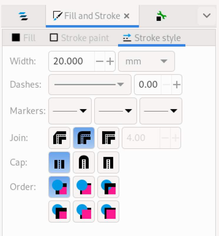
Experimenting I found the width determines the radius of the rounded corner. This is frustrating but I now had a box with rounded corners…

Note that the Fill and Stoke color were both black.
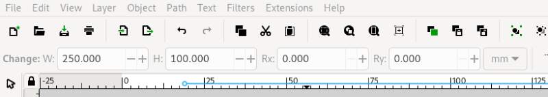
Now, let's set the width and height of this thing. It took me a while to find it but it's definitely not in the Object properties or some other tab on the right toolbar. It's on the top toolbar for some reason with the label "Change".
Using the Selector tool, I placed it in the top right corner of my canvas.
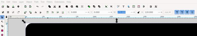
Now I could make another rounded box, make it white and put it on top of the black box. I wanted the black border to be 20mm so that's 250mm minus 40mm for the width and 120mm minus 40mm for the height.
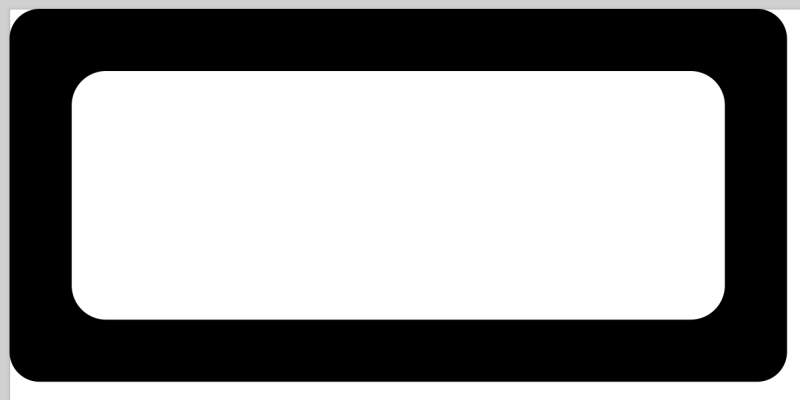
Ouch, this is ugly… The radius on the inner box was just wrong and I did not know how to make it perfect. What's worse: changing the width of the stroke also changes the width of the rectangle and the vice versa. Frustrating!!
After a break I realized I had not looked at any documentation. I must have thought my prior (superficial!) experience was enough to dive in. So I browsed through the tutorials and immediately found what I was looking for… This behaviour goes directly into my 4.3 list!
So, let's start over. Deleting shapes is easy (select with pointer
and hit delete key).
Drawing a rectangle actually provides a hint for creating rounding corners which I did not notice before.
Another thing I missed is the Rx and Ry on the size change widgets
in the toolbar (see figure 13).
Now, I could rebuild my rounded block, make a copy of it using the
Selector tool and doing select all (Ctrl-A), copy (Ctrl-C) and
pasting it (Ctrl-V). I scaled the copy down to 210x80, made it
white by adjusting the fill color and moved it to 20,20.

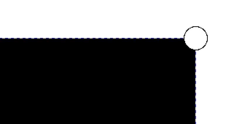
This looked better but I still did not like the inside corners. I
guessed because the scaling ratio for the x and the y differ the
Rx and Ry were scaled differently. I took the lowest value of the
two (Ry set to 13.333) and applied that to the other (Rx set to
16.800).

Slightly better. It still looked off to me but I left it for now.
Playing around with what I got now, I found out I did not have to manually set the position of the inner box but could use Align and distribute from the Object menu to center the object relative to each other by selecting them both.
Anyway, base is done. Let's group them into a single object so I
can't mess up when moving them. Use select tool Ctrl-A and
Group from the top toolbar.
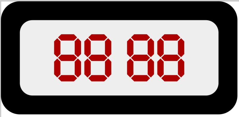
Now I wanted to try and make a seven-segment digit (like on your microwave oven). The Wikipedia page about seven-segment displays contains an SVG licensed under CC0, so I can do with it what I want. I imported it into my design to see if I could. Go to File and Import and select the file; now I get this dialog.
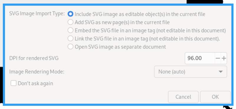
The default values looked fine to me, so I hit Ok.
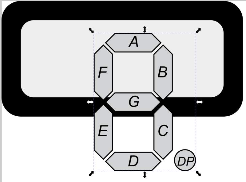
It's huge and note the "DP" dot – that is the 8th segment, so it has to go.
After importing, a new object is added to the tree view of Layers and Objects in the right-side toolbar.
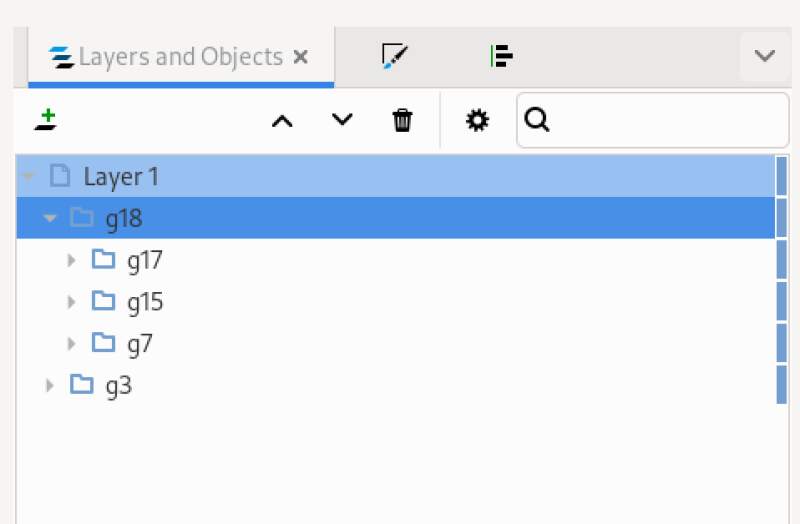
I opened it and found the element defining the dot by selecting nodes
and seeing it light up (with the dotted box and resizing handles). It
was g17. Right-click on that element, Cut, and it's gone. All the
letters on the segments were in g15, so they were easy to remove too.
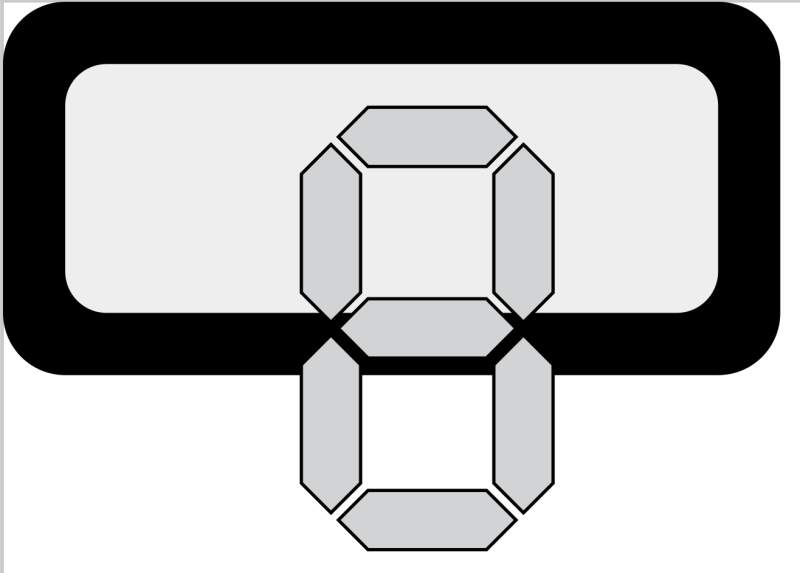
With the remaining g7 object selected I removed the stroke and
changed the fill color to an "alarming" red.

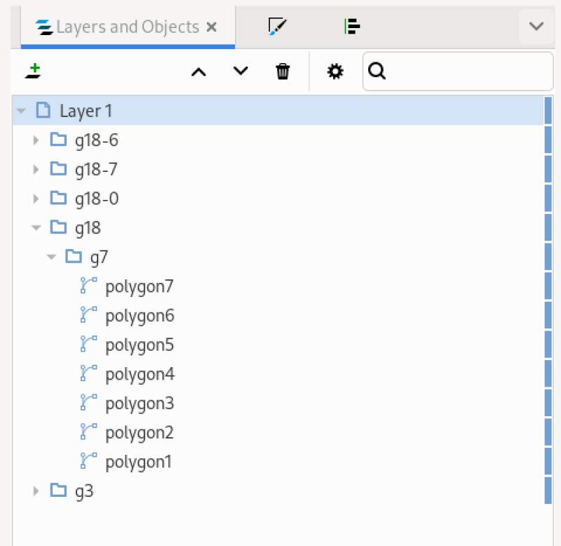
Next, I made copies and arranged them horizontally. I found it easier
to use the Layers and Object tree to select, then click shapes on
the canvas. So I right-clicked on g7, select Copy, selected
Layer 1 and pressed Ctrl-V three times to make four digits.
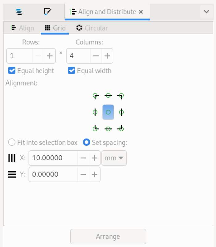
Now, I selected all four objects in the Layers and Object pane and used the Object Align and Distribute tool to place them into a grid.
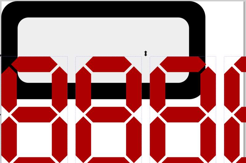
Next, I scaled them into the frame size I designed earlier because it was becoming unwieldy.
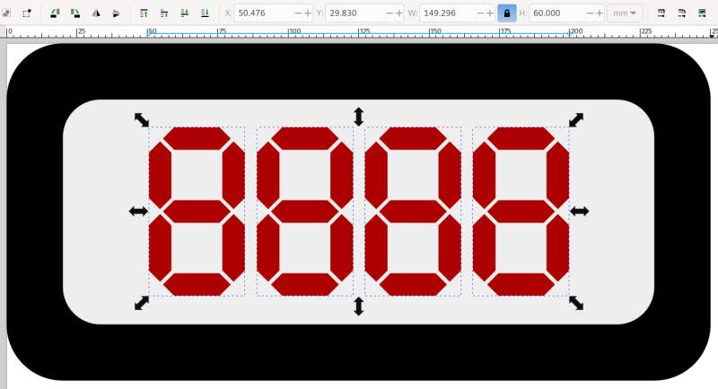
Note, I placed the digits free hand at first but will use Align and Distribute when I have the clock ready. Also note, I used the lock icon when scaling the digits other with the aspect ratio gets messed up.
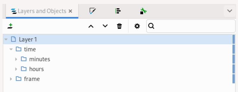
To improve readability, the hours and minutes should be grouped into two objects so I can move them apart move easily. I'll also rename the groups to make it easier to navigate them in the Layers and Objects tree view. I selected the digits in the tree view, hit the Group button on the top toolbar, selected the new group node in the tree and right-clicked to Object properties to change the name. Afterward I had "time" group containing "minutes" and "hours", and a "frame" group.
Now, I used the Align and Distribute tool again to put the "minutes" and "hours" groups into a grid and made some room between them. I selected the "frame" and "time" groups to use align (within the same tool) to center relative to the biggest object (the "frame").
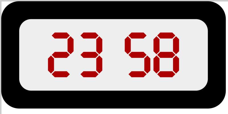
I disable some segments and tweaked the scale and placement for the final version.
3.2.1. Conclusion
I'm very happy my relationship with Inkscape improved after I found the documentation. It's a good tool for 2D vector drawing. I especially like the tree view of layers and objects to have a hierarchical view of what I am working on and being able to align shapes and groups relative to each other.
I did not explore parametric design in Inkscape; a quick internet search does not bode well. I'll need to put more time into that and ask around if it comes up.
3.3. FreeCAD
To get to know FreeCAD, I followed some episodes of the DigiKey Tutorials by ShawnHymel at DigiKey. The tutorial is pretty extensive and covers a lot of ground but luckily it starts with the basics. I followed along with the models he created in the first four episodes and tried (but kind of failed) to do the homework suggestion he made.
The FreeCAD workbenches I got to know are:
- Part Design
- Spreadsheet
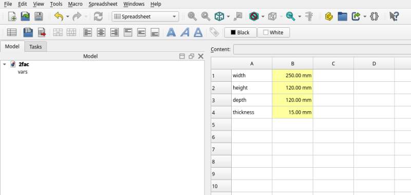
Let's start with a spreadsheet to get our sizes into one place. I'll
name it vars.
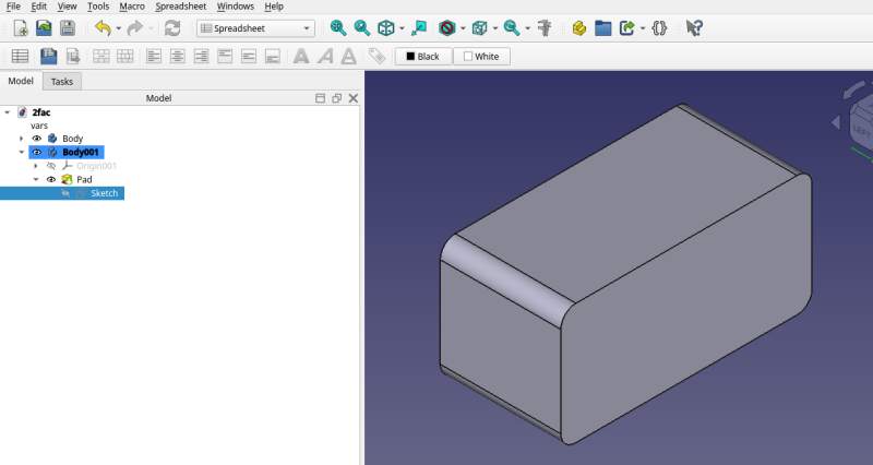
Switch to the Part Design workbench and create a "body" with a sketch on the XZ-plane. On this sketch a rectangle is drawn.
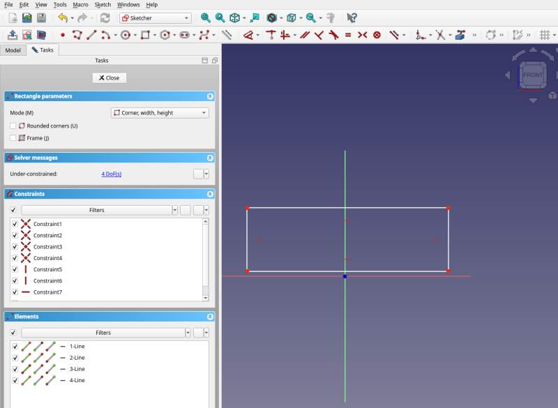
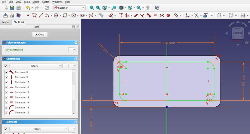
Using the Dimensions tool constraints were added for the width and height.
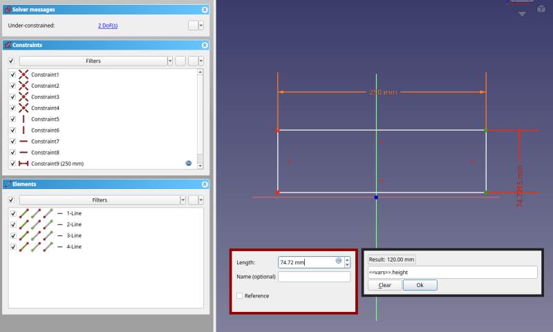
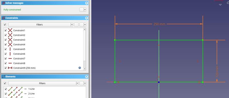
Make it fully constrained by using Constrain Symmetric on the bottom two points around the Origin point.
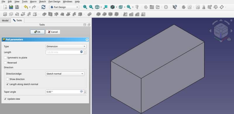
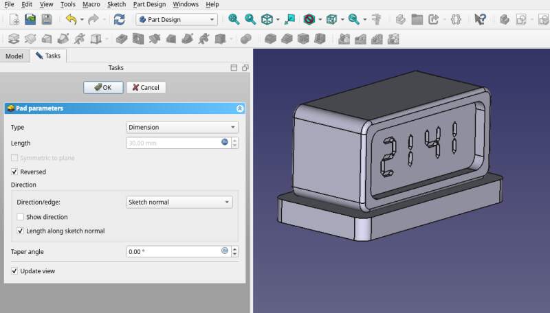
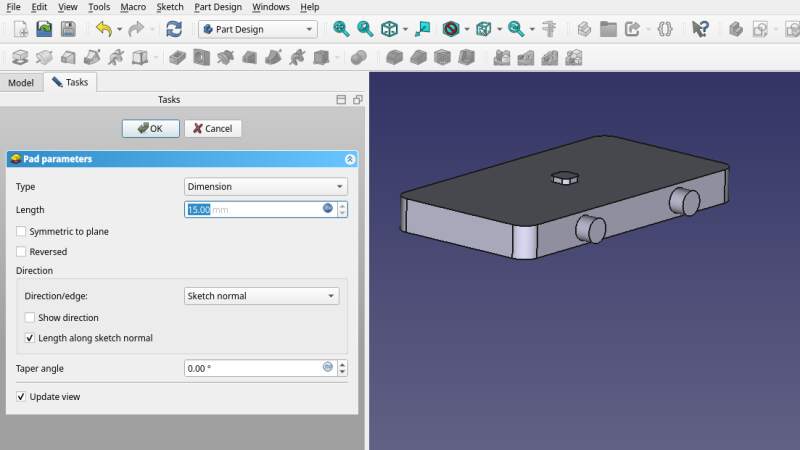
Use Pad to extrude a box from this sketch setting the length to
depth as defined in the vars spreadsheet.
Meh, let's get back to the sketch and use a Rounded rectangle
instead. I added a radius variable to the spreadsheet (value 15
mm for now).
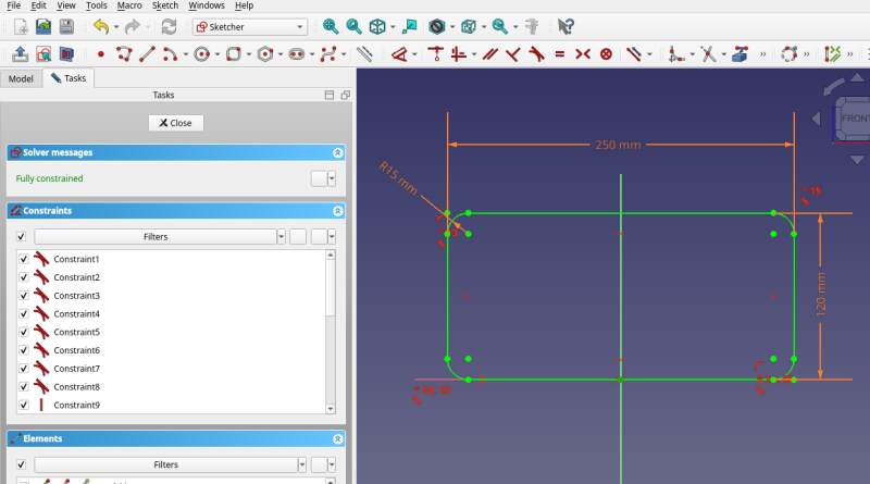
The padded shape updated automagically. That's nice!
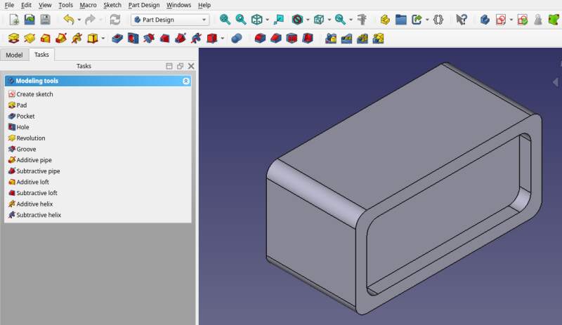
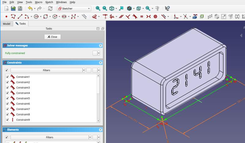
Sketch on the front to make a recessed panel for the time display.
Another rounded rectangle with width and height set to the spreadsheet
values minus two times the thickness (for example: <<vars>>.width -
2 * <<vars>>.thickness).
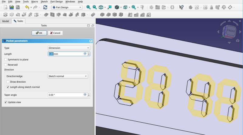
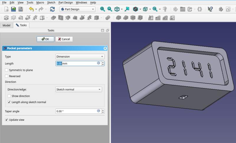
Now apply a Pocket to sink the panel into the box. The depth is
set to thickness from the spreadsheet.
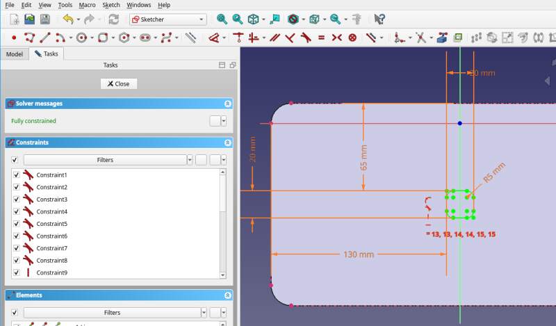
Is it possible to import the SVG from Inkscape at this point to make pockets for the digits? The menus do not allow me to import an SVG in sketch mode. Maybe I need a Binder (learned about this in the tutorial)? First I tried importing of a digits-only variant of the SVG I made.
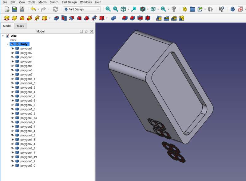
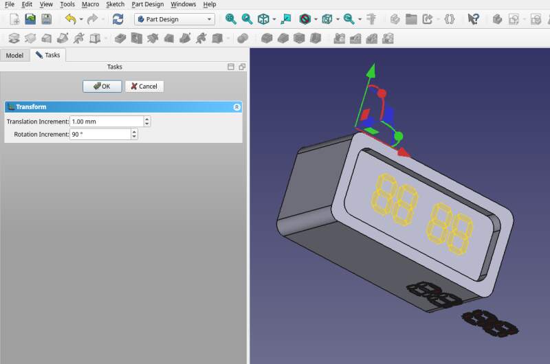
Ugh… I got a huge amount of polygons placed on the XY plane. I selected all of them and hit Create sub-object shape binder. Let's try and fix it. Placement only allowed me to push it around on the XY plane. Transform made me a bit more hopeful.
Okay.. let's try and make a sketch from this using Create external geometry. Well that kinda works.
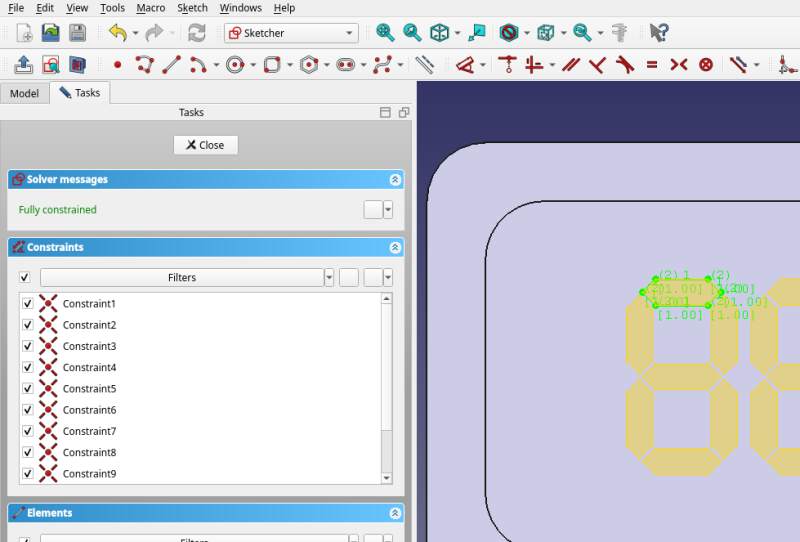
To do this I clicked the stroke of the digit segments with the Create external geometry tool and traced it with Create polyline. Ugh, tedious!
Let's see if we can make the placement of the binder stricter using
the vars. It has properties and some of them define the position.
The "freehand" values are pretty close to those in vars, so let's
replace them.
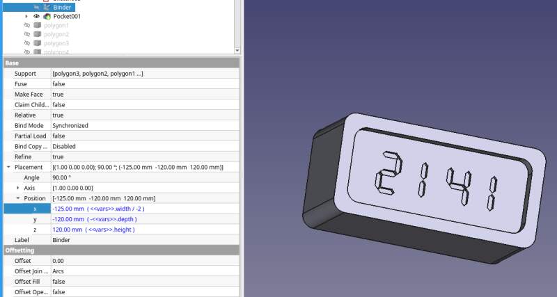
The alarm clock part is done! Next up: the dock. No, let's add some connector first with which it hooks up to the dock.
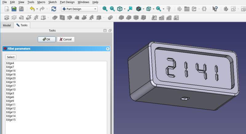
And, to be a bit more friendly for the touch, apply Fillet for all the sharp edges.
So, a new part and a new sketch to make a dock.
Use Pad (in the reverse direction because the clock starts at
z = 0).
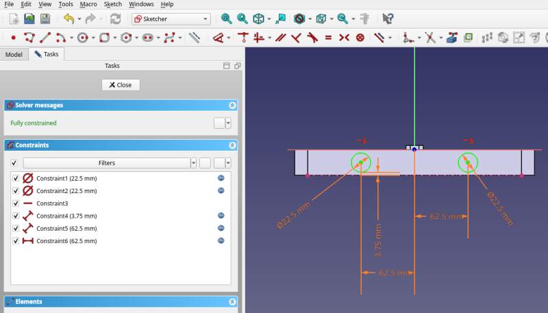
Sketch for the connector (note: I did not include a tiny gap to make it fit easily).
Pad and sketch knobs…
Pad…
And put them together!
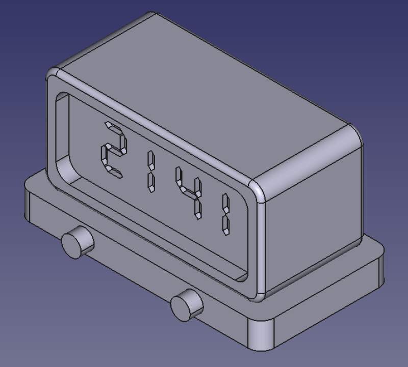
This is far from done. It is only an impression of what it could look like. The time/alarm selector button and power cable are still missing. The design itself isn't very 3D because the back side is just a plane, there's a lot more room for creativity here. Also, the imported SVG with a binder is not yet set up correctly because it does not scale when I change the values in the spreadsheet. And, how do I bundle up all those polygons from the imported SVG in the tree view? This is a mess…
3.3.1. Conclusion
It was a pretty steep learning curve and I barely scratched the surface! But using only the Spreadsheet and Part Design workbench gets me a long way. Selecting lines on a high-DPI screen is pretty frustrating too and I got it confused a couple of times with no other way out than to quit it and reload my model.
I am still more comfortable using OpenSCAD but I do see a lot of
advantages here. Stuff like fillets and holes with ISO-standard
measurements are very nice to have. The biggest improvement over
OpenSCAD is that FreeCAD allows me to start a sketch on a face of
my model which avoid a lot of rotate and translate headaches.
3.3.2. Cheat sheet
Here are some notes I made, playing around with shapes and following along with the earlier mentioned tutorial.
- Save often
- I had FreeCAD crash on me a couple of times or get completely confused when a bad constraint was added. The undo / redo features seem incomplete and can get you in a weird state, so if you mess up it is nice to be able to revert to a sane state.
- Navigation style "touchpad"
- Rotate with
Alt, move withShiftand zoom with two-finger scroll.
3.3.2.1. Sketcher
It's only possible to start a sketch on a planar plane. This can be the planes of the Origin (X, Y and Z), a flat face on an object, or a self-defined plane (I have yet to figure out how to define one).
- External geometry
- Makng construction geometry from outside the sketch with Create external geometry tool is very cool and automatically provides constraints.
- Binder
- Bring in a external part with the Sub-object Shape Binder. This can be an imported object but I only had success with STEP and SVG files. STL file do not work, it seems…
- Symmetrical constraint
- Select outer points first and then the center point.
- Distance constraints
- When applying to an arc (in a rounded box for instance), click the arc line and not the center point. The latter is likely to get FreeCAD into a weird state.
3.3.2.2. Part Design
- Additive / Subtractive shapes
- They are very easy to use and convenient but working from a sketch seems to work better for some reason.
- Pad
- Select a sketch and go, can do sub set of a sketch by selecting lines. But.. multiple shapes on a sketch will not operate on all of them?!
- Hole
- Make a sketch on a face of a circle of arbitrary diameter, the hole tool will configure the diameter.
3.3.2.3. Spreadsheet
Simply a free-form spreadsheet. To make cell values available in the expression editors, name the spreadsheet object in the tree view and set an alias on a cell through right click properties.
3.4. Blender
Let render some stuff!
So… I don't have any experience using Blender but I wanted to deliver on an animation this week. One of my sons does know how to operate Blender so he showed me. I took notes (yelling "slow down, what key did you press?!") and tried to reproduce it.
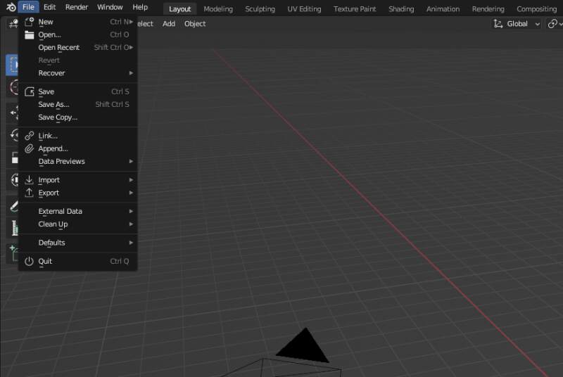
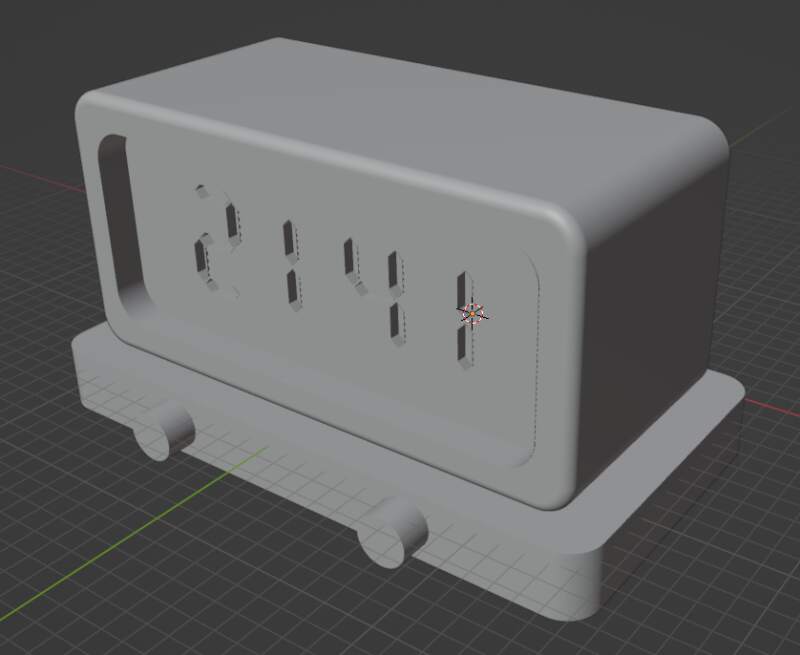
First we needed models to render so I opened FreeCAD again and made STL files from the clock and the dock. Select an object in the tree view and go to File and Export for both objects.
Launch Blender.
Select New File – General.
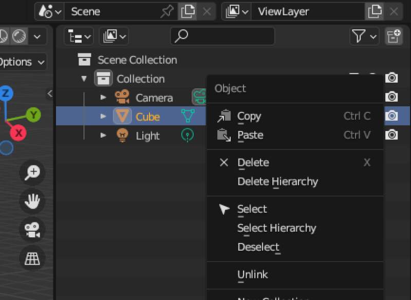
Remove the cube from the Scenery Collection on the right.
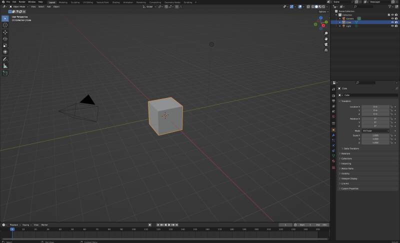
And import.
I can select both meshes in one go. There was some scale stuff I did not know what to do with.
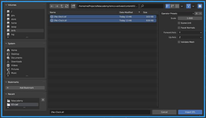
I guessed they are huge when I do not scale them?
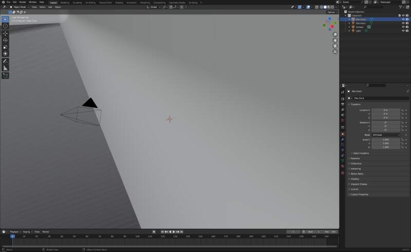
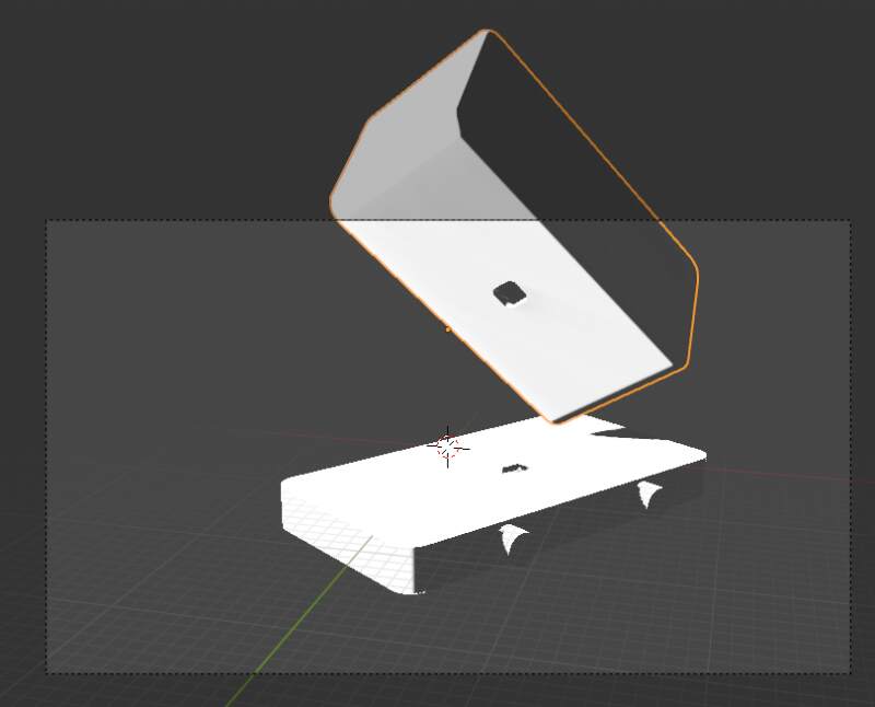
Zoom out using mouse scroll. It looked really sad…
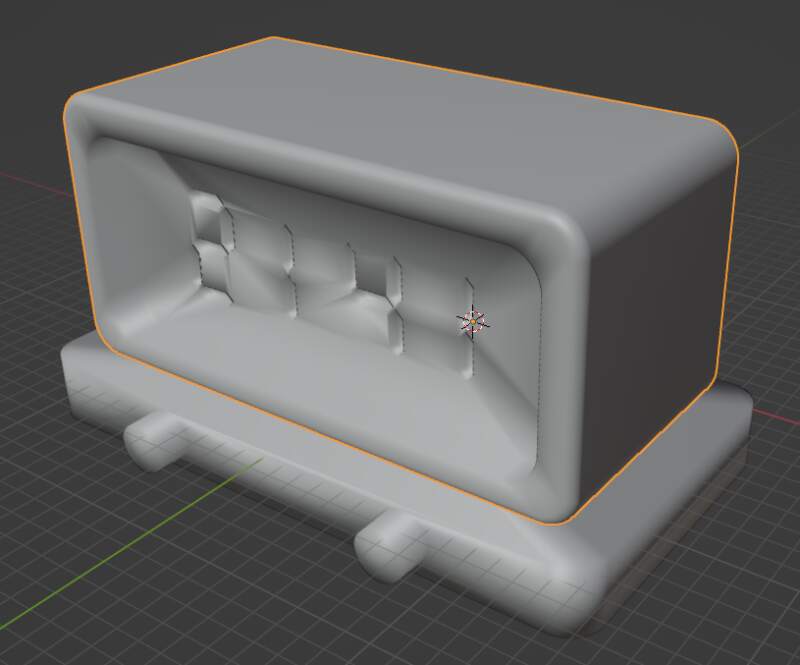
Right-click on the top model to un-blob it with Shade Flat.
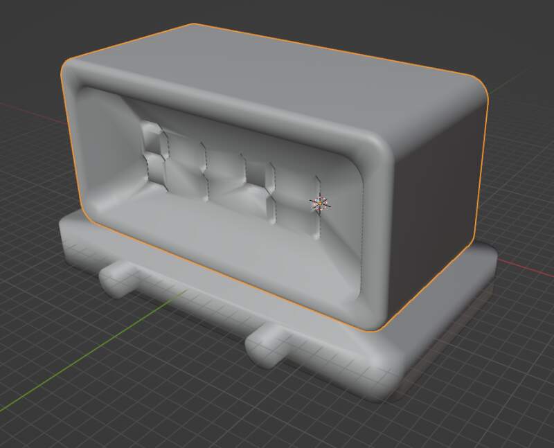
Now it looked good enough.
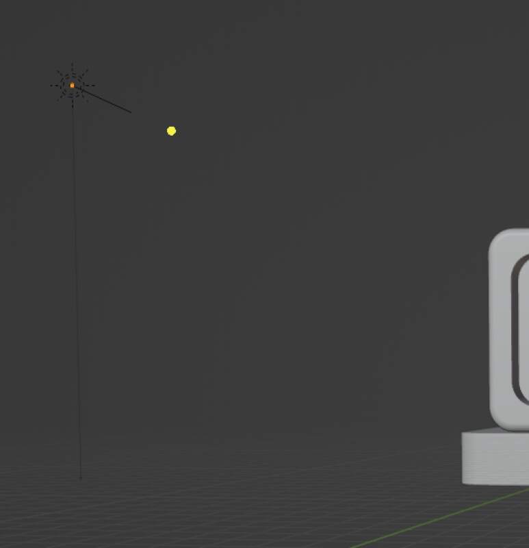
Move the light into position by selecting it in the Scene Collection
and hit g to grab it and y to move it over the Y-Axis (and similarly
for the X and Y as needed).
Change the light properties to "sun".
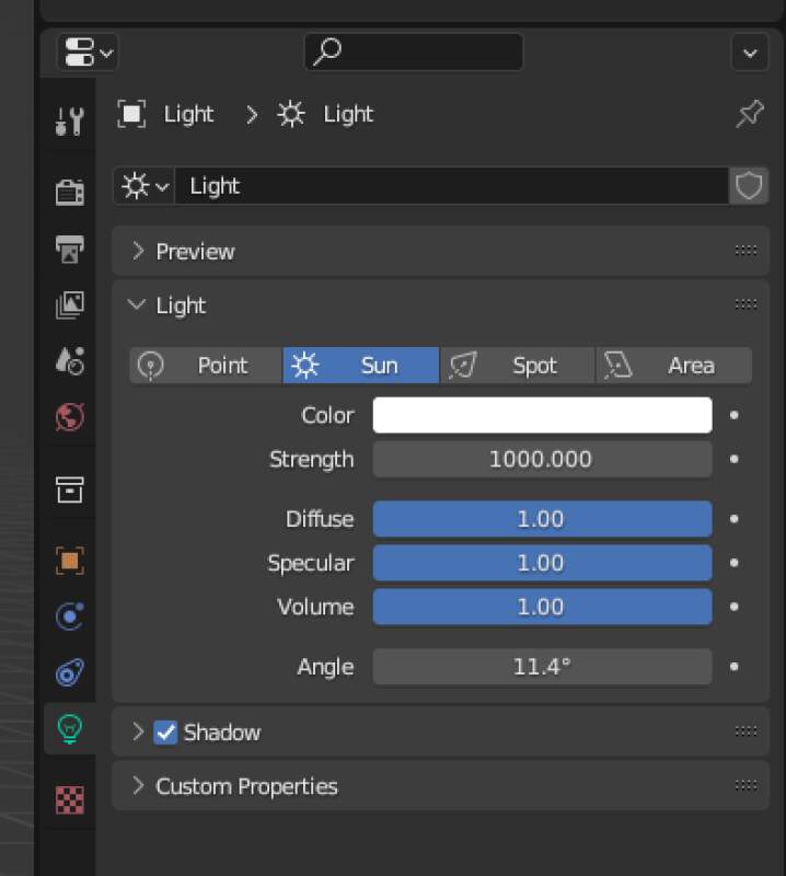
Now, because we made our light source a "sun", we can point it toward the object.
The top-right bubbles on the canvas can be used to set the Viewport Shading mode to "render". Now we can see the actual light bounce of the object. It's not pretty but it's just for previewing.
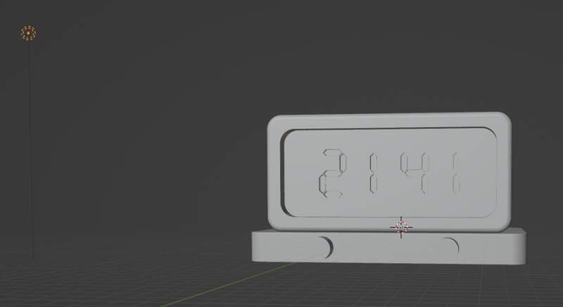
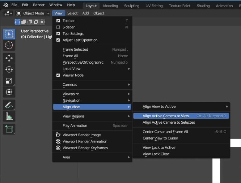
Setup the camera with View, Align View and Align Active Camera to View.
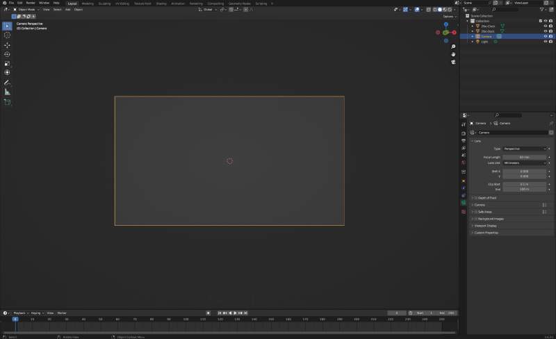
Bummer, I got a boxed gray camera view…
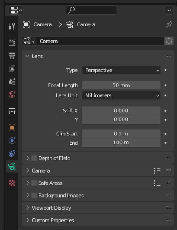
After some web searches, I found out it is a clipping problem. My
object was too far away. Fortunately we can fix that by setting Clip
End to something larger than 100m (this clock is big!!).
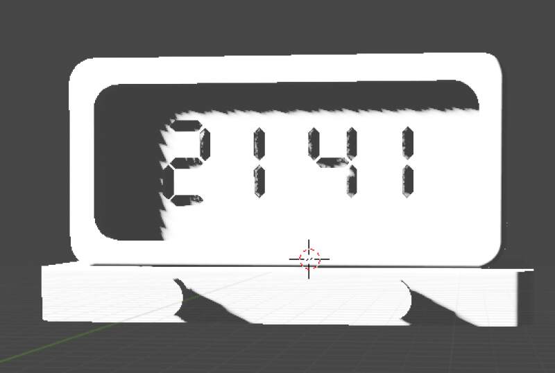
Yes, I got a picture!
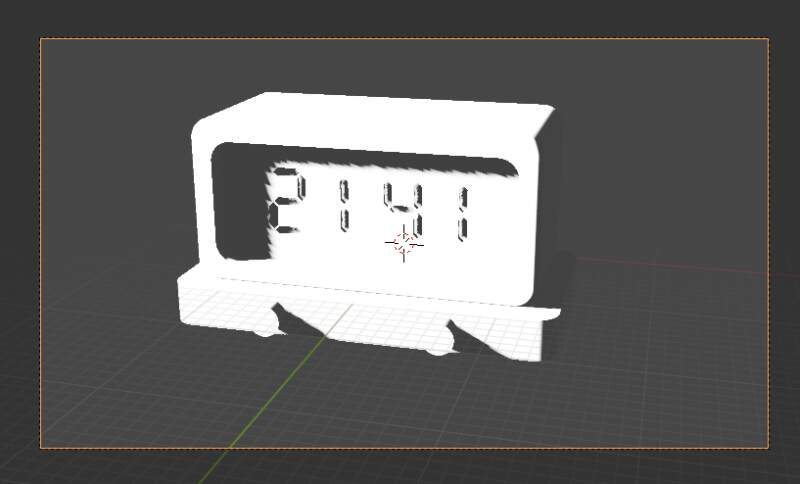
Finally we can start to make keyframes. There are several types but the only ones I understood were Rotate and Move. We'll rotate the object and lift the top part to reveal the connector at the bottom as our animation.
Select both model elements and hit i and r to drop a rotation
keyframe on frame 0.
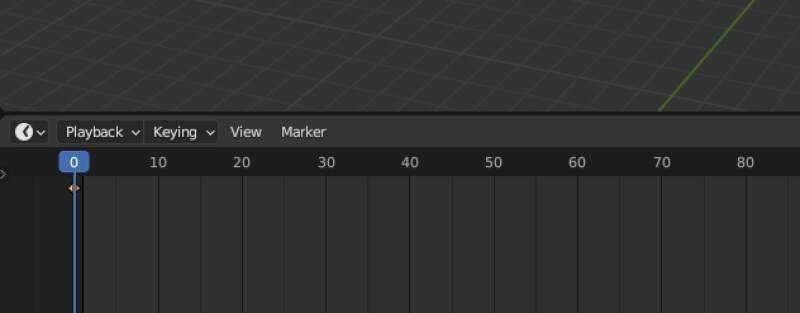
Select frame 100 on the keyframe bar and rotate the model by hitting
r, z (axis) and moving the mouse. Drop a keyframe with i and
r.
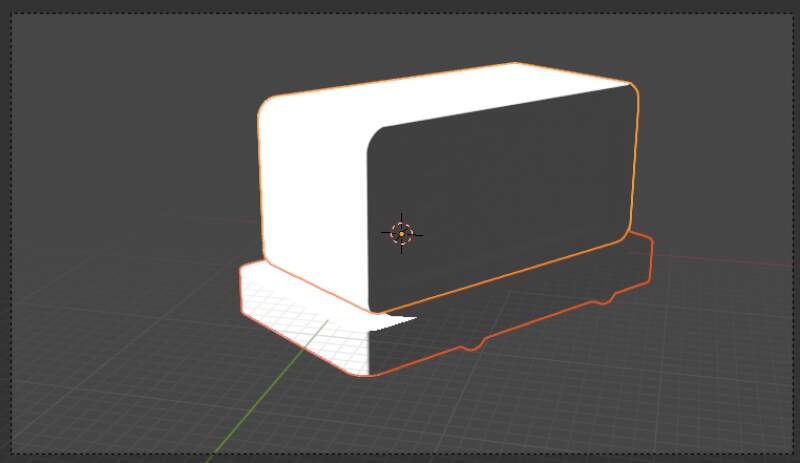
Now, only select the clock part of the model and drop a location
keyframe with i and l. Select keyframe 180 and move the clock up
with g, z and moving the mouse.
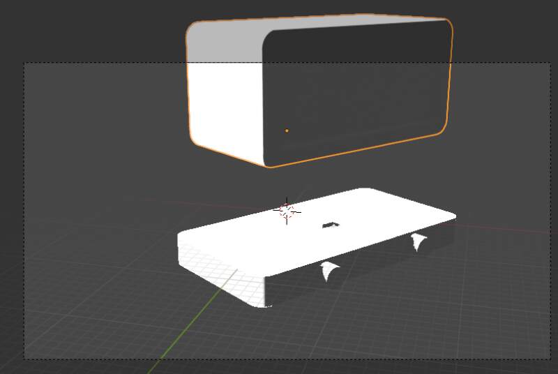
Select keyframe 120 and drop a rotation keyframe with i and r.
Go to keyframe 170 and rotate the clock with r, x and moving the
mouse.
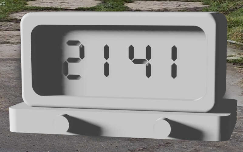
Animation done! The light was a bit harsh so I toned it down a bit. For rendering, first we needed to set the Output properties.
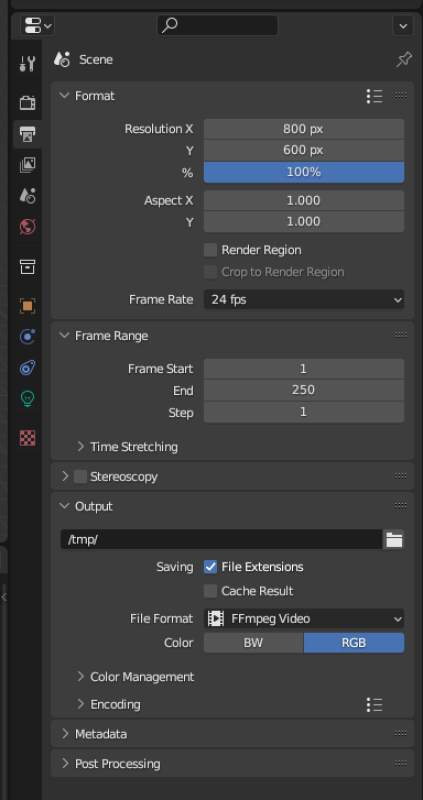
I changed the resolution to 800px by 600px and the file format to
FFmpeg Video. Then Render and Animation and waited for a minute
or two on my slow laptop…
Scoped the MKV video file out of my /tmp directory and converted it to a
smaller WEBM video file for on this page.
ffmpeg -i 2fac.mkv 2fac.webm
And here it is!
3.4.1. Conclusion
Blender is pretty cool but pretty hard to get started in. I was very lucky to have somebody to explain me the basics to me, but it was pretty tough to reproduce when he was not here. I do feel confident I can make more simple animation following the above recipe.
I probably will not use Blender for modeling this FabAcademy because would cost too much time to get into.
3.5. Gimp
And now for some raster graphics.
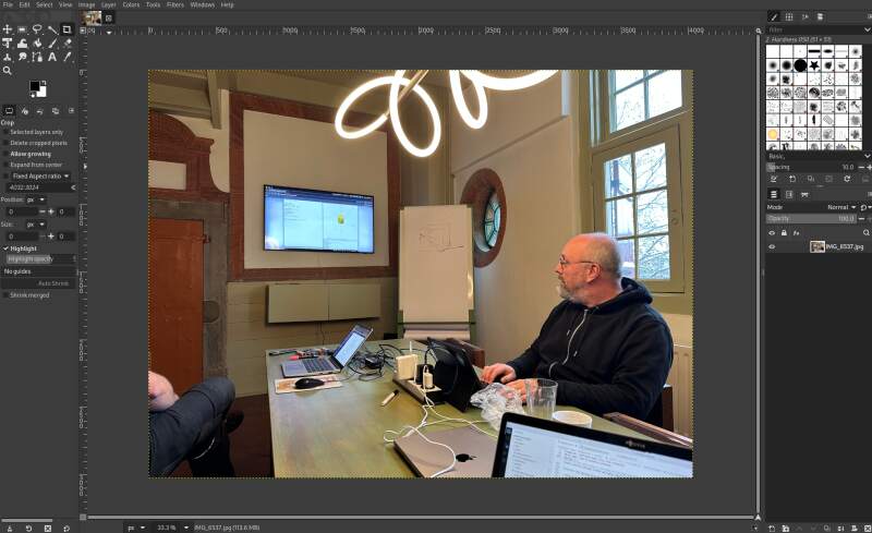
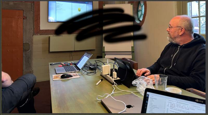
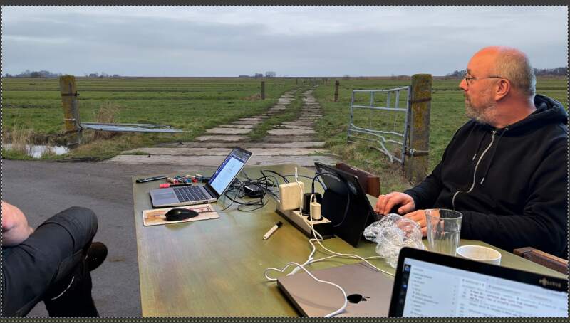
As mentioned, I've used the Gimp before to edit some photos so I know my way around its tools and layers. For this assignment I'll try to combine the photo of the 3.1 session with a photo I took while out for a walk some time ago. Hopefully I can make it look like I'm sitting outside instead of the Waag giving my demo.
Opening the original JPEG got from Christian, Gimp asks me about an embedded color profile in the image file.
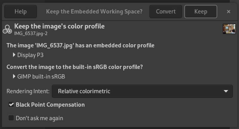
The Keep button is more prominent so I guessed that's the best option for now.
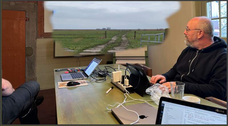
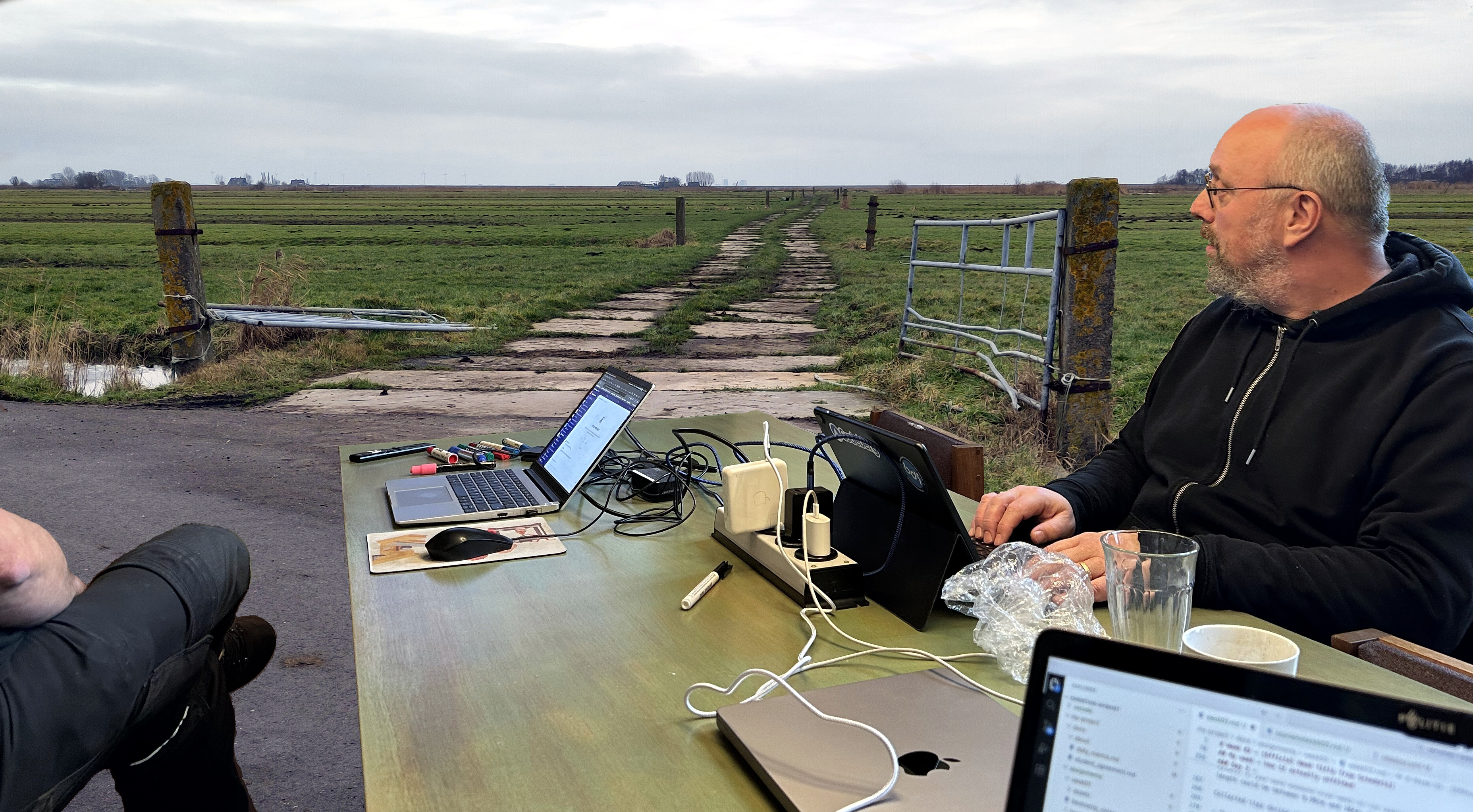
For the background I'll use the following image I took last week.
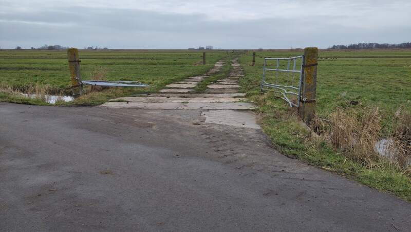
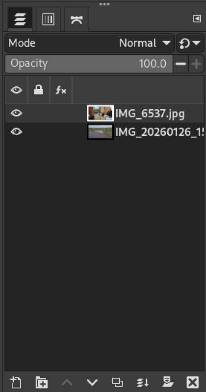
Open it using File and Open as Layers, it drops it on top of the demo image.
By adjusting the Opacity of the top landscape layer in the right layers pane, I made it see-through and moved the top layer (which will go to the bottom later) into a pleasing position using the Move tool.
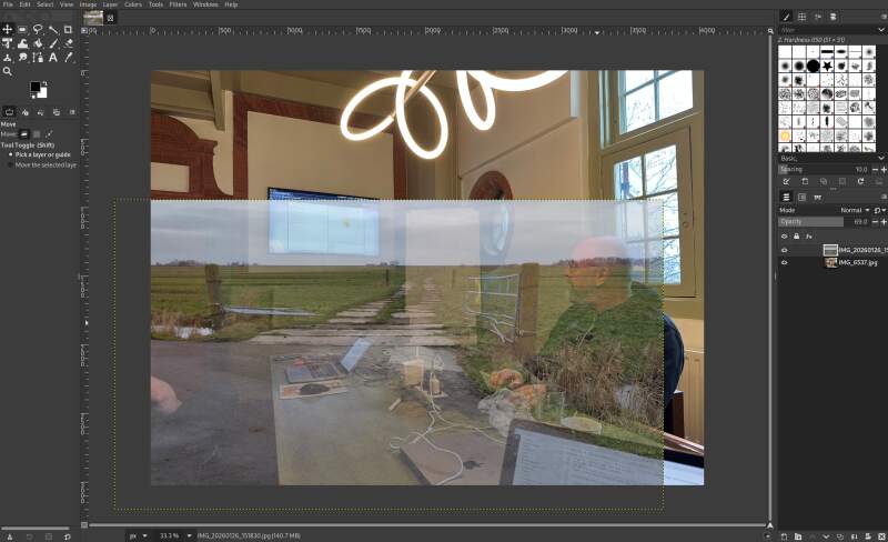
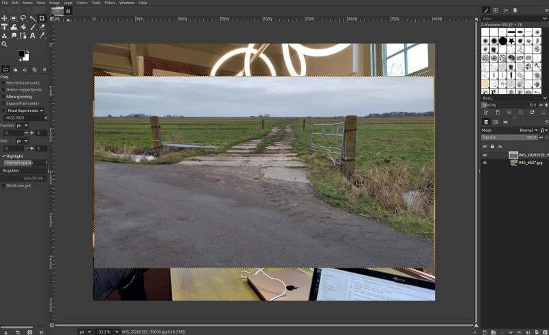
This looked nicely positioned with my head sticking out over the horizon. Next, take the intersection by using the Crop tool.
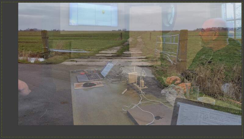
Note the dotted box around the image, that's the layer currently selected and cropping does not change the layer size. I have no idea why, but it did not bother me.
The stacking order was wrong so that needed to change using the Raise and Lower buttons at the bottom of the layers pane.
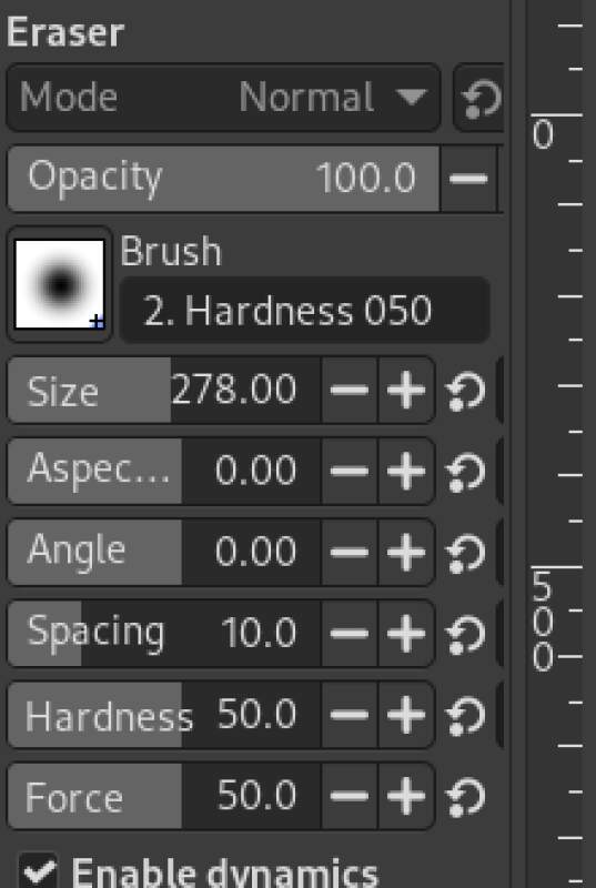
I also reset the opacity so now we could apply the Eraser tool and..
Ah, I forgot to the enable the alpha channel (the A in RGBA) on the top layer. Right click on the layer in the layers pane and select Add Alpha Channel. Let's try again.
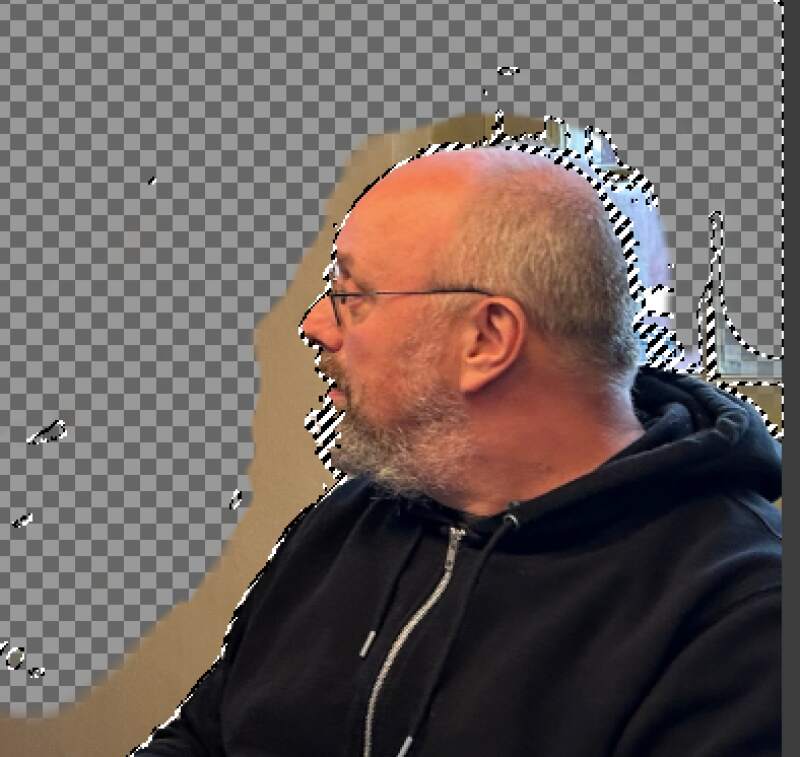
By making the background layer invisible (using the eye icon on the layer in the layers pane), it is easier to see what has been erased and what not.
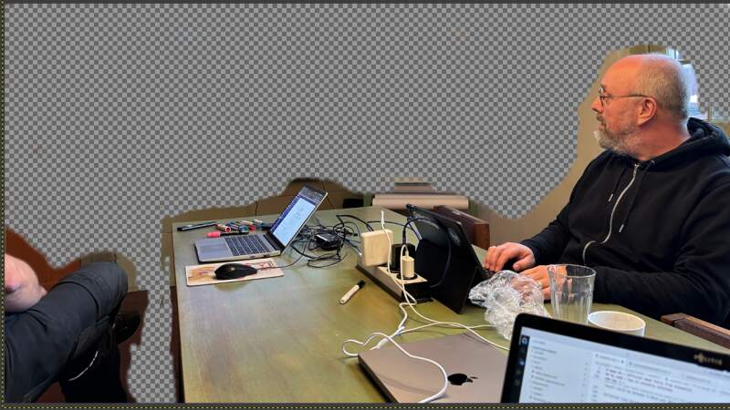
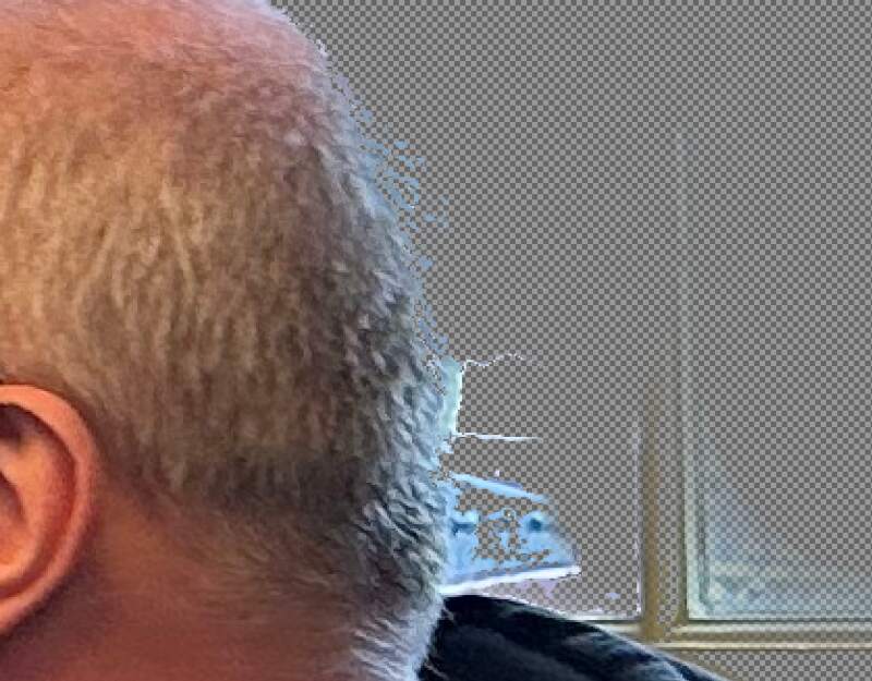
The edges are harder to erase. I zoomed in and gently continued with a smaller eraser using the tool properties.
But let's try the Fussy select tool (magic wand) to select an area
we can erase with broad strokes. Using the Shift key adds to the
selected area and Alt subtracts (when the tool was too greedy).
Note that broad strokes will probably shave off my beard so I needed to be careful here. After erasing with the selection active there was quite a bit of manual work left. Overall it was very helpful and a little bit of manual work remained after removing the selection with Select and None.
Using the magnifying glass Zoom tool to select an area to work on,
adjusting the eraser size and using the erase with the Alt to
"unerase" areas it worked out quite well. I applied the magic wand in
some smaller areas too and adjusted the Threshold down to make it
less greedy when needed.
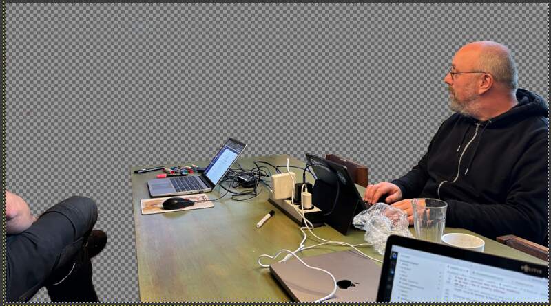
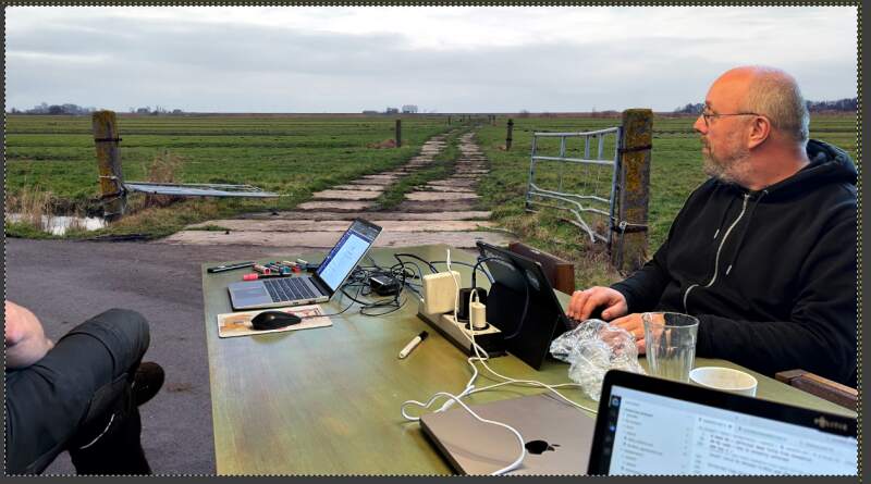
Let's turn on the background.
Pretty good but the colors were wrong. The foreground picture was very yellow from the indoor lighting and the outdoors was a bit dull. An easy fix is to use "auto levels" by selecting a layer and using Colors, Levels and the tiny Auto Input Levels button in lower-left. This applies some magic and works pretty well.
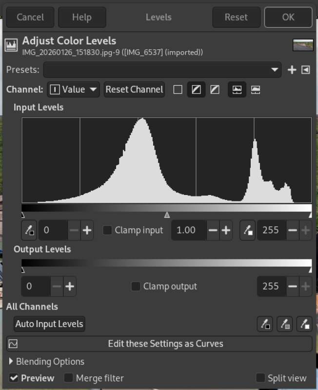
Applied to both layers and we had a winner!
To get a JPEG from this go to File and Export and enter a file
name ending with .jpg. A dialog pops up asking how to compress it
(note JPEG is lossy so this is where we need select our trade-offs).
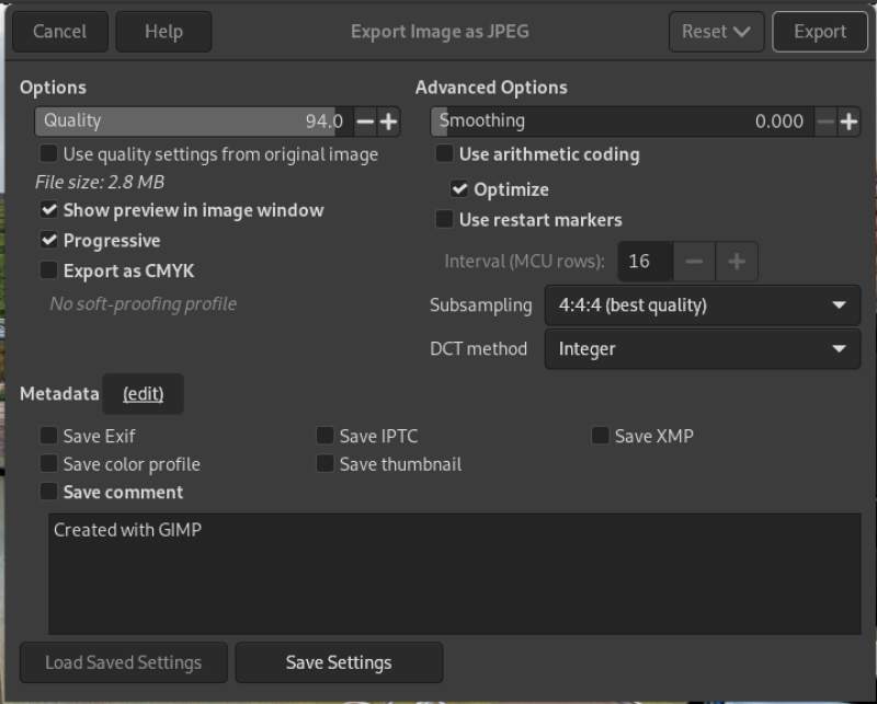
Selecting Show preview in image window allows us to see the
predicted file size and that's too big… We'll scale it down with
ImageMagick's convert command later.
So now we can close Gimp and open a terminal to scale down the image for on this page.
$ identify gimp-collage.jpg
gimp-collage.jpg JPEG 3710x2045 3710x2045+0+0 8-bit sRGB 2.62563MiB 0.000u 0:00.000
$ convert gimp-collage.jpg -scale 800 gimp-collage-scaled.jpg
$ identify gimp-collage-scaled.jpg
gimp-collage-scaled.jpg JPEG 800x441 800x441+0+0 8-bit sRGB 160155B 0.000u 0:00.000
Hmm, 160Kb is still pretty big so let's lower the quality because nobody will notice.
$ convert gimp-collage.jpg -scale 800 -quality 50  gimp-collage-scaled.jpg
$ identify gimp-collage-scaled.jpg
gimp-collage-scaled.jpg JPEG 800x441 800x441+0+0 8-bit sRGB 44146B 0.000u 0:00.000
And here it is:
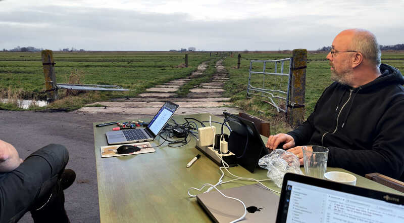
Here's a link to the original export. I will not include the original images or Gimp XCF file here because they are very big.
3.5.1. Conclusion
The Gimp is an awesome application to edit bitmapped pictures but has very little notion of exact sizes and dimensions. You can do parametric and batch operations but within the FabAcademy I'll probably only use it to tweak some photos.
4. Reflection
This was a great week assignment but also a lot of time spend behind my computer. I really look forward to machining stuff in the upcoming weeks.
4.1. Good
4.2. Bad
I spend so much time this week and got very little rest because of it. A lot of time gone into backtracking and starting over a couple of times because I got lost in the application I was working in and was too lost to writing something sensible for this documentation. Nonetheless I am very help with the result.
5. Source Files
Here are the most important source files I created in this week:
