Input Devices
1. Week Assignments
group assignment:
- probe an input device's analog levels and digital signals
individual assignment:
- measure something: add a sensor to a microcontroller board that you have designed and read it
2. Prior Knowledge
I played with a PIR (passive infrared) and a light sensor a long time ago. Both were analog sensors, IIRC.
3. Work!
After a local lecture by Erwin (slides), we experimented with sensors!
3.1. Group Assignment
Christian did a very good job documenting our group assignment for this week.
The (very) short version:
Rain sensor
This sensor came with a electronics kit Christian brought. It is an analog sensor which is less resistive when there's droplets on the board (which is just a row of traces). We tested it with a multimeter but measuring voltage and making it wet.
Temperature and Humidity
It was a DHT11 which can not be tested with a multimeter because it is digital. It emits data from a single digital pin which needs to be decoded. The other two pins are for the power supply (GND and VCC).
To test it we used a library as described here. It reacted to warm breath!
Real Time Clock
Henk provided us with a DS1302 RTC module. We found the datasheet and found out it had a "Simple Serial Port Interface" which isn't SPI but some "Simple 3-Wire Interface".
We use one of the many libaries to read from it successfully and got it to crash by connecting a logic analyzer. Our first attempt of resetting it by taking out the coin cell battery failed, probably due to a capacitor on the board still being changed for the trickle charge.
Distance sensor
Finally we experimented with a ultra sonic distance sensor. Henk experimented with it when he was following the fabacademy source and asked us the reproduce some of his findings. First, we got it to work with this library. Then, we spend a lot of time with the oscilloscope and amplifier chip on the board.
3.2. Individual assignment
3.2.1. DCF77
DCF77 is a German longwave time signal and standard-frequency radio station. It transmits the current Central European (Summer) Time and date. This is very convenience for my final project so I decided I wanted to experiment with it. Thank you Henk and Erwin for bringing this to the table!

The signal is quite simple: every start of a second the transmission dips for 100ms (for a zero) or 200ms (for a one) and in the last second it does not dip.
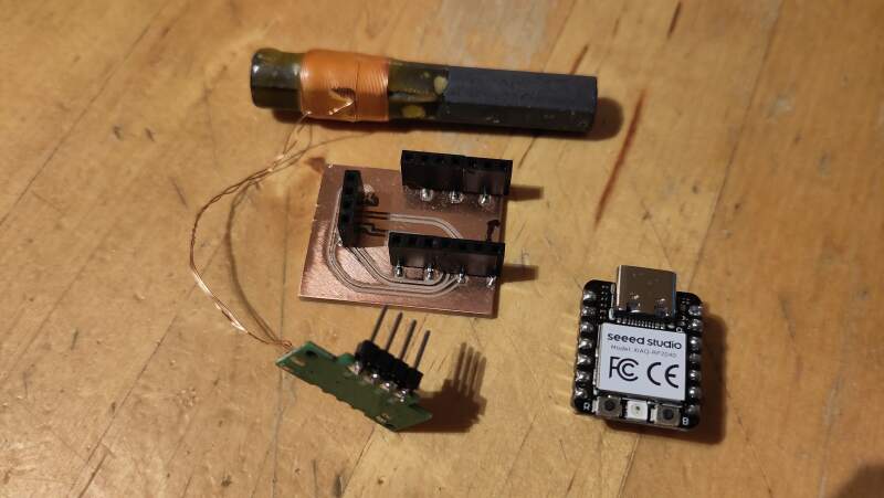
I have the component in the pictures.
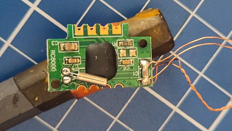
The top of the component is labeled RC8000. I had difficulty finding a datasheet for this component, but I did find the component on AliExpress, which provided some hints in the description.
Technical Specifications
Product number: DCF-3850N-800
RCCM category: DCF/77.5KHz single frequency module
PCBA size: 21.5x13.5x1.0mm/FR4
Antenna size: AP3x8x50mm/High Q
Nominal frequency: 77.5KHz±300Hz
Sensitivity: 28±2dB
Receiving IC: SP6007
- Operating voltage: 1.1…3.3 V
- Current consumption: 85 µA max
- Receiving frequency: 77.5KHz
- Board size (without antenna) LxWxH: 22x13.5x1 mm
- Antenna quality: LxØ: 60x10mm
- Scope of delivery: 1 piece
- DCF receiver module with antenna
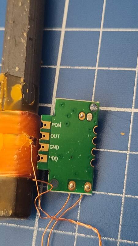
- connect:
- Ground = Pin G
- Operating Voltage = Pin V
- data = pin T
- Power On/Off = Pin P1
- Important note:
- PIN P1 is an on/off switch and must be set to logic low.
| Pin | Function |
|---|---|
| PON | Turn it on and off |
| OUT | Signal |
| GND | Ground |
| VDD | Power |
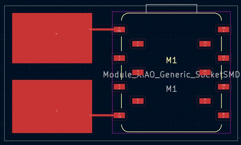
3.2.1.1. Board
I designed a small board in KiCad to connect the DCF77 component to a XIAO RP2040 for experimentation. Since there was no footprint for the DCF77, I used a 4-pin socket and added a rectangle to it to make it obvious which side the board was sticking out.
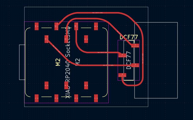
I soldered stacking pins to the component itself to connect to the socket.
3.2.1.2. Code
Using the dsiggi/micropython-dcf77 library, I attempted to get a reading with the following script.
from machine import Pin
from time import sleep_ms
from dcf77 import dcf77

# turn component on
Pin(3, Pin.OUT).value(0)

# start scanning
dcf = dcf77(Pin(4))
dcf.debug(True)
dcf.start()

current_dt = None
while True:
    dt = dcf.get_DateTime()
    if dt != current_dt:
        current_dt = dt
        print(dt)
    sleep_ms(100)
The output indicated issues with pulse widths, which were mostly too long (it should be around 100 or 200 millisecond).
$ curl https://codeberg.org/dsiggi/micropython-dcf77/raw/branch/main/dcf77.py > dcf77.py
$ mpremote cp dcf77.py :dcf77.py
cp dcf77.py :dcf77.py
$ mpremote run dcf77-test1.py
DCF77:  Start decoding
[0, 0, 0, 0, 0, 0, 0, 0]
DCF77:  Wrong pulse width 1588636 - Start new scanning for tick 59
DCF77:  Wrong pulse width 1005 - Start new scanning for tick 59
DCF77:  Wrong pulse width 758 - Start new scanning for tick 59
DCF77:  Detected '1'
DCF77:  Wrong pulse width 15 - Start new scanning for tick 59
DCF77:  Wrong pulse width 811 - Start new scanning for tick 59
DCF77:  Wrong pulse width 979 - Start new scanning for tick 59
DCF77:  Found Tick 59
DCF77:  Wrong pulse width 1937 - Start new scanning for tick 59
DCF77:  Wrong pulse width 816 - Start new scanning for tick 59
DCF77:  Wrong pulse width 36 - Start new scanning for tick 59
DCF77:  Wrong pulse width 9 - Start new scanning for tick 59
DCF77:  Wrong pulse width 802 - Start new scanning for tick 59
It was probably measuring the time the signal was high instead of low.
The library allows setting the detection set to inverted with
dcf.inverted = True, so I tried that.
from machine import Pin
from time import sleep_ms
from dcf77 import dcf77

# turn component on
Pin(3, Pin.OUT).value(0)

# start scanning
dcf = dcf77(Pin(4))
dcf.inverted = True
dcf.debug(True)
dcf.start()

current_dt = None
while True:
    dt = dcf.get_DateTime()
    if dt != current_dt:
        current_dt = dt
        print(dt)
    sleep_ms(100)
This looked better because now it actually "Detected" bits!
$ mpremote run dcf77-test2.py
DCF77:  Start decoding
[0, 0, 0, 0, 0, 0, 0, 0]
DCF77:  Detected '0'
DCF77:  Detected '1'
DCF77:  Wrong pulse width 137 - Start new scanning for tick 59
DCF77:  Wrong pulse width 49 - Start new scanning for tick 59
DCF77:  Detected '0'
DCF77:  Wrong pulse width 13 - Start new scanning for tick 59
DCF77:  Detected '0'
DCF77:  Detected '0'
DCF77:  Signal timeout - Start new scanning for tick 59
DCF77:  Wrong pulse width 133 - Start new scanning for tick 59
DCF77:  Found Tick 59
DCF77:  Wrong pulse width 5 - Start new scanning for tick 59
Unfortunately, after running for an hour, it never received a full minute of bits, so it never produced a proper reading. I connected a a logic analyzer to observe the signal.
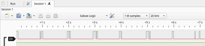
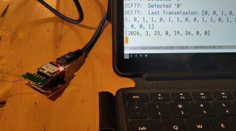
It was clearly visible that there was noise on the line. I was running this on my office desk, surrounded by running electrons, so I moved to the top floor of our house to see if that would help. There, the errors disappeared, and I had finally received a reading!
...
DCF77:  Detected '0'
DCF77:  Detected '0'
DCF77:  Detected '1'
DCF77:  Detected '0'
DCF77:  Last Transmission: [0, 1, 0, 0, 1, 0, 1, 0, 0, 1, 0, 0, 0, 0, 1, 0, 0, 0, 1, 0, 1, 0, 1, 1, 0, 1, 1, 0, 0, 0, 0, 0, 0, 0, 1, 1, 1, 0, 0, 0, 0, 1, 0, 1, 1, 1, 1, 0, 0, 0, 0, 1, 1, 0, 0, 1, 0, 0, 1]
[2026, 3, 21, 5, 20, 35, 0, 0]
DCF77:  Detected '0'
...
Until the washing machine started its spin cycle…
It's a bit disappointing that this component is so sensitive to noise.
However, looking at all the "Wrong pulse" messages and the analyzer
output, I believe this could be fixed in the dcf77 library by
ignoring all the shifts shorter than 50ms. The bit encoding includes
three parity bits and two bits that always have the same value so
after evening out the wave, it's still possible to validate the
reading.
Later, I found an Arduino library that avoids these "squeaks" as describe above: DCF77.cpp line 99
3.2.2. Step response
Neil demostrated step response in the lecture last Thursday, and I realized it would be a great way to implement the snooze function for my final project's alarm function. The examples seemed very simple, so I decided to try it myself.
I found Robert Hart's tutorial in Adrians documentation and opted for the simplest approach possible: just a transmitter and a receiver pin without any resistors.
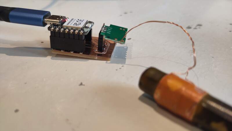
3.2.2.1. Board
I created a very simple board with two pads, one for each pin. To
make KiCad to accept this, I added net labels for TX and RX for
the pins I intended to use. In the PCB editor, I created two pads on
the F.Cu layer, and assigned them to these net labels. Then, they
were easy to wire up.
The result is very basic!
3.2.2.2. Code
In the embedded programming week, we used a QPAD XIAO, and I experimented with some PIO assembly. I skipped that for this week because software can be a dangerous rabbit hole. Instead, I'll use some basic MicroPython.
from machine import Pin, ADC
from time import sleep_ms

rx = ADC(Pin(26, Pin.IN))
tx = Pin(0, Pin.OUT)

def probe():
    result = 0
    for i in range(10):
        tx.value(1)
        high = rx.read_u16()
        sleep_ms(50)
        tx.value(0)
        low = rx.read_u16()
        result = result + (high - low)
    return result

while True:
    print(probe())
The values are all over the place. I'll need to try again with a resistor at some point, to see if I can get more stable values. It's promising nonetheless!
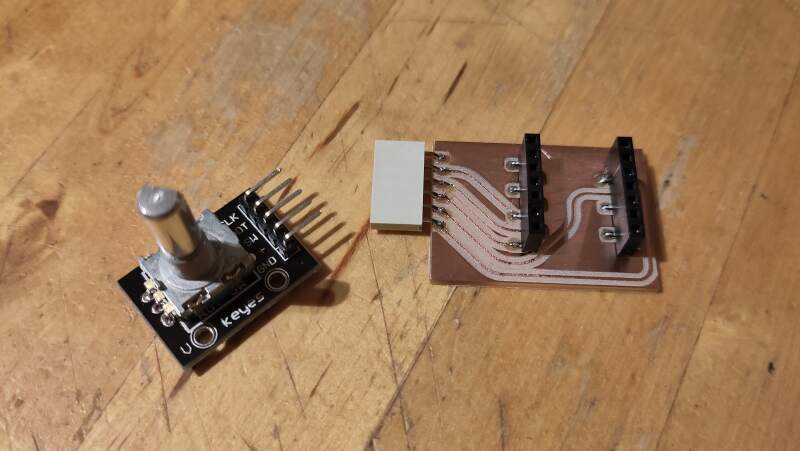
3.2.3. Rotary encoder
I own an Adafruit Macropad. When I came up with the idea to make an alarm clock, one of the first things that I came to mind was using rotary encoders to set the wake-up time, which would provide an awesome user experience!
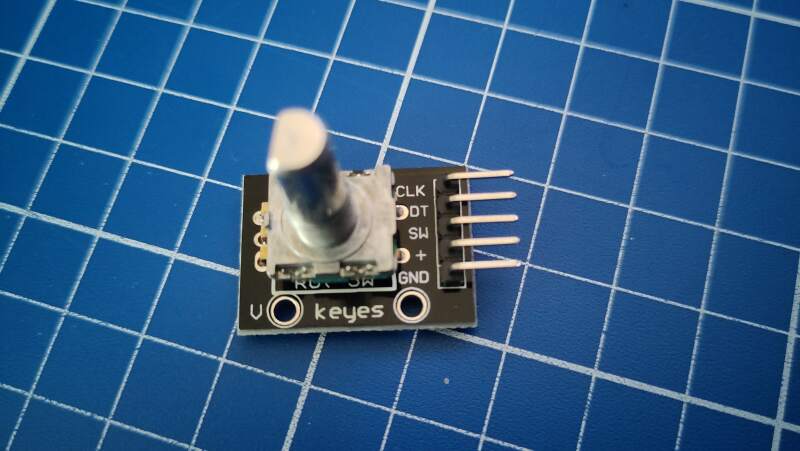
I could't find a datasheet for this component, but I did find a
product page with a lot of information on it. It has 3 output pins
(CLK, DT, and SW) and a ground and power pin (3V3).
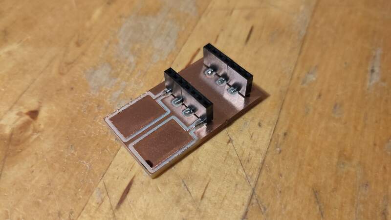
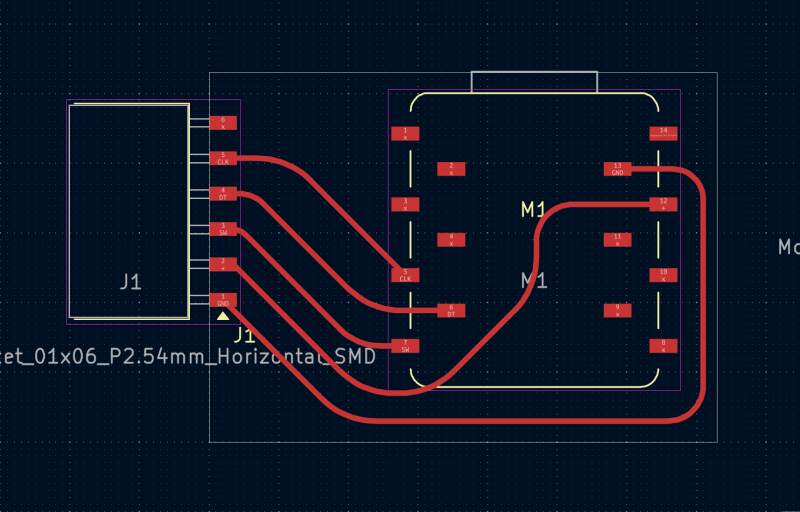
3.2.3.1. Board
I couldn't find a footprint for it in the KiCad library. It has 5 pins spaced like thos on a XIAO (2.54mm), so I used a horizontal 6-pin female header from the fablib to connect it.
I hoked it up as follows:
| Encoder | RP2040 |
|---|---|
| CLK | P6 |
| DT | P7 |
| SW | P0 |
| + | 3V3 |
| GND | GND |
I had some trouble milling this board. In my first attempt half of the trace areas were only scratched instead of all the way through the copper layer (see figure 12). The bed screw on the right was too tight, causing the bed to wrap.
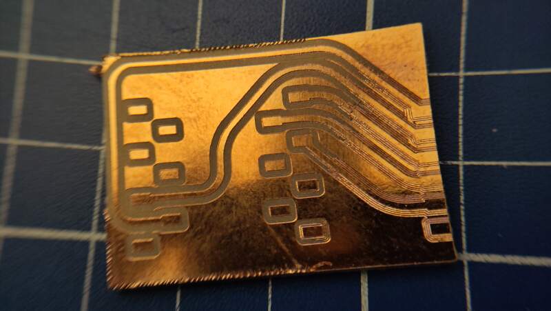
On the second attempt, all the trace areas were just scratched. Henk fixed this by z-leveling with some pressure on the bed, allowing the milling bit to stick out of the collet a bit further.
3.2.3.2. Code
I wrote the code below to observe the pins behavior.
from machine import Pin

clk = Pin(6, Pin.IN)
dt = Pin(7, Pin.IN)
sw = Pin(0, Pin.IN, Pin.PULL_UP)

current_value = [clk.value(), dt.value(), sw.value()]
while True:
    new_value = [clk.value(), dt.value(), sw.value()]
    if new_value != current_value:
        print(new_value)

    current_value = new_value
Note: I used the internal pull-up resistor on the sw because
otherwise, it doesn't detect the knob presses. Without the pull-up,
it does jitters when I touch it, so I guess: extra points for a touch
sensor!
Turning it clockwise, I observed the following bursts per click:
[0, 1, 1]
[0, 0, 1]
[1, 0, 1]
[1, 1, 1]
Turning counter-clockwise:
[1, 0, 1]
[0, 0, 1]
[0, 1, 1]
[1, 1, 1]
And pressing the knob changes the last value to 0.
The changes in values above correspond to the description of Incremental Encoders on Wikipedia, but in the opposite direction.
To detect the direction, I can assume:
- Clockwise: when
clkgoes from low to high and thedtis low. - Counter-Clockwise: when
clkgoes from low to high and thedtis high.
from machine import Pin

clk = Pin(6, Pin.IN)
dt = Pin(7, Pin.IN)
sw = Pin(0, Pin.IN, Pin.PULL_UP)

direction = 0
current_count = count = 0
current_value = [clk.value(), dt.value(), sw.value()]
while True:
    new_value = [clk.value(), dt.value(), sw.value()]

    if new_value != current_value:
        if new_value[0] != current_value[0] and new_value[0] == 1:
            direction = dt.value()

            if direction == 0:
                count = count + 1
                print("clockwise", count)
            else:
                count = count - 1
                print("counter-clockwise", count)

        if new_value[2] == 0: # button pressed?
            count = 0
            print("button", count)

        current_count = count
        current_value = new_value
Note: The above code is for testing purposes only. It's a very busy loop that continuously polls the pin values. This approach is not suitable for production and would likely require debouncing code.
4. Reflection
I had a fun week and accomplished more than I initially expected.
4.1. Good
4.2. Bad
5. Source Files
DCF77
KiCad:
Code:
Step Response
KiCad:
Code:
Rotary Encoder
KiCad:
Code:
