Mechanical / Machine Design
1. Week Assignments
group assignment:
- actuate and automate your machine
- document the group project and your individual contribution
- prepare a demonstration of your machines for the next class
See also: group page
2. Prior Knowledge
I loved my LEGO Technic sets as a kid and even built an RC car using the LEGO Mindstorms set of my two sons. That's the extent of my experience. I look forward to applying my Fab Academy knowledge to a machine!
3. Work!
Space poffer? Pancake machine? A baking machine.
3.1. Design
General components:
- Batter dispensing
- Transport
- Heating
- Stardust dispensing (icing sugar)
There are plenty of parts available in the lab (in the "project graveyard") to build the above components, but some needed to be sourced elsewhere. We visited a cheap dump store to hunt for parts and found a baking tray for tiny donuts, which was very inexpensive, so we took it for experimentation. Christian bought a small panini press at a thrift store, and Heleen found a large funnel at a hardware store.
- Hopper / large funnel
- to hold batter
- Metal containers / pans
- to bake batter in
- Sandwich toaster / panini press
- to apply heat
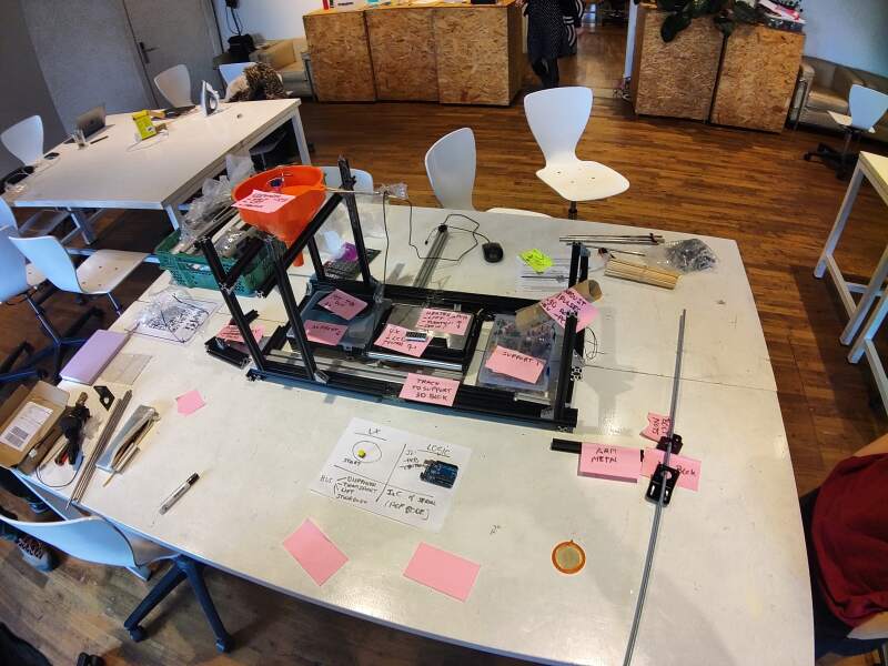
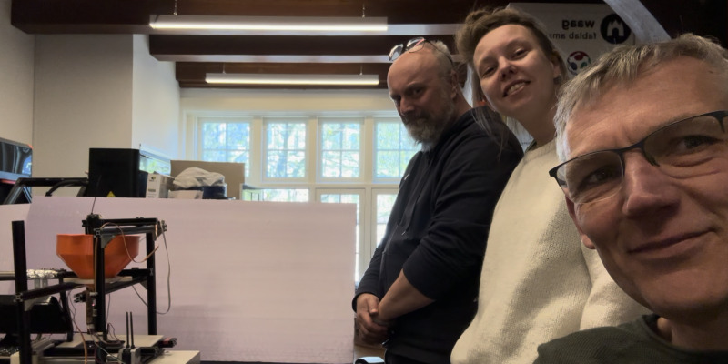
After much debate, we came up with a general layout for the machine and used aluminium extrusion parts to build the machine frame. Using this, we acted out the process and filmed it.
For the electronics design, we decided to make PCBs with a microcontroller for each component separately, having them communicate through I²C. A central unit would send commands to all the sub-components: move to batter, dispense batter, move to toaster, close toaster lid, open toaster lid, move to sugar dispenser, etc.
3.2. Planning
With a clear picture of what we wanted to build, we identified the first general parts (batter, transport, and heating) as the minimal viable product (MVP). Each of us took responsibility for a part. I was responsible for transport, Heleen for batter, and Christian for heating and the controller.
3.3. Build
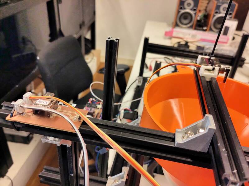
For the transport, I opted for a box sliding over a length of aluminium extrusion using a threaded rod and a stepper motor. I would measure the number of turns it takes to traverse the entire length of the frame and use that to calculate the turns needed to reach the batter, toaster, and dispenser stations. A switch at the start of the track would be used to detect when the stepper is at position 0.
3.3.1. Mechanics
For the transport mechanics, I acquired:
- A stepper motor
- A threaded rod
- A connector to couple the stepper with the rod
- Nuts to match the rod
- A switch to detect the start position
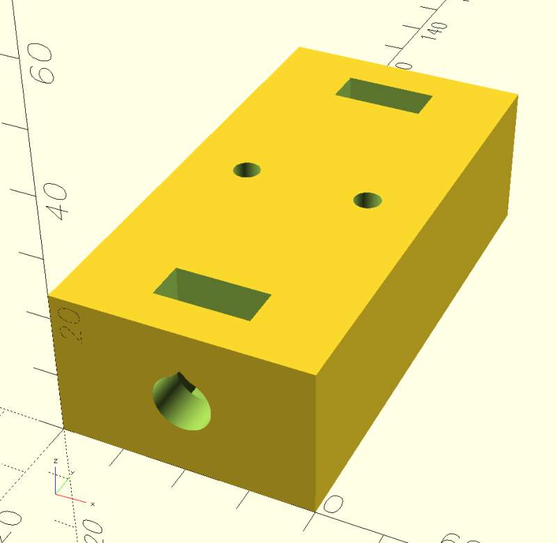
First, I designed and 3D printed a box with a hole to hold the nuts in place, to see if that would create the sliding motion I had in mind. It took a couple of iterations to get the guiding nuts to fit properly. I ended up embedding smaller nuts within the print (see top of the model in figure 3) by pausing the print and dropping them in. These allow attaching an arm to the carriage, which should push the pans.
Adjusting the base frame and adding bars to attach parts, we discovered that although the extrusion parts look similar, their slots varied slightly, making it difficult to find combinations that actually fit.
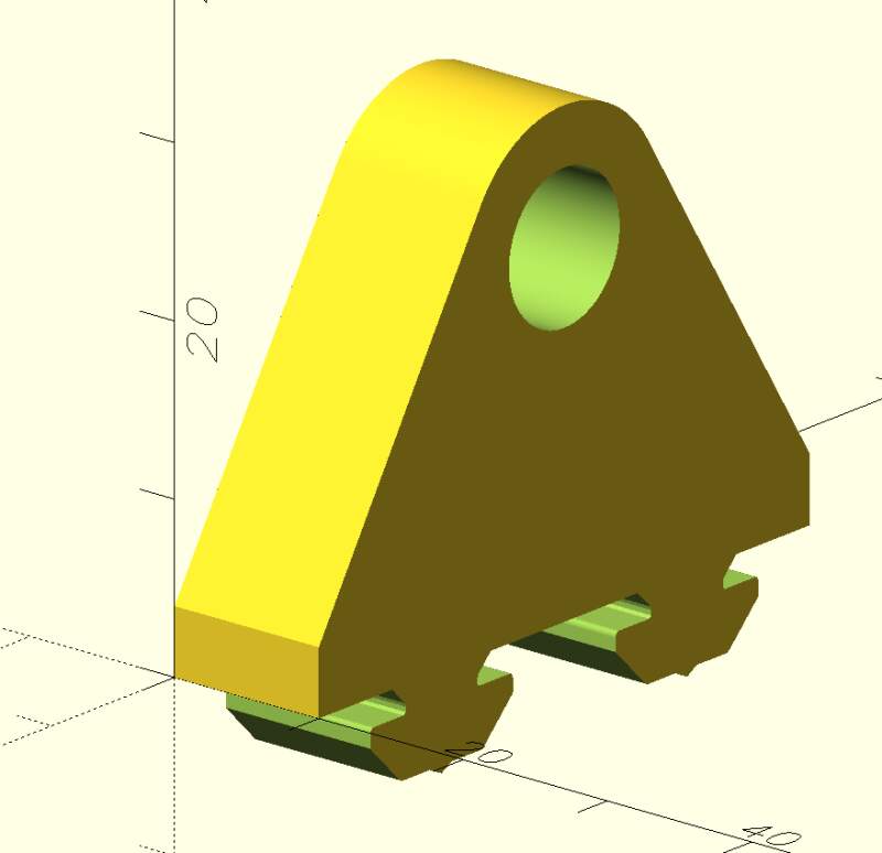
Next, I started modeling a part to attach the stepper motor to the frame. However, I realized it would be more effective to design smaller parts to slide on the extrusions so we could use zip ties.
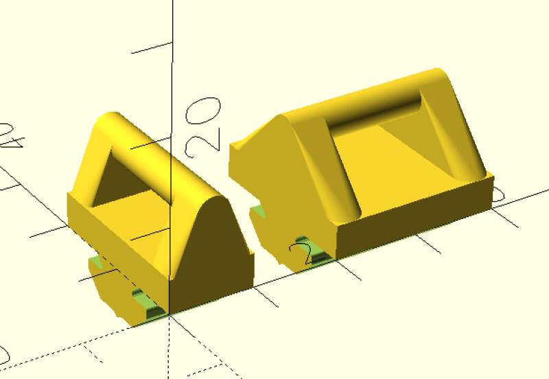
I created the above by downloading a step-file from the aluminium
extrusion product page, converting it to an stl-file in FreeCAD
(because OpenSCAD does not support step-files), and using that to
subtract from a foot print. Well, it was a slightly fatter version I
created using the minkowski function.
For the end of the rail, I created a simple stop to hold the rod in its place using the same footprint trick to make it attachable to the rail.
3.3.2. Electronics
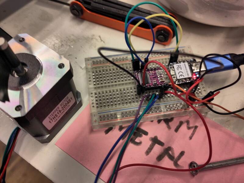
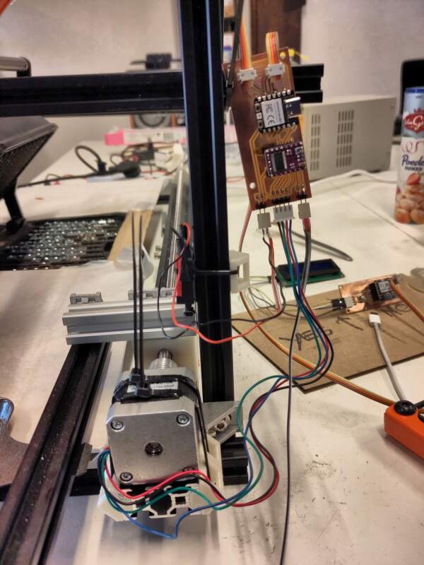
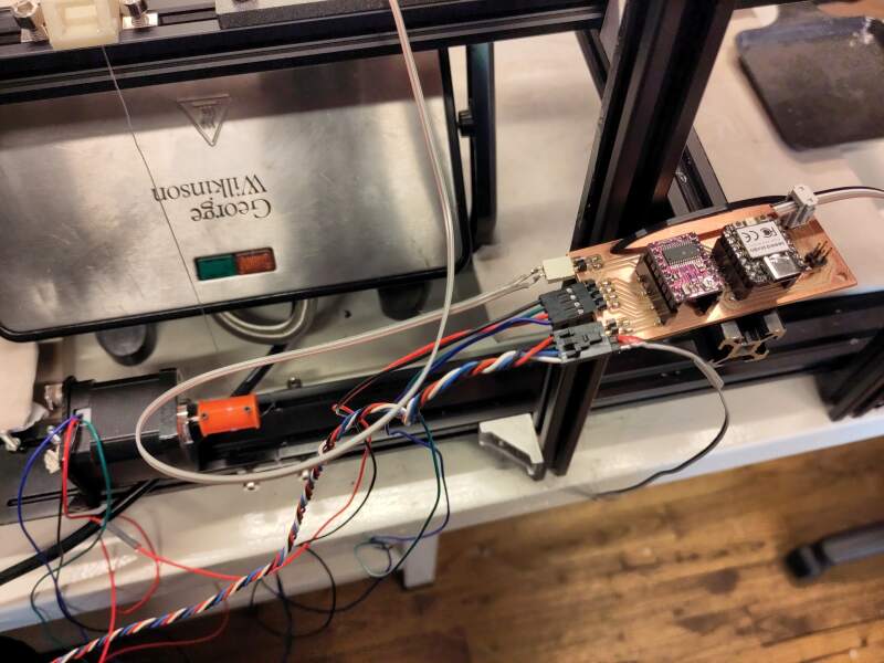
With the mechanics (literally) tied down on the frame, it was time to work on the electronics. First, I reproduced the stepper motor experiment we did as a group in week 10 on a breadboard: an RP2040, a Pololu DRV8825 Stepper Motor Driver, a stepper motor, a workbench power supply, and drv8825.py.
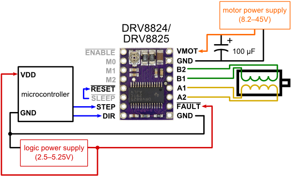
The motor was very noisy. Increasing the step frequency from 200Hz to 1kHz helped, but then it started skipping. I used Leo's and Henk's documentation to try and set the current limit on the driver board but could not get it stable. Following the video on the Pololu product page to adjust the current using the potentiometer (trimmer) on the board. According to the video, I should adjust the trimmer until I read 1V over two pads on the board using a multimeter, but I only read 12V. Frustrated, I started swapping out parts to see if that helped. I ended up using a lighter stepper motor which ran smoothly.
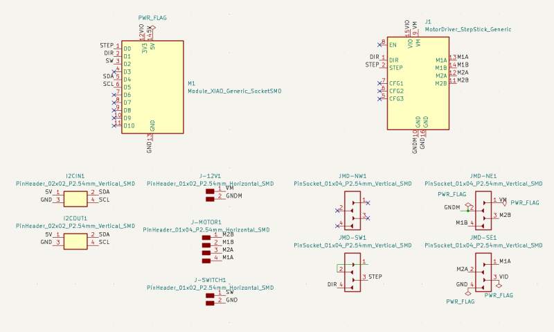
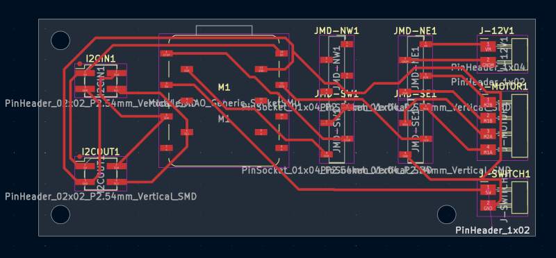
With it stable, I started designing a PCB to hookup everything, including a switch and connectors for I²C. The stepper driver is already on a PCB with stacking pins soldered onto it. Unfortunately, there is no "socket" for this in the FabLib, but there is a through-hole footprint. I used that to carefully place pin sockets on the PCB for fitting the driver board onto our board. This does violate some design rules because the pin sockets are very close together and they seem to overlap, but (like the XIAO socket footprint) they do not in practice.
3.3.3. Software
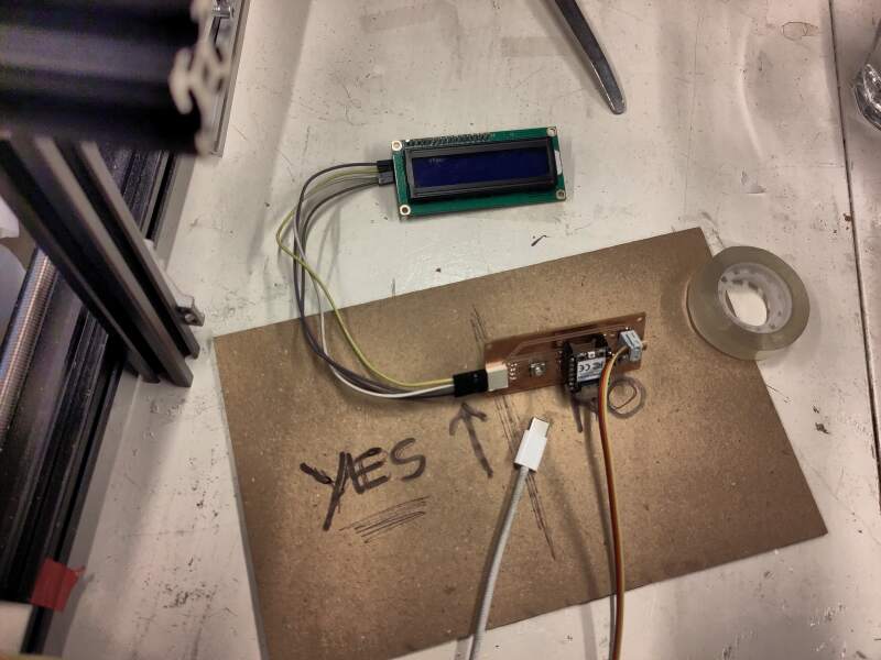
The first thing I implemented was homing: the carriage needs to run back to the start point, which is detected by pressing a switch. The driver library I used allows sending commands to the stepper, such as "take 200 steps" (a full revolution), and returns immediately (it uses a hardware timer to run the motor).
I allowed stopping the motor under certain conditions (switch pressed, in our case) by changing the library to add a callback in the timer event handler to allow the code to stop the motor. Below is the change I made:
--- drv8825.orig.py
+++ drv8825.py
@@ -87,6 +87,7 @@
                  microstep_pins=None,
                  sleep_pin=None,
                  reset_pin=None,
+                 timer_callback=None,
                  timer_id=-1,
                  steps_per_revolution=200):
         """
@@ -99,6 +100,7 @@
         <timer_id>  (number) timer to use for step timing, the default
                     value -1 (last timer) usually works on most boards
         <steps_per_revolution> (number) Full steps for 360 degrees revolution
+        <timer_callback> (function) called at the start of the internal timer callback
         Notes: - <step_pin> is mandatory.
                - other pins are optional (presumably fixed wired)
                - instances of DRV8825 are started enabled.
@@ -126,6 +128,10 @@
         self._actual_pos = 0                    # actual position
         self._target_pos = 0                    # target position

+        self.timer_callback = None
+        if timer_callback is not None:
+            self.timer_callback = timer_callback
+
     def enable(self):
         """ Enable the DRV8825
             When pins for sleep and reset are not specified
@@ -169,6 +175,9 @@
         self._timer.deinit()                    # (running or not)
         self._timer_running = False

+    def is_running(self):
+        return self._timer_running == True
+
     def resolution(self, microsteps=1):
         """ method to set step number of microsteps per full step
             <microsteps> supported values: 1,2,4,8,16,32
@@ -195,14 +204,22 @@
             self._actual_pos -= 1
             self._step_pin.off()

+    def set_timer_callback(self, f):
+        self.timer_callback = f
+
     def _timer_callback(self, t):
         """ determine if stepping action opportune
             if true perform one step forward or backward
         """
-        if self._free_run_mode != 0:
-            self.one_step(1 if self._free_run_mode > 0 else -1)
-        elif self._target_pos != self._actual_pos:  # target not reached yet
-            self.one_step(1 if self._target_pos > self._actual_pos else -1)
+
+        if self.timer_callback is not None:
+            self.timer_callback(self)
+
+        if self._timer_running == True: # not stopped by timer_callback
+            if self._free_run_mode != 0:
+                self.one_step(1 if self._free_run_mode > 0 else -1)
+            elif self._target_pos != self._actual_pos:  # target not reached yet
+                self.one_step(1 if self._target_pos > self._actual_pos else -1)

     def steps(self, steps, microsteps=1, stepfreq=200):
         """  move stepper motor a number of steps:
With the above changes in place, I implemented the home function
which runs the carriage backward until the switch is pressed and then
forward until it is released. At the start point, it sets the global
variable stepper_position to 0.
stepper_position = None

def stop_on_sw_0(stepper):
    if home_sw.value() == 0:
        stepper.stop()

def stop_on_sw_1(stepper):
    if home_sw.value() == 1:
        stepper.stop()

def wait_until_stepper_done(stepper):
    while stepper.is_running():
        sleep_ms(100)

def home():
    global stepper_position

    stepper = DRV8825(PIN_STEP, direction_pin=PIN_DIR, timer_callback=stop_on_sw_0)
    stepper.freerun(stepfreq=-1000)
    wait_until_stepper_done(stepper)

    stepper = DRV8825(PIN_STEP, direction_pin=PIN_DIR, timer_callback=stop_on_sw_1)
    stepper.freerun(stepfreq=1000)
    wait_until_stepper_done(stepper)

    stepper_position = 0
I ran it to the end of the track, keeping track of the steps. I found
it takes roughly 96880 steps for 600mm. This allowed me to write a
goto function.
TRACK_LENGTH_STEPS = 96880
TRACK_LENGTH_MM = 600
STEPS_PER_MM = int(TRACK_LENGTH_STEPS / TRACK_LENGTH_MM)

def goto(position_in_mm):
    global stepper_position
    new_position = STEPS_PER_MM * position_in_mm

    if stepper_position is None:
        home()

    steps = new_position - stepper_position
    stepper = DRV8825(PIN_STEP, direction_pin=PIN_DIR)
    stepper.steps(steps, stepfreq=1000)
    wait_until_stepper_done(stepper)

    stepper_position = new_position
3.3.3.1. I²C
Unfortunately, the MicroPython standard libraries do not implement I²C secondary mode out of the box, only primary. However, multiple implementations can be found online. I tried four of them and only got one to actually work: TraoreMorike/Raspberry-Pico—I2C-Slave.
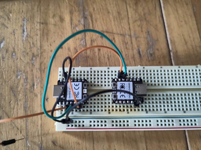
Using a test implementation of the controller by Christian1, 2, I managed to receive "STATUS" commands and respond with 42 using the following:
from RP2040_Slave import i2c_slave

I2C_ADDR = 8

i2c = i2c_slave(i2cID=1, sda=6, scl=7, slaveAddress=I2C_ADDR)

try:
    received = ''
    response = 42

    while True:
        state = i2c.handle_event()

        if state == i2c.I2CStateMachine.I2C_START:
            pass

        if state == i2c.I2CStateMachine.I2C_RECEIVE:
            while (i2c.Available()):
                received += chr(i2c.Read_Data_Received())

        if state == i2c.I2CStateMachine.I2C_REQUEST:
            while (i2c.is_Master_Req_Read()):
                i2c.Slave_Write_Data(response)

        if state == i2c.I2CStateMachine.I2C_FINISH:
            print("received:", received)
            print("response:", response)
            print()

            received = ''

finally:
    # need this to release pins when script is stopped
    i2c.deinit()
For reference, the implementations I tried but could not get to work:
3.3.3.2. Async stepper
The I²C protocol requires the secondary to respond immediately to a
request from the primary; otherwise, it causes timeout problems in the
controller. This makes it impossible to wait for the stepper to
finish its job because it takes too long. So, we need to drop the
wait_until_stepper_done function and switch to a full callback
driving approach to control the stepper, with a main loop to handle
the I²C communication.
First, we'll rewrite the goto part to use the callback function.
def handle_goto(stepper, target, new_position):
    global stepper_position
    if stepper.get_progress() == target:
        stepper.stop() # why do I need to do this?
        stepper_position = new_position

def goto(new_position):
    if new_position > TRACK_LENGTH_STEPS:
        new_position = TRACK_LENGTH_STEPS

    target = new_position - stepper_position
    stepper.set_timer_callback(lambda s, t=target, p=new_position: handle_goto(s, t, p))
    stepper.steps(target, stepfreq=1000)
    return new_position
But we still want to go "home" when the microcontroller starts up.
# go home on startup
home()
while stepper.is_running():
    sleep_ms(500)
Next, we needed the I²C main loop.
from RP2040_Slave import i2c_slave

i2c = i2c_slave(i2cID=1, sda=6, scl=7, slaveAddress=8)

POSITION_PAN1_BATTER = 150 * STEPS_PER_MM
POSITION_PAN2_BATTER = 290 * STEPS_PER_MM
POSITION_PANS_IN_HEATER = 390 * STEPS_PER_MM
POSITION_PANS_UNDER_DISPENSER = TRACK_LENGTH_MM * STEPS_PER_MM
POSITION_PANS_SERVE = TRACK_LENGTH_MM * STEPS_PER_MM

COMMAND_READY = "READY"
COMMAND_PAN1_BATTER = "POSITION-PAN1"
COMMAND_PAN2_BATTER = "POSITION-PAN2"
COMMAND_PANS_IN_HEATER = "POSITION-PANS-IN-HEATER"
COMMAND_PANS_UNDER_DISPENSER = "POSITION-PANS-UNDER-DISPENSER"
COMMAND_PANS_SERVE = "POSITION-PANS-SERVE"

RESPONSE_UNKNOWN=0
RESPONSE_PAN1_BATTER=20
RESPONSE_PAN2_BATTER=22
RESPONSE_PANS_IN_HEATER=31
RESPONSE_PANS_UNDER_DISPENSER=41
RESPONSE_PANS_SERVE=44 # ??

COMMANDS = {
    "STATUS": (POSITION_PAN1_BATTER, RESPONSE_PAN1_BATTER),
    COMMAND_PAN1_BATTER: (POSITION_PAN1_BATTER, RESPONSE_PAN1_BATTER),
    COMMAND_PAN2_BATTER: (POSITION_PAN2_BATTER, RESPONSE_PAN2_BATTER),
    COMMAND_PANS_IN_HEATER: (POSITION_PANS_IN_HEATER, RESPONSE_PANS_IN_HEATER),
    COMMAND_PANS_UNDER_DISPENSER: (POSITION_PANS_UNDER_DISPENSER, RESPONSE_PANS_UNDER_DISPENSER),
    COMMAND_PANS_SERVE: (POSITION_PANS_SERVE, RESPONSE_PANS_SERVE)
}

current_command = None

def handle_command(command):
    global current_command

    pos, res = COMMANDS.get(command) or (None, None)
    if pos is not None and not stepper.is_running():
        print("new command", command, (pos, res))
        current_command = command
        goto(pos)

    pos, res = COMMANDS.get(current_command) or (None, None)
    if pos is not None and pos == stepper_position:
        print("response", res)
        current_command = None
        return res

    return RESPONSE_UNKNOWN

try:
    command = ''
    response = 0

    while True:
        state = i2c.handle_event()

        if state == i2c.I2CStateMachine.I2C_START:
            pass

        if state == i2c.I2CStateMachine.I2C_RECEIVE:
            while (i2c.Available()):
                command += chr(i2c.Read_Data_Received())

        if state == i2c.I2CStateMachine.I2C_REQUEST:
            while (i2c.is_Master_Req_Read()):
                i2c.Slave_Write_Data(response)

        if state == i2c.I2CStateMachine.I2C_FINISH:
            response = handle_command(command)
            command = '' # clear command for next receive

finally:
    # need this to release pins when script is killed
    i2c.deinit()
The above worked very well. Because the program knows its position after finishing a command (do not send it another command until an acknowledgment of finishing the latter command has been received!), it's possible to alternate between positions without returning all the way home (it runs quite slowly and loudly).
3.3.3.3. Time is running out!!
We started to run out of time, so we decided to drop the stardusting (icing sugar) at the end of the baking process.
To save time, we decided I would implement the batter and panini press lifting too, because I already had a secondary component working. There was a lot of tweaking involved, but everything seemed to function relatively quickly. For testing, Chris and I connected all the PCBs to the I²C bus to perform dry runs. This revealed some timeout issues in the controller, but they were fixed quickly, allowing us to proceed.
3.3.4. Finishing up
We connected all the boards to the peripherals and started test runs.
After a lot of tweaks, we settled on 6 seconds of batter dispensing and 20 minutes of baking time. It is far from perfect..
3.3.5. Possible improvements
There are a lot of things we can improve on this machine. Here are a few:
- Add the sugar dispenser.
- Find a better recipe for combinations of amount of batter and time in the heater.
Better threaded rod for the transport component.
We used a bent rod with a construction (sharp, narrow threads meant for grip) instead of a motor function (wider, more angled threads meant for displacement). This made the transport really wobbly and slow.
- Better system integration, such as housing for the electronics and proper connectors for the 12V power supply.
- Make it prettier by providing some kind of housing from triplex and vinyl cutting some decorative / funny elements on it.
4. Reflection
I loved that I could apply nearly all the things I learned this Fab Academy! But, to be honest, I mostly hated these two weeks. The working together part was.. fun and horrible at the same time.
4.1. Good
4.2. Bad
4.3. Ugly
5. Source Files
3D models:
holder.scad (zip tie holders)
Relies on:
- Aluminium slot profile 2020 V-slot.stl (aluminium extrusion converted to stl-file)
- rail-bold.scad (bolder version of aluminium extrusion for subtraction)
- transport.scad (carriage)
- transport_stop.scad (carriage stop)
Initial code stepper:
- drv8825.py (patched version of robhamerling/micropython-drv8825)
- stepper.py
KiCad model for stepper motor PCB:
Base of the I²C code:
- RP2040_Slave.py (source at TraoreMorike/Raspberry-Pico—I2C-Slave)
- RP2040_I2C_Registers.py (source at TraoreMorike/Raspberry-Pico—I2C-Slave)
- RP2040_Slave_test.py
Code secondary components:
Footnotes:
Later I tried using an I²C primary written in MicroPython but could not get it to communicate with the secondary, but I never figured out why. Here's the not working code for reference: controller.py.
