Output Devices
1. Week Assignments
group assignment:
- measure the power consumption of an output device
individual assignment:
- add an output device to a microcontroller board you've designed, and program it to do something
2. Prior Knowledge
Apart from what I have learned in the last weeks, I had an Arduino kit years ago and blinked lights and a 8x8 LED matrix.
3. Work!
We had a short local lecture by Erwin this week discussing various types of output devices (his slides). My general impression is that, where input devices are about sensitivity, output devices are about power. Many of these devices require extra power to operate. What I missed in the lectures is how to you manage circuits where components have different power requirements.
3.1. Group Assignment
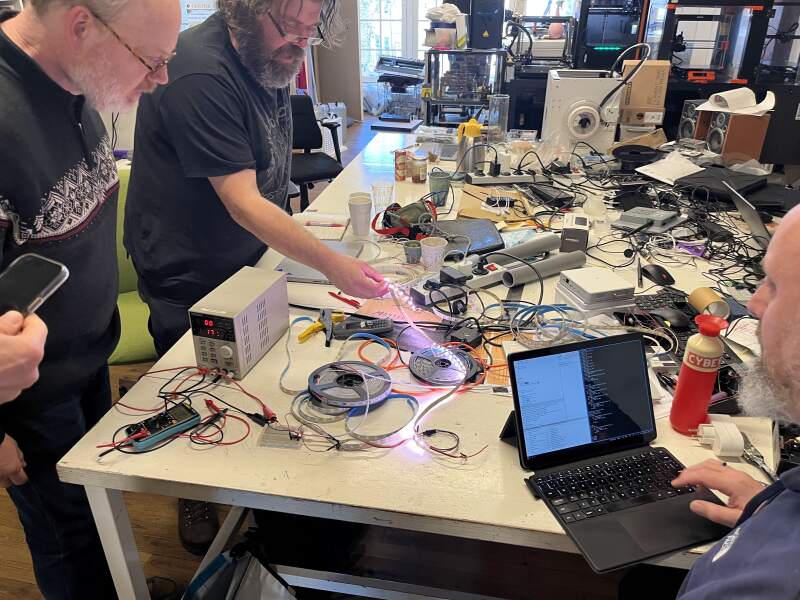
For the group assignment, we used a bench power supply to drive and measure output devices. I learned: you set either the current or the voltage on the power supply and it will try to keep that constant. That way, you can see the voltage or current change when a circuit changes its power demands.
3.1.1. Addressable LEDs
We started with a NeoPixel strip. The ground and power were hooked up to the power supply, and a XIAO RP2040 was used to drive it using the following strip:
import machine, neopixel

PIN = 0

def aan(n, c):
    np = neopixel.NeoPixel(machine.Pin(PIN), n)
    for i in range(n):
        np[i] = c
    np.write()

aan(10, (255, 255, 255))
We varied the amount of LEDs, the color, and the intensity. As expected: more LEDs mean more power is drawn. Slightly more interesting: the LEDs still draw power when turned off (to power the LED controllers handling the WS2812B protocol), and the different colors draw different amounts of power.
3.1.2. Stepper Motor
Next, we tried to run a stepper motor using a DRV8825 stepper driver carrier. We hooked up the driver carrier to a XIAO RP2040 (see figure 1), and used this library and the MicroPython REPL to get it turn.
$ mpremote cp drv8825.py :drv8825.py
$ mpremote
>>> import drv8825
>>> drv = drv8825.DRV8825(0)
>>> drv.steps(10)
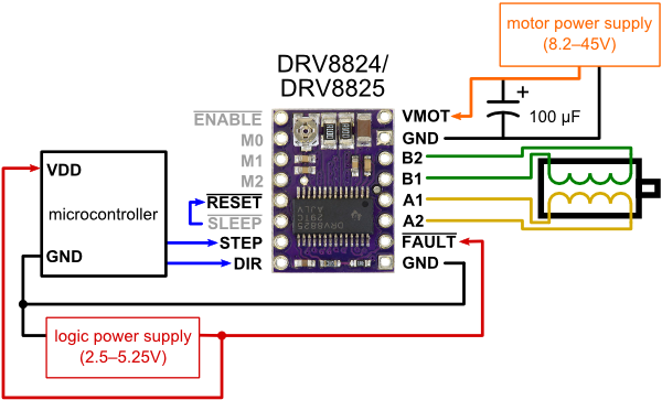
At first nothing happened. Then we notice the RESET and SLEEP
pins should be connected for the setup. After connecting them the
motor buzzed when issueing drv.steps(10) commands. We were supply 5
volts, it rotated after setting the power supply to 12 volts.
I forgot to take any pictures. For a better report see Christians stepper motor documentation.
3.2. Individual Assignment
For my final project, I need to display time and sound an alarm, so the outputs are obvious.
3.2.1. Display
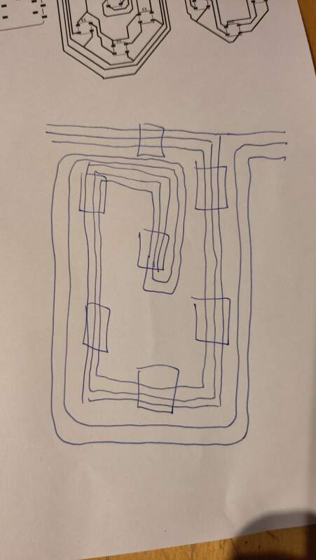
While experimenting with the NeoPixels in the group assignment I realized: I do not need to go charlieplexing all those LEDs when I use seven-segment digits. I was expecting to spend the whole weekend trying to get the traces right for 4 digits with the minimal amount of 0Ω bridges or vias in KiCad. But using NeoPixels I can just go for the one pin solution!
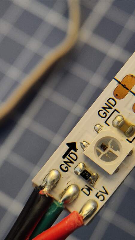
To get to know NeoPixels better, I brought a 125cm strip home from the Waag for experimentation. Two things are notable when examining it:
- The first node has a 27Ω resistor.
- All nodes have a capacitor.
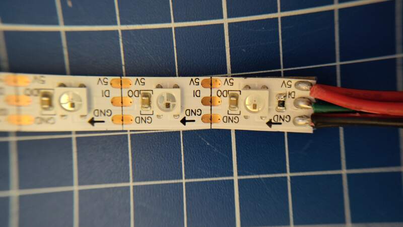
The strip does not have any markings, but browsing the addressable LED items in the fab inventor and an article about LEDs on the Seeed site, I noticed the LED components on the strip are very similar to the "Adafruit Industries LLC 3094" components. I am pretty sure they are WS2812B (or APA104?) LEDs (datasheet).
Some fun with the LEDs:
import machine, neopixel, time

PIN = 0
N_OF_LEDS = 60
COLOR = (100, 100, 100)
SPEED = 20

np = neopixel.NeoPixel(machine.Pin(PIN), N_OF_LEDS)

def all_off(np):
    for i in range(N_OF_LEDS):
        np[i] = (0, 0, 0)

all_off(np)
np.write()
def maybe_on(np, i, c):
    if i >= 0 and i < N_OF_LEDS:
        np[i] = c

def one_on(np, i, c):
    np[i] = c
    maybe_on(np, i - 1, (0, 0, 0))
    maybe_on(np, i + 1, (0, 0, 0))

while True:
    for i in range(N_OF_LEDS):
        one_on(np, i, COLOR)
        np.write()
        time.sleep_ms(SPEED)

    for i in range(N_OF_LEDS - 1, -1, -1):
        one_on(np, i, COLOR)
        np.write()
        time.sleep_ms(SPEED)
3.2.1.1. Digits
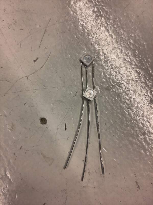
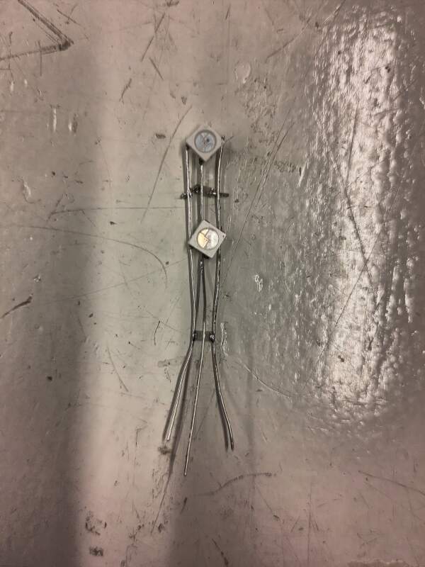
To figure out if I could use the LED by itself without the strip, I desoldered one and soldered jumper wires to the VDD, VSS, and DIN pins.
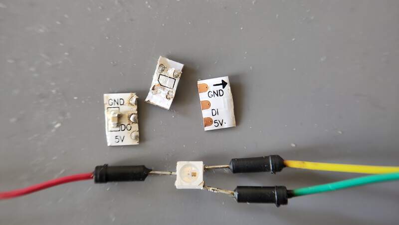
It was a challenge to do this, and part of the packaging got melted, but it still worked, albeit a bit unreliably. With the hunch that I could get this to work without resistors and capacitors, I decided I would make digit components that could be connected in series, just like a NeoPixel strip but for digits.
Happy about the result I asked Henk on Mattermost if these LEDs would be available in the lab, but he told me they might not be in stock. So, to ensure I had something to work on, I decided to also make schematics for NeoPixels cut from the strip (because desoldering is too error prone).
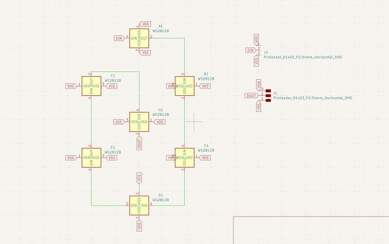
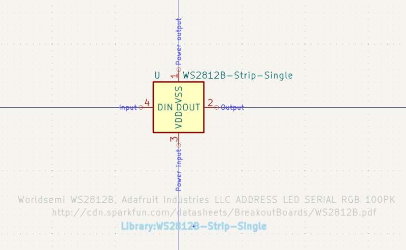
I created a new symbol in the KiCad Symbol Editor.
Then I created a footprint in the KiCad Footprint Editor.
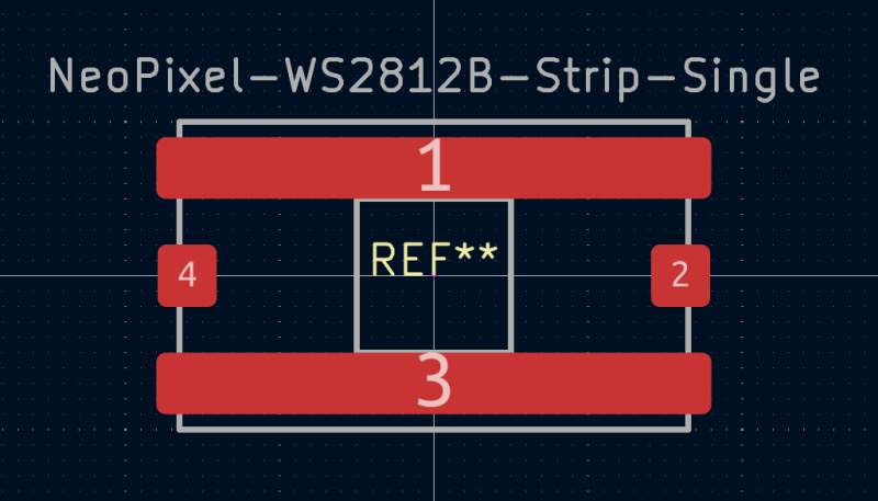
Note: pin 1 (VSS) and pin 3 (VDD) are physically connected (I checked with a multimeter), so I drew them as one big pin.
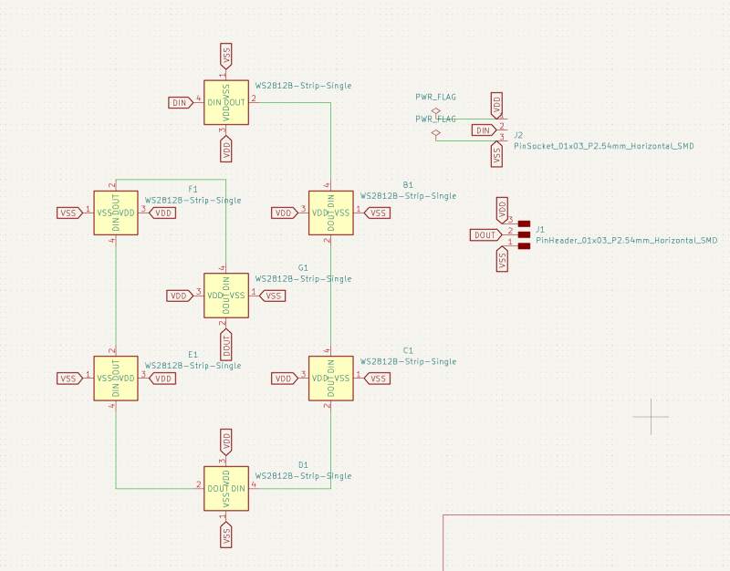
I recreated the schematics using the new symbol.
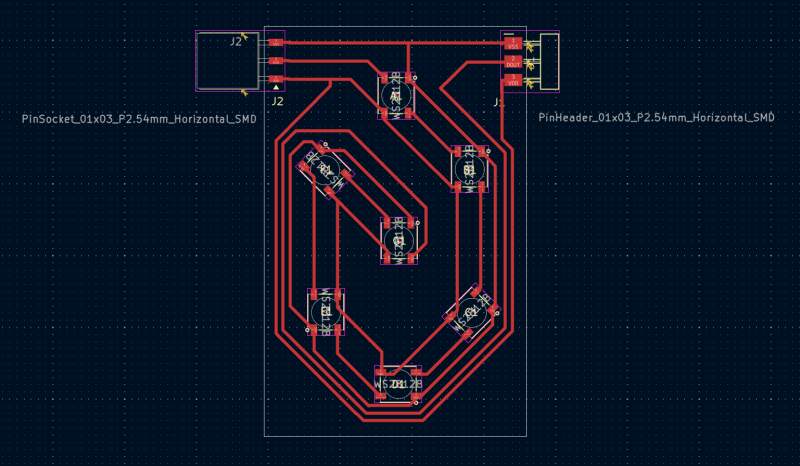
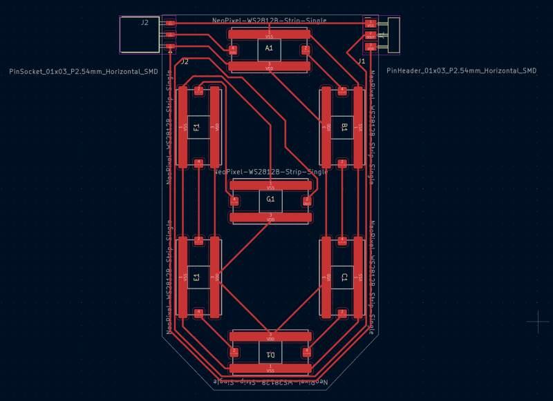
And recreated the PCB from the new schematics.
The next day at the Waag, I discovered there were still some WS2812B LEDs in stock, so that was an interesting lesson in making symbols and footprints.
3.2.1.2. Milling
Milling my first design went badly. The traces were too close together, and Mods fused them. I did not notice at first, but as I was showing off to Henk, he noticed it immediately.
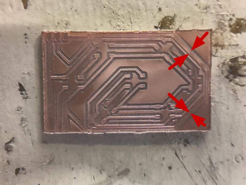
Henk also reminded me that this had happened to me before (did I miss this documenting?). So, I decided to pull up the PCB Design Rules.
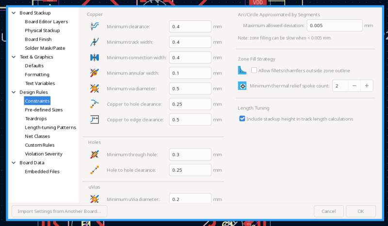
Apparently, setting the Minimum Clearance to 0.4 with a 0.4 mill
in Mods is asking for trouble. I changed the Minimum Clearance to
0.6, adjusted the PCB design to pass the rules and reran Mods. The
preview look good and the milled PCB came out perfect.
After soldering the first LED (and the pin header), I tested it, and it worked. Then I soldered the second LED, but the second LED would not light up. I added the capacitors as shown in the datasheet (I was expecting I could do without).
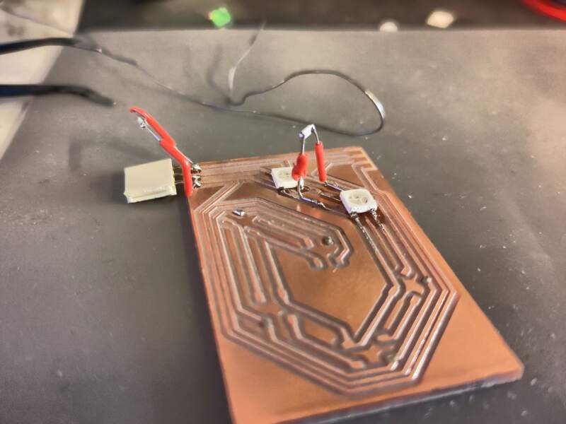
But that did not work. I removed the second LED; the first still worked. Henk resoldered the second LED; it still did not work. I replaced the second LED with a new one; nope.
Because the PCB was looking worse with every iteration, I tried to solder the LEDs without a PCB to see if it would even work.
Same problem.
I even added the capacitors:
No show. Stunned, stressed, hungry, and irritated.
Then (local instructor) Leo entered the lab. He gave some advice, none of which was fruitful, but then I realized the code I wrote to test the first LED did not activate the second LED..
F**K!
I changed the code, and the second LED on the butchered PCB lit up.
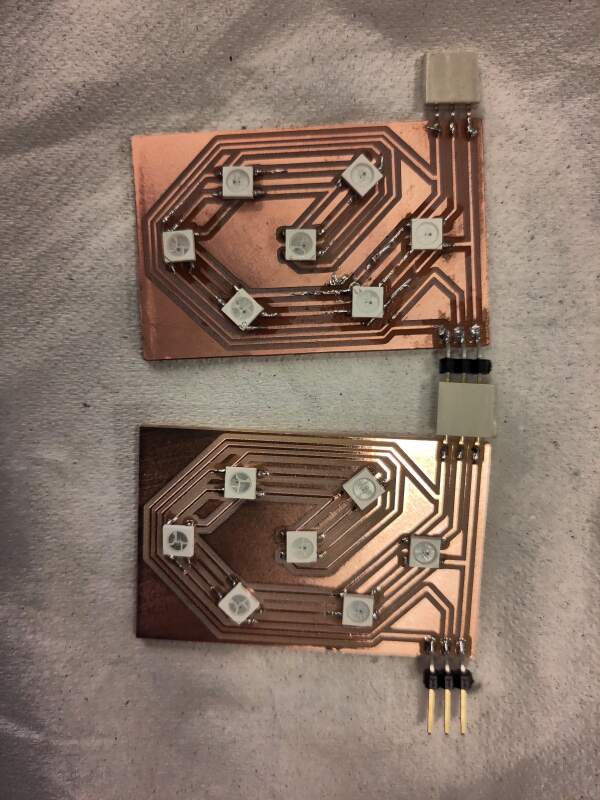
Less stunned, still stressed and hungry, but with regained drive, I started milling another board because the traces starting to come off the first PCB after all the soldering and desoldering. While that was running, I cleaned up the first PCB as best as I could and soldered the other 5 LEDs on.
Soldering ws2812b components was annoying because solder doesn't really want to stick to the pins. I used soldering flux (S-39) to pre-tin the pins before putting them on the board. That made it a lot easier to solder them down, but it was a bit harder to get them flush on the board. I had so much practice soldering this day that making a second board was a breeze.
Running the code from the earlier strand test.
Now let's make a two-digit counter!
import machine, neopixel, time

A=0
B=1
C=2
D=3
E=4
F=5
G=6

DIGITS=[[A, B, C, D, E, F],
        [B, C],
        [A, B, G, E, D],
        [A, B, G, C, D],
        [F, B, G, C],
        [A, F, G, C, D],
        [A, F, G, E, C, D],
        [A, B, C],
        [A, B, C, D, E, F, G],
        [A, F, B, G, C, D]]

C = (100, 100, 100)

def digit(np, arr, offset=0):
    for i in range(7):
        np[offset + i] = (0, 0, 0)
    for i in arr:
        np[offset + i] = C

n= 14
np = neopixel.NeoPixel(machine.Pin(0), n)

for i in range(100):
    digit(np, DIGITS[i // 10], 0)
    digit(np, DIGITS[i % 10], 7)
    np.write()
    time.sleep(.5)
It works!
3.2.2. Sound
At first, I wanted to try the audio PWM class D example in the output devices class notes, but I could not make sense of the schematics. I did find this article from Fablab Kannai, but it had a clear "WIP" label on it, and I have limited time to explore. I asked on Mattermost about the class notes, and Adrian Torres immediately provided the answer.
All these solutions seemed too complicated and time-consuming. So, I brought two piezo elements from the Waag to experiment with at home. I could not find any markings on the packaging to hunt for a datasheet, so I decided to just put a PWM wave on it to listen for sound.
import machine, time

PIN=0
pin=machine.Pin(PIN)
pwm=machine.PWM(pin)

pwm.freq(300)
pwm.duty_u16(65536//2)
time.sleep(1)

pwm.freq(200)
time.sleep(1)

# off
pwm.duty_u16(0)
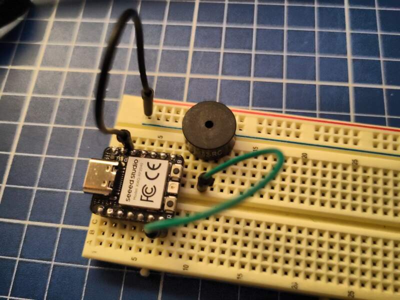
The result was underwhelming. One of the Waag elements produced no sound at all, and the other sounded like it was blown up. I found another at home in my "electrical stuff" bin which sounded better but not loud enough to function as an alarm sound.
Also, it's not nostalgic in a good way; it's just ugly, and there's plenty of ugly music to play on a piezo for those interested:
I did not bother to put all this on a PCB for this week. I will investigate the "DFR0299" MP3 for my final project later to get some better and more fun sounds in the alarm clock.
4. Reflection
I did not have a good week and found it hard to ask for help.
It took me some days to realize this week is about power. It did help me focus a bit more on my final project, so I investigated battery charging and found out the XIAO RF2350 has that build in.
4.2. Bad
My documentation is getting leaner and leaner. I am either slowly failing or finding the right balance? I did put in a lot of effort this week.
Also, I noticed a mistake in my digit design. I think it would be better to have it terminate in a female header instead of pins, because having live pins is asking for shorts.
5. Source Files
NeoPixel digit board
KiCad:
Code:
- neopixel-digit-test.py
- neopixel-pcb-tester.py (corrected script used for testing while soldering)
NeoPixel digit board (cut outs from strip, unused)
KiCad:
NeoPixel digits controller board (unused)
KiCad:
