Networking and Communications
1. Week Assignments
individual assignment:
- design, build, and connect wired or wireless node(s) with network or bus addresses and local input &/or output device(s)
group assignment:
- send a message between two projects
2. Prior Knowledge
I work with networked software for a living but have not done any hardware networking beyond plugging in network cables, setting up WiFi or connecting something over Bluetooth. Oh, and playing with a LoRa MeshCore board.
3. Work!
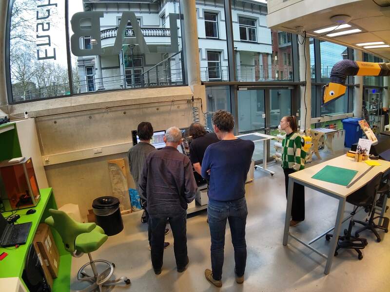
For this week's lecture, we visited the FabLab in Enschede. Our local instructor, Leo, works there and we wanted to see the lab.
3.1. Group Assignment
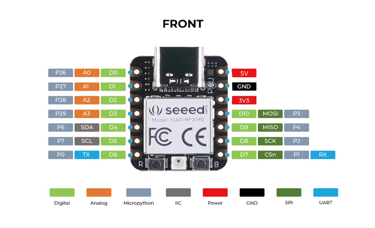
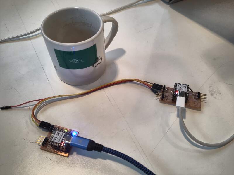
As a group, we connected two XIAO RP2040s over UART using boards we created in the previous weeks. Initially, we connected the two XIAOs using jumper wires, using the designated UART pins (TX and RX) as depicted in the pin overview from Seeed.
With this setup, we exchanged some banter using MicroPython and Arduino scripts, transmitting from one computer through the RP2040s to the other computer.
To connect "two projects", we reviewed the boards we created in the last few weeks for two suitable candidates. Using some of the pins at hand did not work until Heleen discovered that UART requires the use of UART peripherals, of which a RP2040 has two. This limits the pins which can be used together for UART communication. For more details about this, refer to section "4.2. UART" in the RP2040 datasheet and rp2/machine_uart.c in the MicroPython source code. Fortunately, the boards we selected provided enough pin combinations to select functioning sets of pins.
In the end, we devised a small protocol to control the LEDs on one boards on from the other. The board with the LEDs ran the following code:
from machine import UART, Pin

TX=Pin(0)
RX=Pin(1)

uart = UART(0, 9600, bits=8, parity=None, stop=1, timeout=1000)

led1 = Pin(26, Pin.OUT)
led2 = Pin(27, Pin.OUT)

while True:
    cmd = uart.readline()
    if cmd == b"l1on\n":
        led1.value(1)
    elif cmd == b"l1off\n":
        led1.value(0)
    elif cmd == b"l2on\n":
        led2.value(1)
    elif cmd == b"l2off\n":
        led2.value(0)
The other board ran:
#include <Arduino.h>

#define HELEEN_BAUDRATE 9600
#define PC_BAUDRATE 9600

long randNumber;

void setup() {
  Serial.begin(PC_BAUDRATE);
  Serial1.begin(HELEEN_BAUDRATE, SERIAL_8N1);

  while (!Serial) {
    ; // Wait till USB connection is available
  }

  Serial.println("Started");
}

void loop() {
  randNumber = random(10);
  Serial.println(randNumber);

  if (randNumber < 5) {
    Serial1.write("l1on\n");
    Serial1.write("l2off\n");
  }
  else {
    Serial1.write("l2on\n");
    Serial1.write("l1off\n");
  }

  delay(100);
}
This resulted in a nostalgic network flickering effect (video by Christian).
3.2. Individual
Struggling to find a good networking example to do for this week, I
came up with something ridiculous: networking over a WS2812B strip!
We can send data to the LEDs on a strip, but the last LED also has a
DOUT pin. What if we use a microcontroller to read from such pin to
get data?
From the datasheet:
| T0H | 0 code, high voltage time | 0.4us | ±150ns |
| T1H | 1 code, high voltage time | 0.8us | ±150ns |
| T0L | 0 code, low voltage time | 0.85us | ±150ns |
| T1L | 1 code, low voltage time | 0.45us | ±150ns |
| RES | low voltage time | Above 50µs |
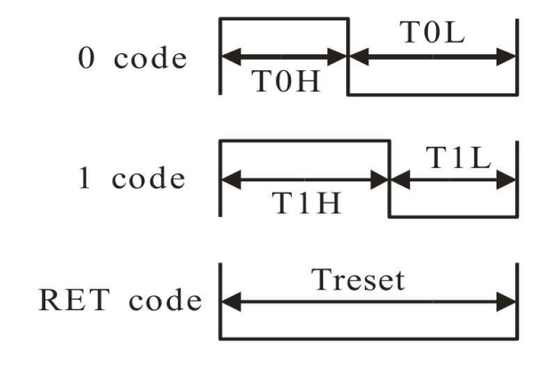
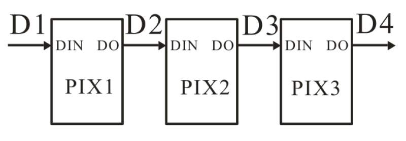
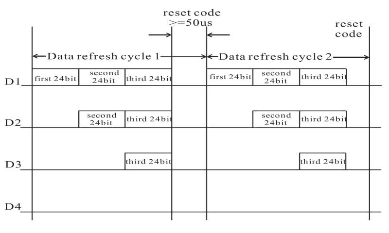
So, bits are sent by setting the data pin the high and then low. When
the duration of the high pulse is longer than the low pulse, it's a 1;
otherwise it's a 0. The color values are 24 bits long (encoded as GRB
instead of the RGB). Each time an LED receives a burst of bits on the
DIN pin, it takes the first 24 bits and sends the remaining bits to
its DOUT pin. When the pin goes low and stays low, the LED is set
to the received color.
I wanted to try receiving data from the DOUT of the last pixel.
At first, I tried reading the data by using an IRQ handler on a GPIO
pin of a receiving RP2040. I set up a another RP2040 to send data
using the NeoPixel library, by connecting their GND pins and GPIO 0
pins. Below is the code I ran on the receiver:
from machine import Pin
from time import sleep, ticks_us
import _thread

last_high = 0
last_low = 0
highs = []
lows = []
lock = _thread.allocate_lock()

results = []
def irq_handler(pin):
    global last_high, last_low, highs, lows
    now = ticks_us()

    lock.acquire()
    if pin.value() == 1:
        lows.append(now - last_high)
        last_high = now
    else:
        highs.append(now - last_low)
        last_low = now
    lock.release()

pin = Pin(0, Pin.IN, Pin.PULL_UP)
pin.irq(trigger = Pin.IRQ_RISING | Pin.IRQ_FALLING, handler = irq_handler)

while True:
    print(highs, lows)
    sleep(0.5)
Sending NeoPixel data resulted in a lot of useless data because the
ticks_us resolution was too low, and appending to an array in
MicroPython takes too long.
This was clearly a task for PIO programming. Taking inspiration from:
- github.com/jetsonhacks/pico-read-pwm/pio/pio_simple_single.py
- github.com/micropython/micropython/examples/rp2/pio_uart_rx.py
I set out to roll some PIO code to read from the bit fire hose. After hours of trail and error (this is my first time programming PIO), I came up with the following:
from machine import Pin
import rp2
import time

PIO_RX_PIN = Pin(0, Pin.IN, Pin.PULL_UP)

@rp2.asm_pio(autopush=True,
             push_thresh=24,
             fifo_join=rp2.PIO.JOIN_RX,
             in_shiftdir=rp2.PIO.SHIFT_LEFT)
def b24in_asm():
    wrap_target()

# loop
    label("loop")
    wait(1, pin, 0)

    set(x, 15)

# high
    label("high")
    nop().delay(1)
    jmp(x_dec, "waiting")

    set(x, 1)
    in_(x, 1)
    jmp("next")

# waiting
    label("waiting")
    jmp(pin, "high")

# low
    set(x, 0)
    in_(x, 1)
    jmp("next")

# next
    label("next")
    wait(0, pin, 0)
    wrap()

sm = rp2.StateMachine(0,
                      b24in_asm,
                      freq=125_000_000,
                      in_base=PIO_RX_PIN,
                      jmp_pin=PIO_RX_PIN)
sm.active(1)

while True:
    v = sm.get() & 0b111111111111111111111111
    print(f"{v:024b}")
Programming PIO is quite straightforward but finding the correct values for the wait loop and choosing the best frequency took me some time.
I tested this with two RP2040s (XIAO and RP Pico) directly connected
using the code below. Note: I used bit patterns to allow for visual
inspection. At first, I forgot a wait(0, pin, 0) at the end of the
loop, which resulted in very unstable readings. After some tweaking
(especially the timing), it ran fine for a maximum of 10 colors (that
30 bytes of data!!) then end with 24 garbage bits. I think
MicroPython just can't keep up with the data coming in and the RX FIFO
gets overwritten, or the PIO program stalls.
import machine, neopixel
np = neopixel.NeoPixel(machine.Pin(0), 3)
np[0] = (0b10101010, 0b11111111, 0b10101010) # RGB -> GRB
np[1] = (0b00000000, 0b10101010, 0b11111111)
np[2] = (0b11111111, 0b00000000, 0b01010101)
np.write()
Now it was time to place some LEDs between them. I used the digits I created in week 10.
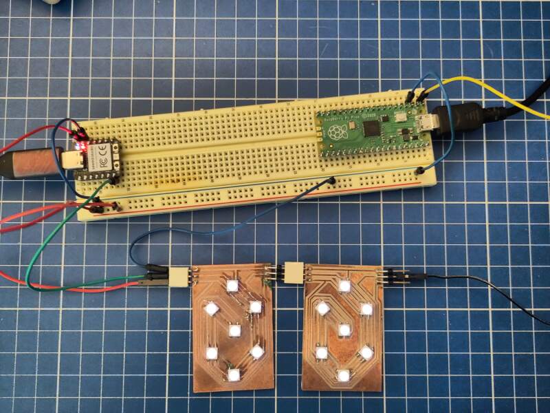
I ran the script below to light up the digits and send some additional bit patterns to Raspberry Pi Pico.
import machine, neopixel
n = 16
np = neopixel.NeoPixel(machine.Pin(0), n)

# light up the digits
for i in range(14):
    np[i] = (1, 1, 1)

# additional bit patterns
for i in range(14, n):
    np[i] = (0b00001111, 0b10101010, 0b11110000)
np.write()
Here's the result:
$ mpremote a1 run content/11-networking/read-pin-pio.py
101010100000111111110000
101010100000111111110000
Notice how the RGB code 000011111010101011110000 morphed into the
GRB code 101010100000111111110000.
Now, let's send a secret message!
import machine, neopixel

msg = "fab academy!"
msg_len = len(msg) // 3

n = 14 + msg_len
np = neopixel.NeoPixel(machine.Pin(0), n)
for i in range(14):
    np[i] = (1, 1, 1)

# encode the message into colors
for i in range(0, msg_len):
    np[i + 14] = (ord(msg[i * 3]), ord(msg[i * 3 + 1]), ord(msg[i * 3 + 2]))
np.write()
I modified the loop on the receiving end to decode the message as follows:
while True:
    v = sm.get()
    m = chr((v >> 8) & 255) + chr((v >> 16) & 255) + chr(v & 255)
    print(m, end='')
$ mpremote a1 run content/11-networking/ws2812b-receive-secret-message.py
fab academy!
It worked!
To make it a bit prettier, I added two PCBs: one for the sender and one for the receiver. To the latter, I added an OLED screen to display the secret message.
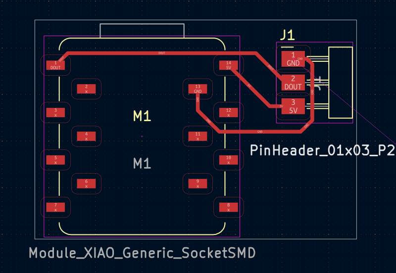
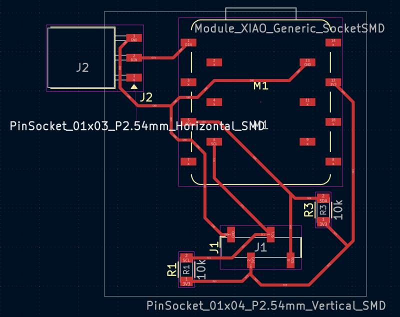
For the receiving end, I made the following adjustments.
from ssd1306 import SSD1306_I2C
from machine import I2C
from time import sleep

i2c = I2C(1, scl=Pin(7), sda=Pin(6), freq=200000)
oled = SSD1306_I2C(128, 64, i2c)

oled.fill(0)
oled.text("ready", 0, 0)
oled.show()
sleep(2)

while True:
    m = ""
    while sm.rx_fifo() > 0:
        v = sm.get()
        m += chr((v >> 8) & 255) + chr((v >> 16) & 255) + chr(v & 255)

    if len(m) > 0:
        oled.fill(0)
        oled.text(m, 0, 0)
        oled.show()
And some playful changes on the sending side.
import machine, neopixel, time

msg = "fab academy!"
msg_len = len(msg) // 3

n_leds = 7
n = n_leds + msg_len
np = neopixel.NeoPixel(machine.Pin(26), n)

for i in range(n_leds):
    np[i] = (32, 0, 0)
    np.write()
    time.sleep(0.5)

for i in range(0, msg_len):
    np[i + n_leds] = (ord(msg[i * 3]),
                      ord(msg[i * 3 + 1]),
                      ord(msg[i * 3 + 2]))
np.write()
Et voilà! Secret messages over a network of NeoPixels!
Did it work? Yes! Is it stable enough? No, sometimes the PIO program enters a bad state and extra bits are inserted or bits are dropped. This is regardless of the amount of data, and my also be due to noise on the line. There are likely things I can do about this, but this is fine as a proof of concept.
4. Reflection
It was a pretty good week. My documentation isn't as extensive as it was in the earlier weeks, but I think I've just trimmed of some unnecessary details, and expect it is sufficient.
I was a bit lost this week because I didn't think networking was that interesting. However, it did give me some room to challenge myself and try something silly. I feel fortunate that it actually works, as I could have failed horribly this week.
4.2. Bad
I made some mistakes while milling boards. At first, I was unable to get the mill to remove enough copper to create traces. Then, the mill went too deep, fraying the sides of the traces. Henk helped, and we hypothesized that mill bit was blunt. Replacing it resulted in a perfect milling job, so I learned a lot from this experience. Should I move this part to 4.1 section?
4.3. Ugly
I keep feeling like I have to do everything as fast as possible, especially when I am working in the lab. This results in stupid mistakes, such as swapping ground and power on a board I created this week and not looking at my code like last last week.
