- Assignments
- Shopbot instructions
- Group assignment
- VCarve notes
- Design
- VCarve Pro
- CNC
- Reflection
- Things that went wrong
- Files
- CNC theory notes
Computer-Controlled Machining
Make something big! I’ve used the Shopbot a couple of times before and have given instructions on it. For this week I wanted to make something useful (for a change). If it has to be big and in my house, it needs to be something that I can store stuff in. My goal for this week is to learn more about how to finish a piece of furniture nicely and to put in a lot of effort into one thing. I tend to go for quantity over quality because I love to experiment and before I finish one thing I’m already working on the next. This week I want to do it differently and look at how machines and manual craft meet each other.
Assignments
| Progress | Task |
|---|---|
| Done | Complete your lab’s safety training |
| Done | Group assignment: test runout, alignment, fixturing, speeds, feeds, materials and toolpaths for your machine |
| Done | Document the group assignment |
| Done | Make (design+mill+assemble) something big |
| Done | Documented how you designed your object (something big) |
| Done | Documented how you made your CAM-toolpath |
| Done | Documented how you made something BIG (setting up the machine, using fixings, testing joints, adjusting feeds and speeds, depth of cut etc.) |
| Done | Described problems and how you fixed them |
| Done | Included your design files and ‘hero shot’ of your final product |
Shopbot instructions
On Thursday we started with the safety training and and an introduction into how to operate the Shopbot by Saco. I’ve documented the Shopbot steps 3 years ago already during my internship at the fablab, so the following documentation is a revisited and updated version of my documentation here.
Safety
- First of all: NEVER leave the machine while it is running
- Wear long hair in a bun so you cannot get your hair in a spinning spindle. People have died because of this so don’t risk it
- Wear safety glasses
- There are two ways to get out of the CNC room safely: through the fablab and through the emergency exit in the tower in the opposite corner of the CNC.
- There are two foam extinguishers in the CNC room; however if the dust bag is starting to burn you should throw it out of the window
- A spindle spinning at 18000 rotations per minute is DANGEROUS. Be extremely cautious with the placement of the bolts in the material because when you bump into metal with the mill it will generate sparks. In combination with sawdust there is the risk of fire or even explosion. Check everything you are doing constantly. A safety measure is to add the places for the bolt in the file and run those toolpaths first; this is the default way of working.
- If you do run into a screw: turn the machine off immediately with the emergency button and stop the ventilation, then take off the dust bag to check if there is a fire starting
Material preparation
Before turning on the machine you have to prepare your material. Clean the bed and sand if necessary (otherwise it may not be level, the screws from the previous milling job can leave litte bumps). Place the material: when using wood, you should first run a drilling toolpath for screw placement. When using foam, add double sided tape to the bottom of the material and stick it to the bed. Use two boards of wood to create a perpendicular angle, place the foam and use two more boards to surround the foam. This is because when it’s just taped the foam may come loose, ruining the whole model.
Spindle preparation
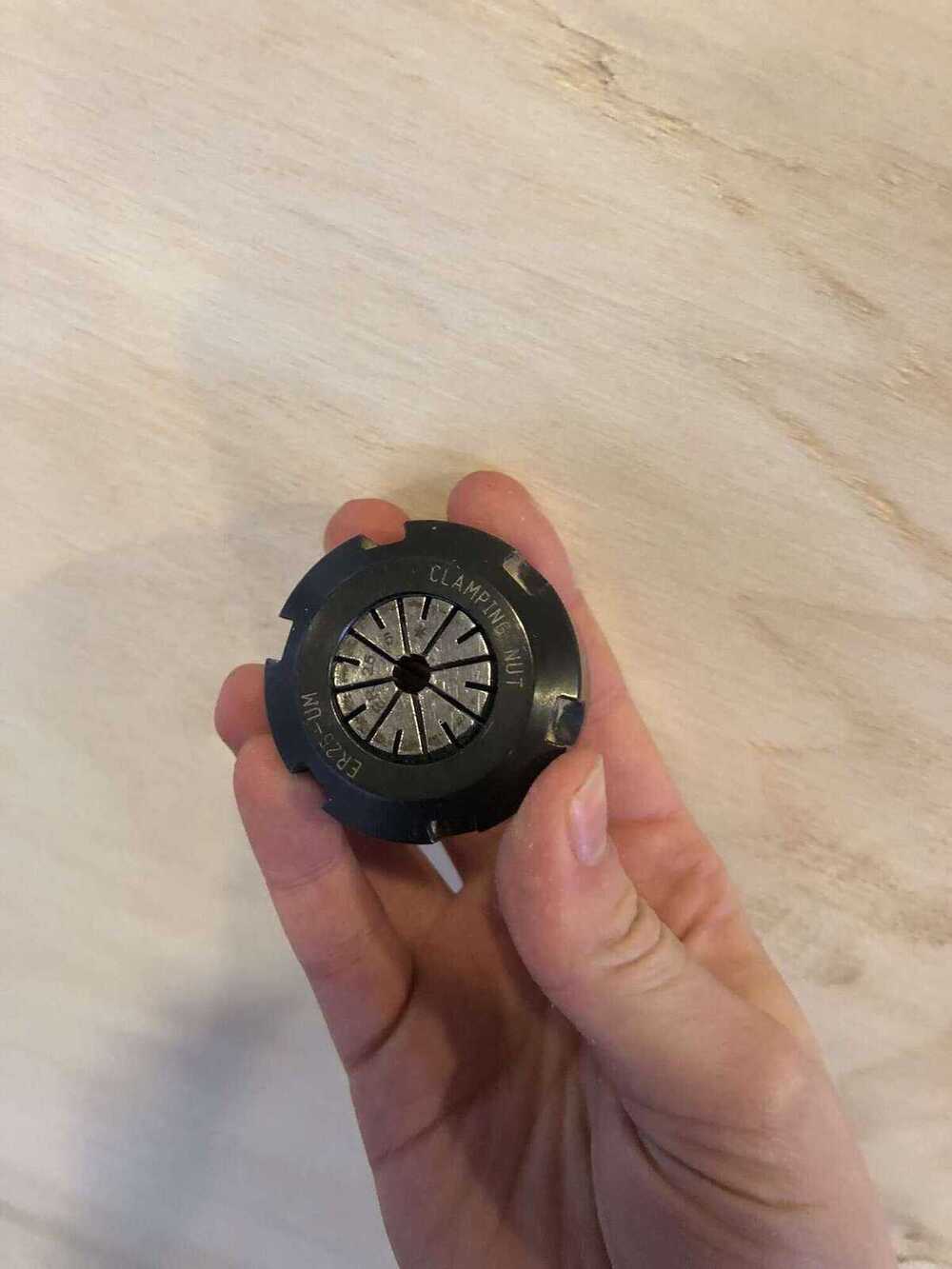
Grab the collet, nut and milling bit. Every diameter of milling bits has a matching collet that can be found in this case:

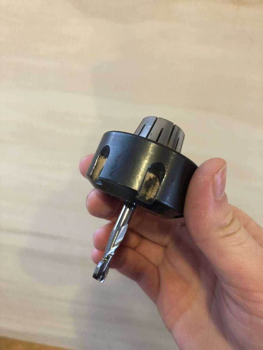
First put the collet in the clamping nut (you have to feel a click), then the milling bit in the collet. The milling bit should be put in until it is flush with the inside of the collet, like in the middle picture. If it sticks out too far, the collet cannot hold on enough to the bit, but if it’s too deep in the collet it’s also not good because the bottom part of the milling bits are hardened. This means that the collet cannot hold on as well, because the metal is less giving. Make sure the milling bit is sticking out far enough for your milling job.

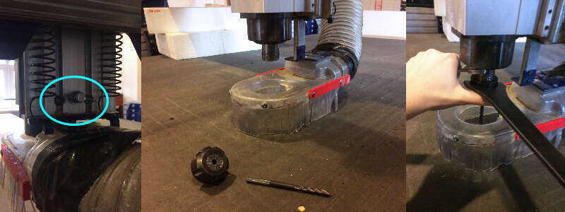
Lower the skirt by loosening the butterfly nut at the back of the machine head. Attach the collet/nut/bit assembly; it should be easy to do this manually, if it’s not then the nut is likely not attached right. Then tighten using the wrench and plier and put the skirt back.
Zeroing
Turn on the machine before opening the Shopbot software (otherwise there is no connection). After entering the keypad by pressing K in the Command bar, you can move the mill with the arrows in the keypad or the left arrow, right arrow, pgDown and pgUp.
Don’t start typing randomly when you are in the Shopbot Console because you may accidentally send all kinds of commands to the machine.
X & Y
First you have to zero the X and Y axes. Start with zeroing the machine with the Zero X/Y button so the machine looks for it’s absolute 0,0 point. Note that it’s not Jog home, which is the 0,0 button next to the Zero X/Y button. That one will make the machine go to the last home position.

Then move the machine to the preferred spot and take a screenshot or photo of the X and Y position displayed in the red Position window. Then go to Zero > Zero X and Y, or press 2. Now the current position is the new 0,0 or job home and the current X,Y position indicates 0,0. If for some reason the machine has to stop or the software crashes while milling, you can still continue with your file after zeroing it again with the saved position. This is where I started my milling job relative to the absolute home:

Z
Before zeroing the Z axis, test if the milling bit and metal tool connect. If they do, the light under output 1 in the Position window lights up green. Move the machine to the place where you’re going to zero. This should be somewhere on the sacrificial layer if you’re putting the Z zero on the bottom of the material (this is the standard). If you have a good reason to level on the top of the material that is also possible, as long as it matches what you defined as the Z zero in the Material Setup in Vcarve.
Put the metal tool under the mill and press the Zero Z button. The machine will stop moving down as soon as it touches the metal. The tool is 3.070mm thick so that is where it will stop. After that it moves up and down a little again to confirm the zero position, then move up a couple of millimeters and tell you whether the Z leveling succeeded.

If it went well, you will see this message:

Now put the metal plate back into its place; don’t remove the alligator clip like is suggested in the pop-up.
Starting a job
Load the Shopbot partfile exported from VCarve (don’t change anything in the summary) with the yellow folder button in the top left corner. Make sure you pick the correct file! VCarve files can have general names; if you pick the right name in the wrong folder you can imagine what can happen.
Turn on the power of the dust collector (switch in the back of the room, lamp turns green when it’s on), press the red button on the front of the machine (above the emergency button) to turn on the dust collector and use the knob to increase or decrease the power.

Then turn on the spindle by turning the key in the keyhole. The key to turn on the spindle is connected to the special wrench to release the nut from the spindle. This is so you can’t accidentally try to change milling bits while the machine is running.

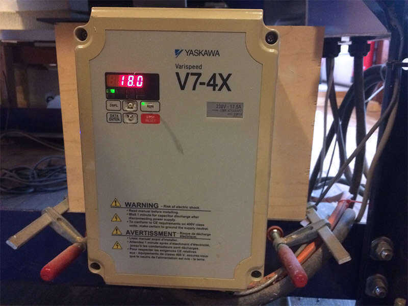
The spindle speed can be adjusted with the buttons on the box below the machine.
Keep your hand on the space bar for the first few minutes of milling to check if everything is going well; pressing the space bar pauses the machine, but it doesn’t stop the spindle from spinning. Make sure that you don’t leave the spindle spinning in one place because you can start a fire. When I’m milling something, I usually keep my hand on the space bar every time the machine moves to a next part to mill.
Troubleshooting
Parameter Error
I ran into this error when I changed the Move Speed for X and Y in the menu on the left side. I thought I had put in 90mm/s, but I think I didn’t do it right and it turned into 0.9mm/s instead. Then when I tried to move it didn’t move (or it moved really slowly, but I couldn’t see any motion). I fixed it by setting the speed to 90 again, but this time doing it right.

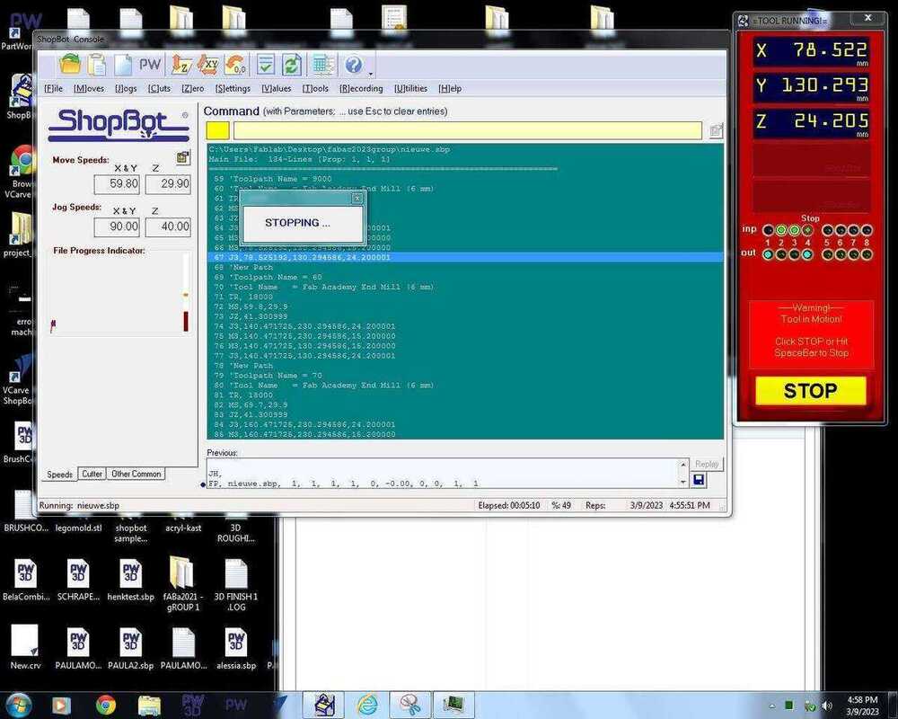
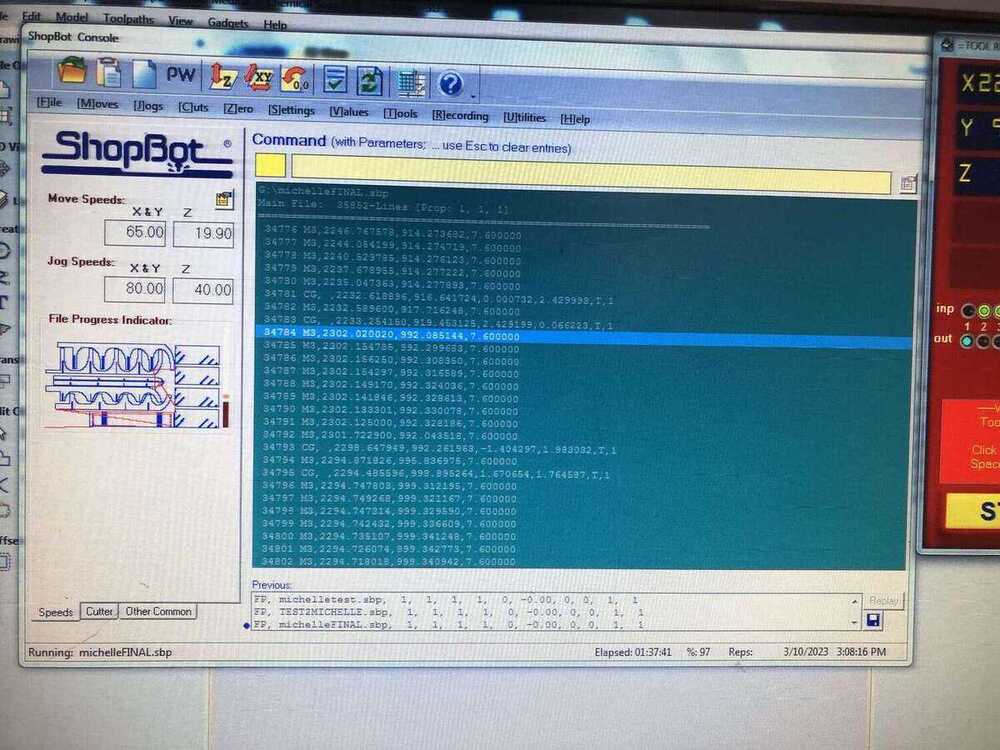
Shopbot freezing
While doing the group assignment, the Shopbot software stopped responding and got stuck on this screen when we pressed the space bar to pause the machine in between toolpaths to change the spindle speed. The Shopbot did pause. We tried restarting the software but that wasn’t enough (the Shopbot moved a tiny bit then stopped again), so we restarted the entire computer and the machine and started over with our file which went without hiccups. Luckily we took a picture of our X,Y home location.
Group assignment
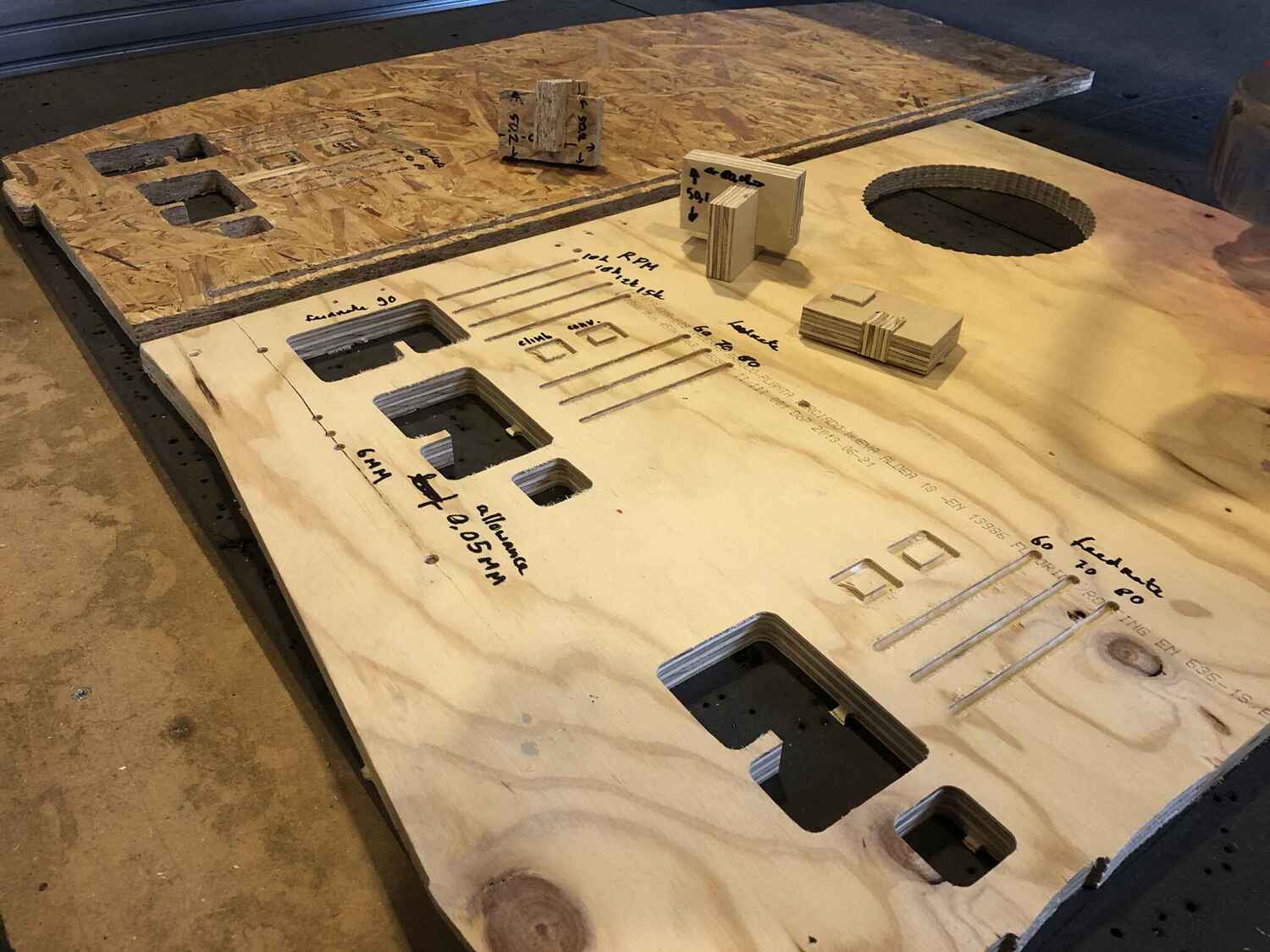
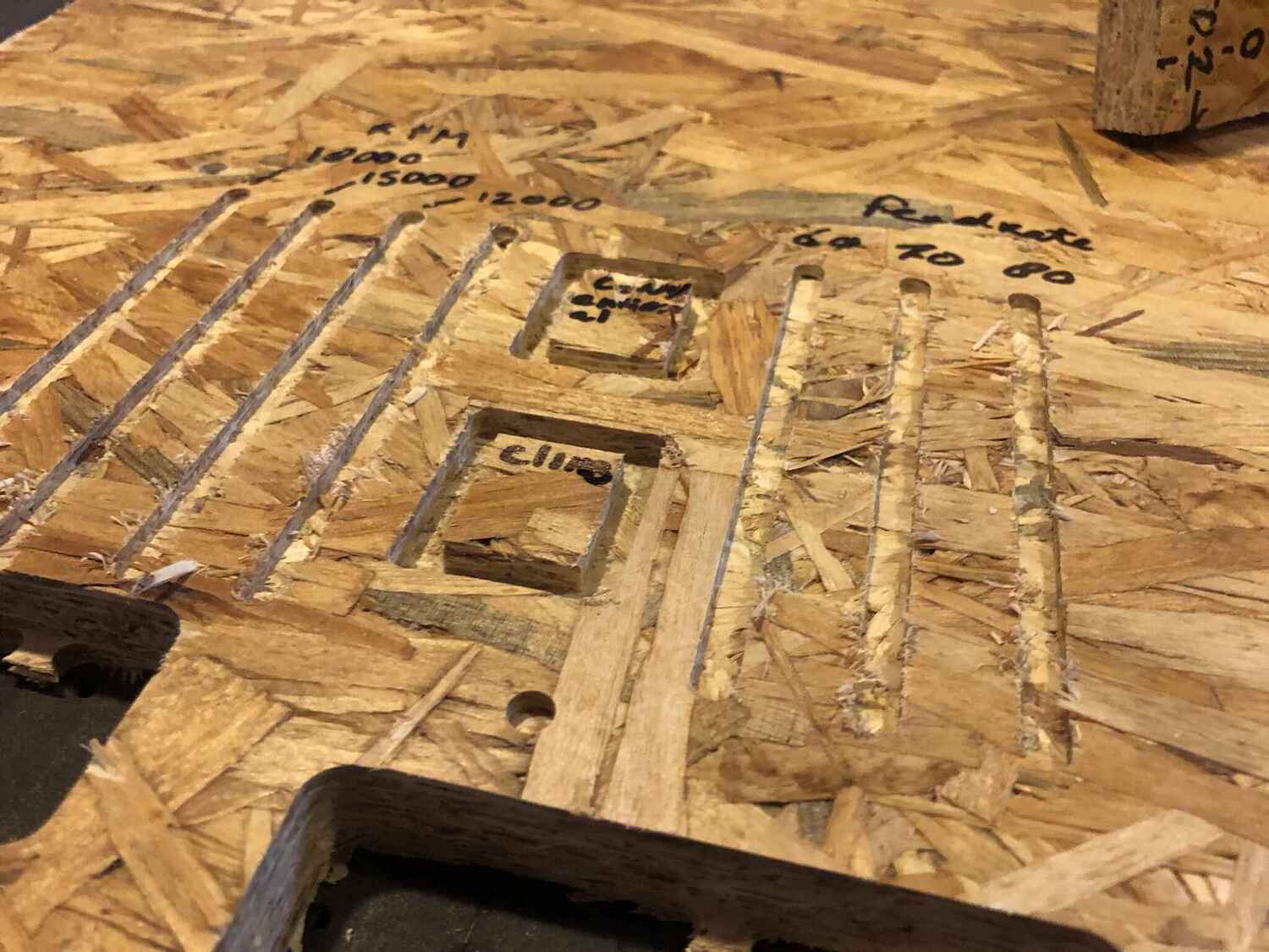
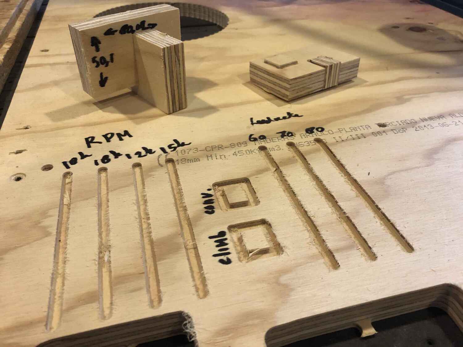
We made a small file directly in VCarve to test out feed rates, spindle speeds, runout and alignment, to try on plywood and OSB. Our observations are in the table below.
| Parameters | Findings |
|---|---|
| Thickness material OSB | 17,8mm |
| Thickness material plywood | 18,2mm |
| Drilling bit | 6mm |
| Speed | started with 90 mm/s but decreased to 60mm/s because the sound was terrible; very high pitched |
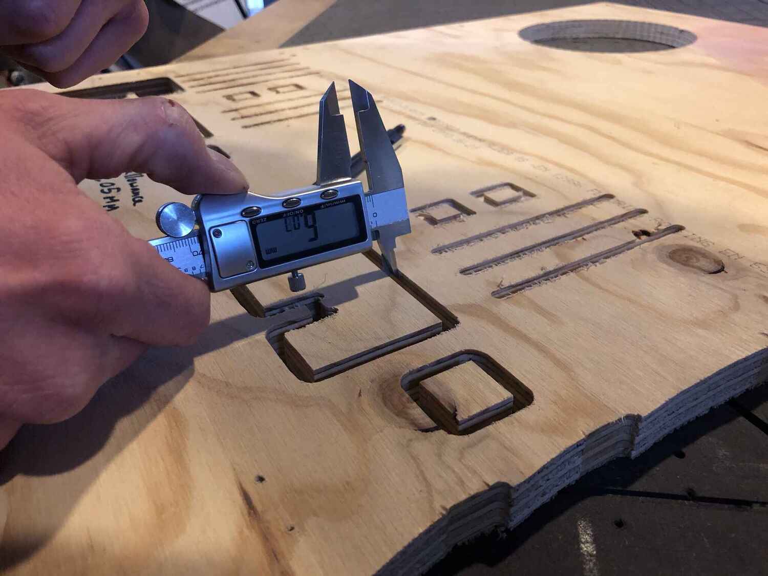
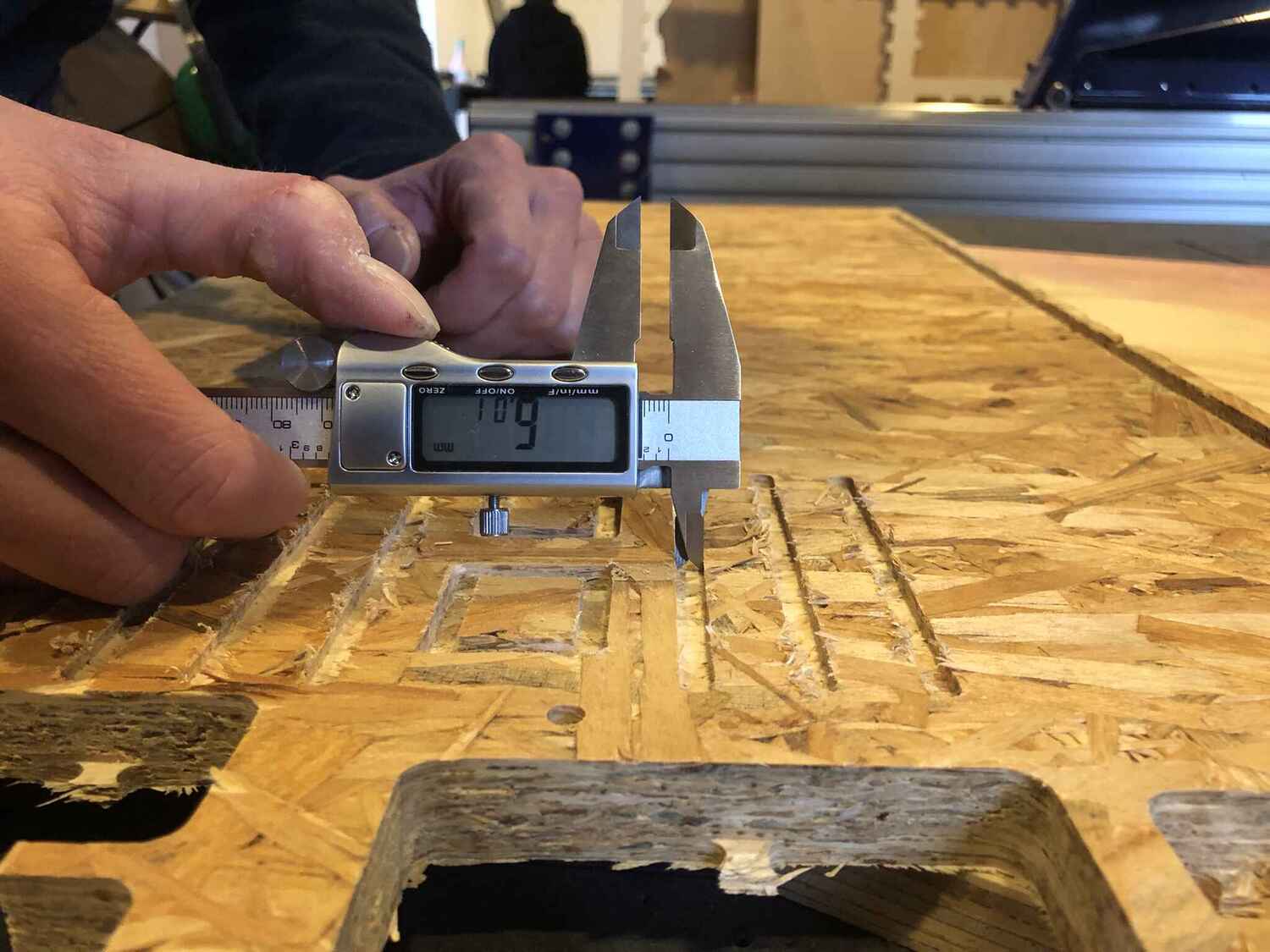
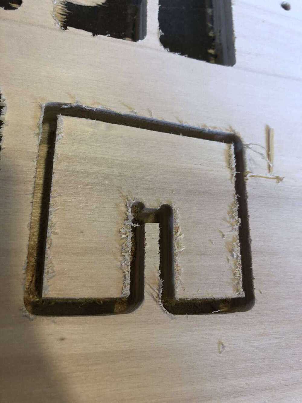
| Runout: the wobble of the milling bit (the tendency to spin the tool around a centerpoint that is not the tool’s center) | measured in various spots with 6,05mm as the highest number measured with a 6mm milling bit, not a very significant deviation, for OSB and plywood it is pretty much the same; OSB is slightly more irregular. Along the grain of of plywood the path is way nicer, so that’s where we measured |
| Alignment: calculate if angle is 90 degrees | let’s say it’s 1 degree for now, see picture |
| Fixturing: how you’re attaching materials to the sacrificial layer | using a drilling toolpath before milling anything else, we determine the placement of the screws, so there is no risk of accidentally placing a screw too close to the toolpaths |
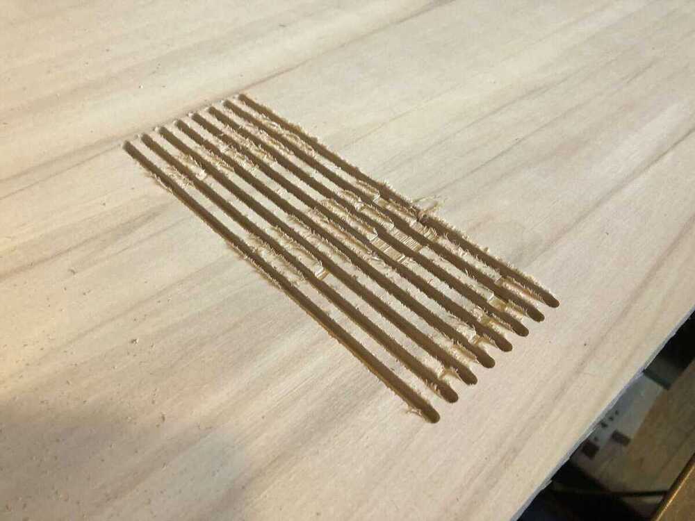
| Speeds: multiple lines with different speeds | we started with 90mm/s but that was too fast, it didn’t sound good (see video), 60 mm/s is a good base speed for plywood and OSB, higher speeds sound like the machine doesn’t love it. A feed rate of 60mm/s looks way nicer than 70, 80 or 90mm/s as you can see below. |
| Feeds: multiple lines with different feed but same speed | 18000 sounded pretty good, 15000 sounded worse and 12000 sounded like a struggle. On both materials a feedrate of 18000 looked best, 15000 and 12000 gave us messy lines |
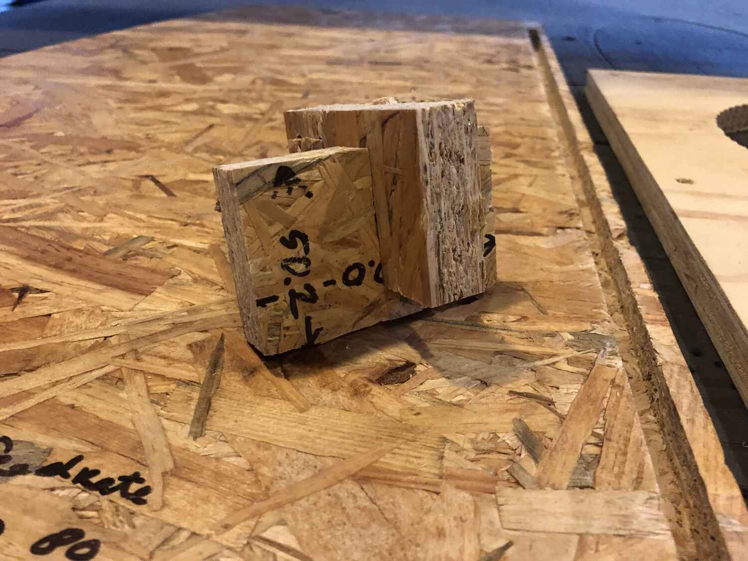
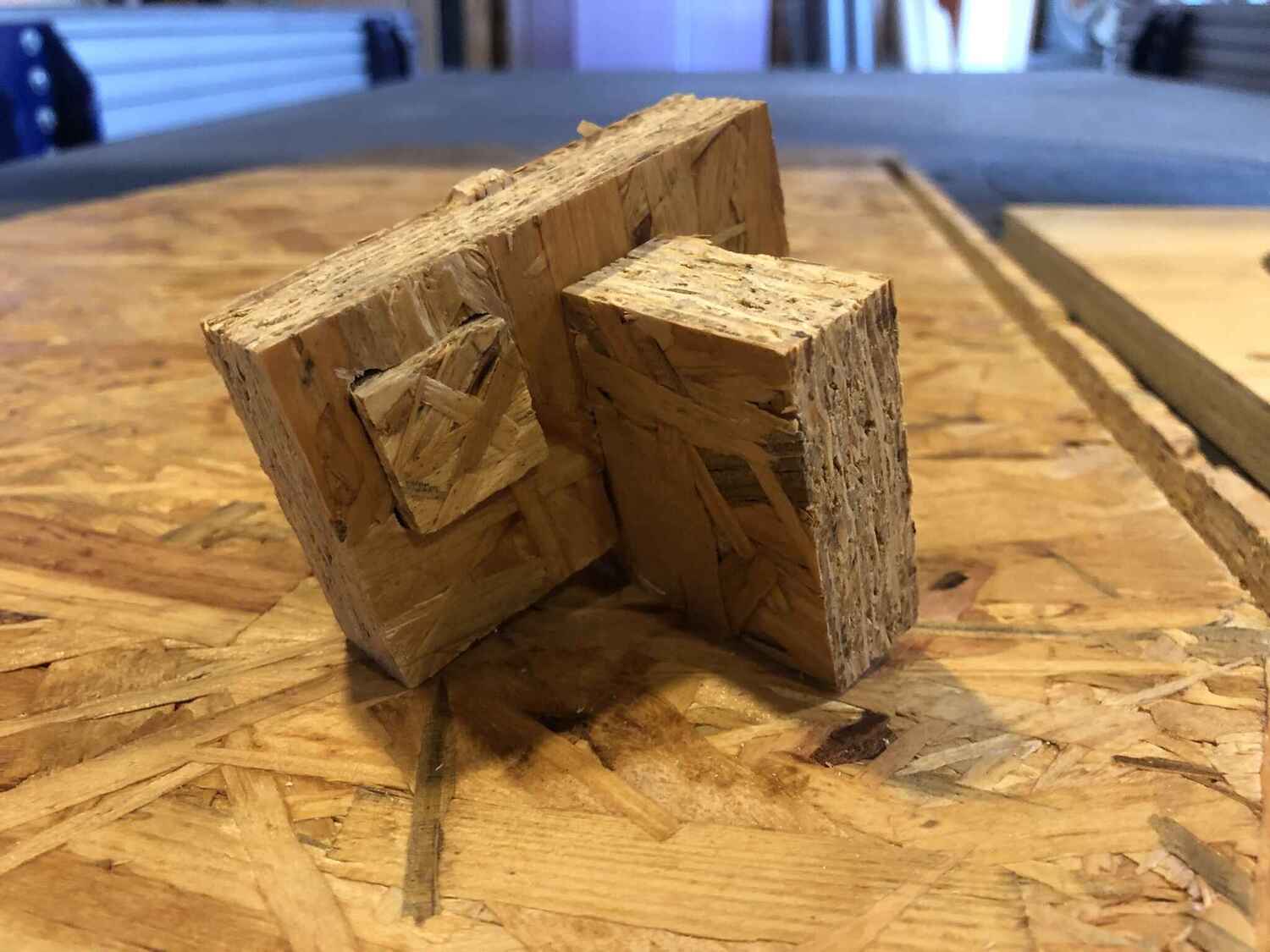
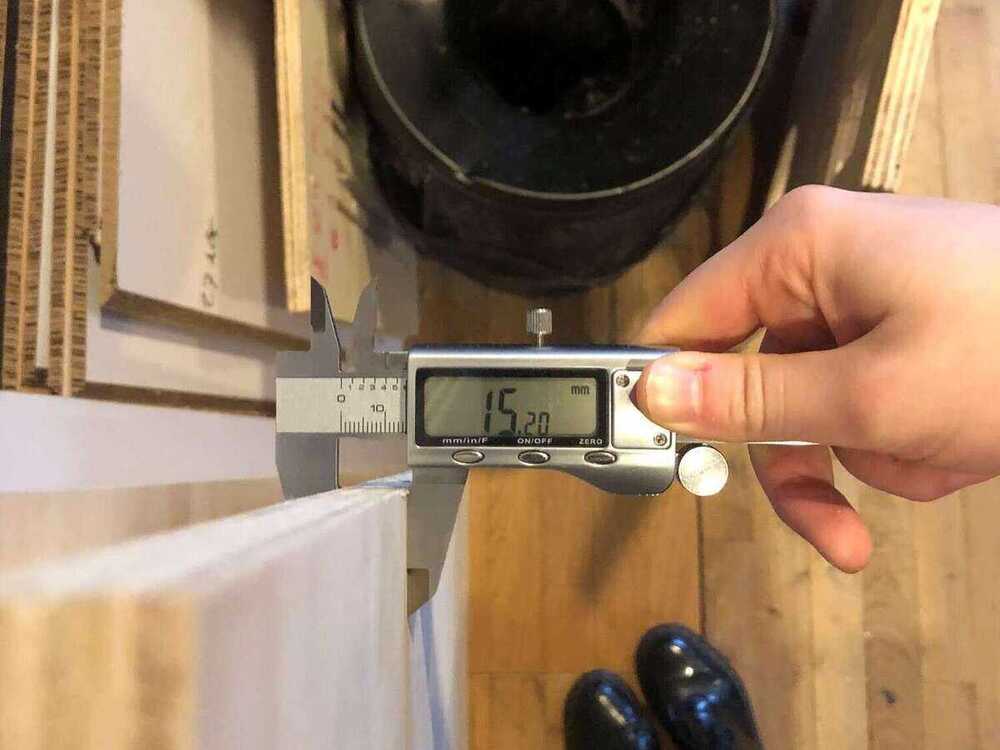
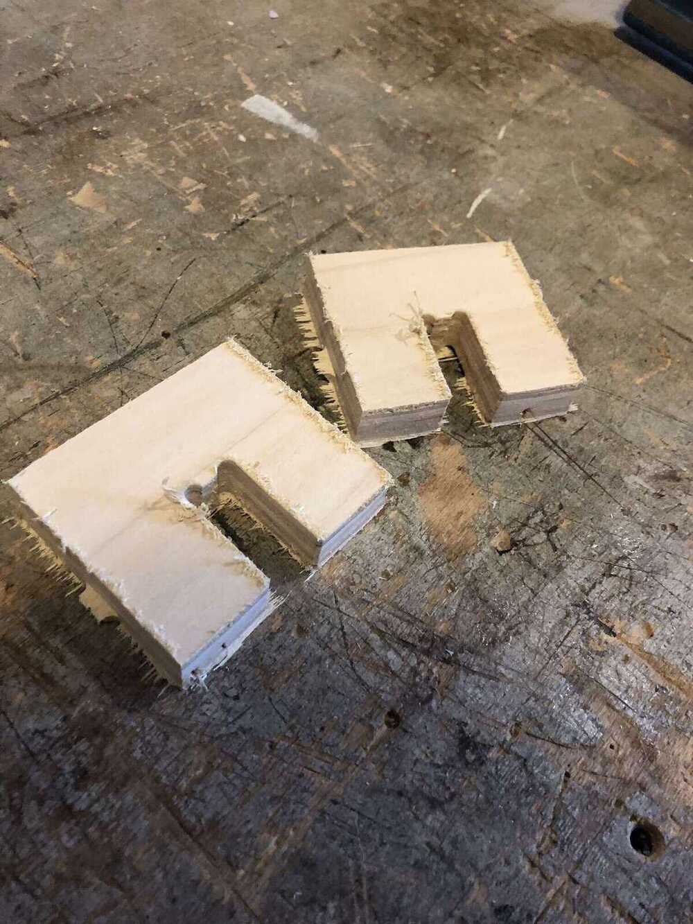
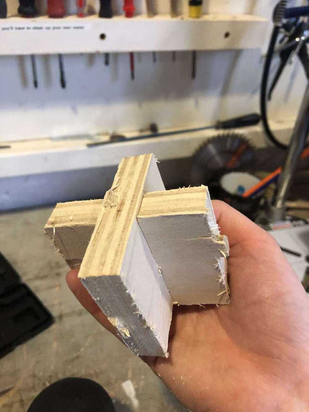
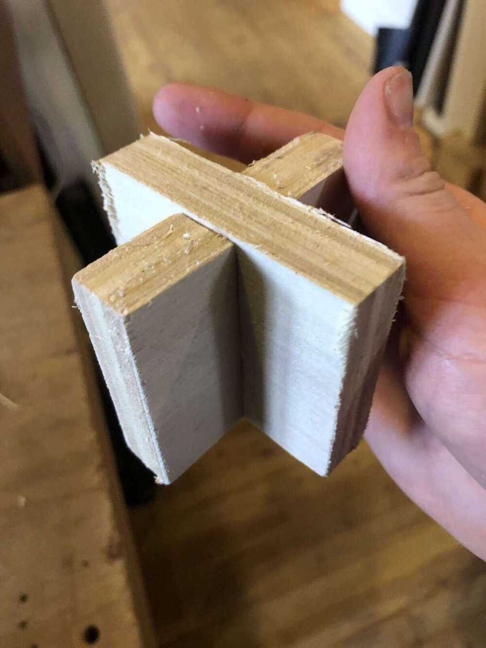
| Pressfit | Without any allowances, we got a very good pressfit for plywood with a diameter of 18,2mm. This same diameter worked well for OSB too, but it was a little less tight because we forgot to change the settings |
| Other observations | the plywood sounded terrible (very high pitch), might be the wood that is dry; no significant changes when using different speed and feed rate. OSB sounded much better |
Runout:
Alignment:

Feeds & speeds:
Press-fit & dimensions (plywood see picture above):
VCarve notes
Some general notes:
- Leveling on the sacrificial layer
- Drilling toolpath: make sure that the head of the screw is under the material to be safe
- Safe Z is 6mm above thickness of material
- Shopbot can ease in and ease out now; this is set up in the Shopbot software, not in VCarve
- VCarve Pro is the newer version of Partworks (2D and 3D)
- Design with Fusion360 (3d modeling software), Illustrator, Inkscape, Rhinoceros etc.
- Export designed file(s) as eps, ai, stl, pdf, dxf
- Always measure the thickness of your material at different places before you start designing
- You can also draw directly on the canvas
- You can set the order of cutting manually with vector selection order for all toolpaths
- Every time you change something, you need to recalculate the toolpaths!
Settings
- Tool type: end mill (flat) or ball nose mill (rounded)
- Diameter: diameter of the flute
- Pass depth: maximum depth of the material removed per pass (‘round’).
- Stepover: the distance between each pass of the machines tool head. The larger the stepover the faster the job will be machined, but the rougher the surface finish will be
- Spindle speed: rotations per minute of the mill. Maximum (and standard) is 18000 RPM. Changing this value here is only for your own information; you have to set this manually on the machine
- Feed rate: speed of traveling through the material
- Plunge rate: speed of traveling down into the material
| Multiplex | 6mm End mill | Rules of thumb |
|---|---|---|
| Pass Depth | 3mm | Depth per layer, half of the diameter to twice the diameter (but that’s a bit much). We use half of the diameter of the milling bit as a rule of thumb. You can customize pass depth per layer in VCarve |
| Stepover | Depends on finish | The higher the stepover, the smaller the overlap; stepover of 100% means no overlap; 0% is not possible for obvious reasons |
| Spindle speed | 18000 RPM | generally for wood this is set to the maximum our machine can handle, but Saco told us it would be better if we could go up to 100000 RPM |
| Feed Rate | 50/60 mm/s | RPM/100/amount of flutes. When using 2 flute end mills: for plywood keep 50/60mm/s in mind, for foam this can go up to 120mm/s |
| Plunge Rate | 20 to 30 mm/s |
Order
Keep this order of milling in mind:
- Drilling
- Pockets
- Inner cut-out
- Outer cut-out
Design
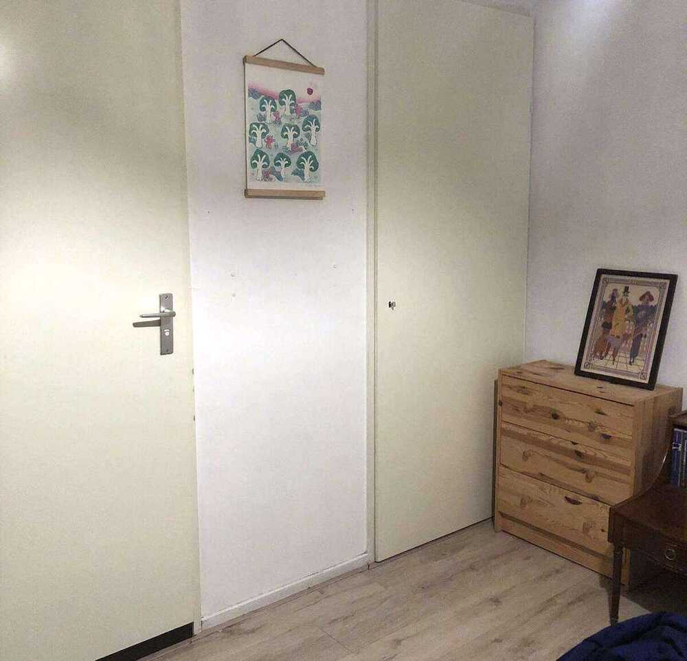
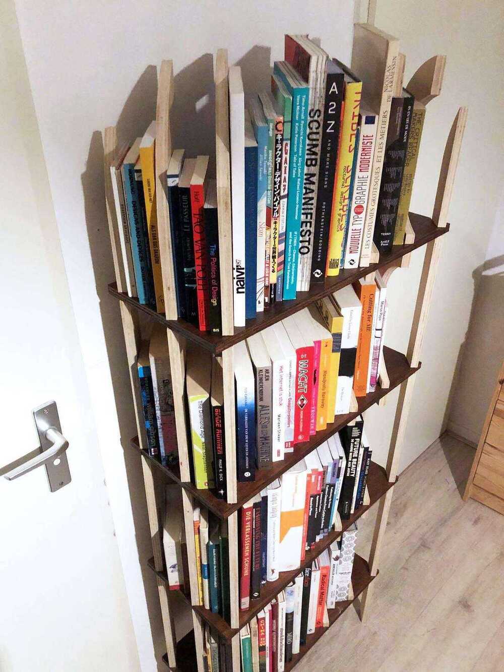
I have this corner in my bedroom that is in dire need of a nice cupboard. The wall between the two doors is 70cm wide, which apparently isn’t as common as I thought. I want a cupboard there that is not very deep (let’s say max 30cm), because any deeper looks weird there (I’ve made that mistake before) and I’m going to keep running into it otherwise.
This week was all about planning. I wanted to mill on Friday because on Thursday we would have class all day, on Monday I have to work and on Tuesday I wouldn’t have time to sand, paint, assemble and document everything anymore. This meant that I had to make my design on Wednesday night. I didn’t use Rhino this week, because of the time limit that I had and because I think Fusion is more suited for this kind of parametric design.
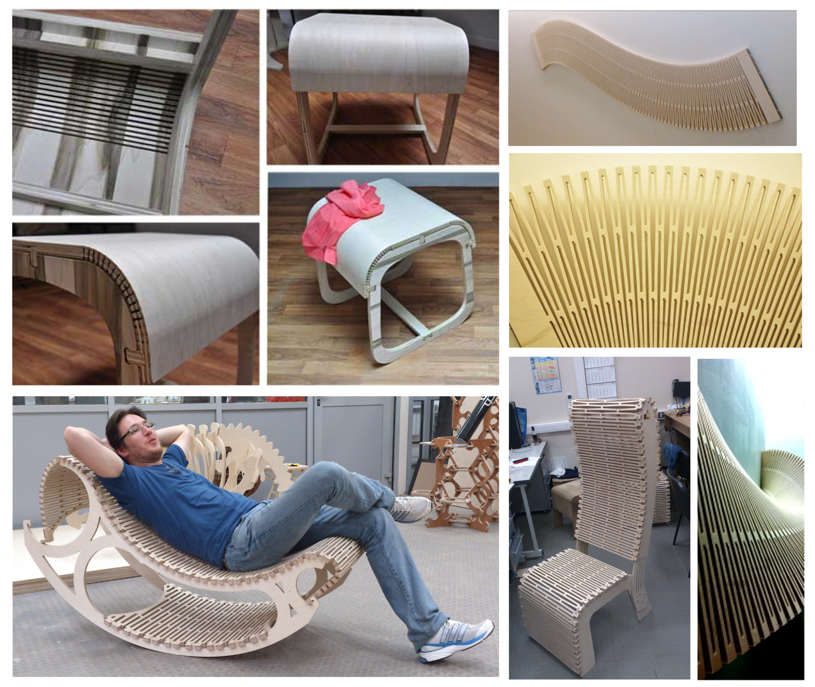
Wednesday morning I started by looking for some woodworking and CNC milling inspiration on Pinterest; the resulting board can be found here.
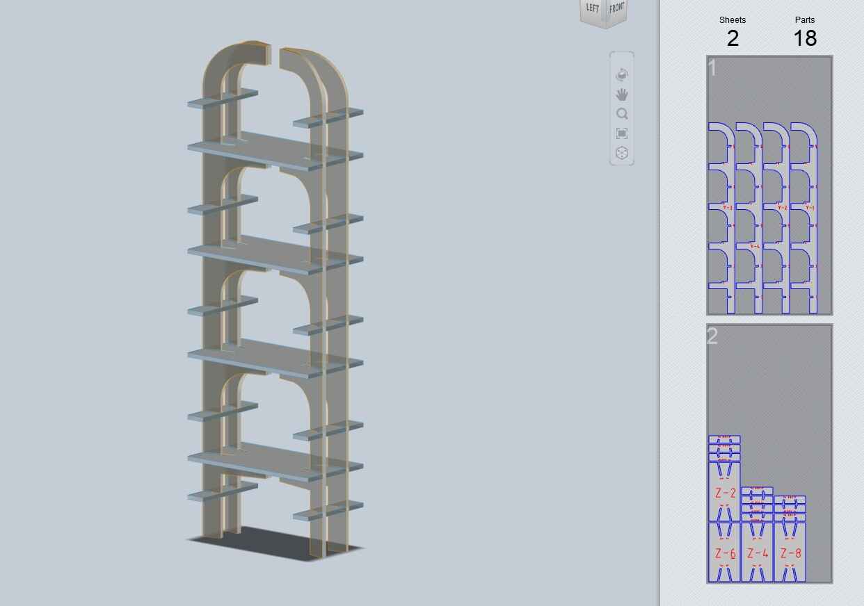
I started with the outline of a simple parametric bookcase in Fusion. My plan was to make a simple shape of a cupboard, then play with Slicer for Fusion360 to see if I could get an interesting piece of furniture. I didn’t really know what I wanted it to look like, so I wanted to play around with all kinds of slicing settings (co-designing with the computer!).
The height parameter is not used; the height is determined by the heightshelf and the thickness parameters.
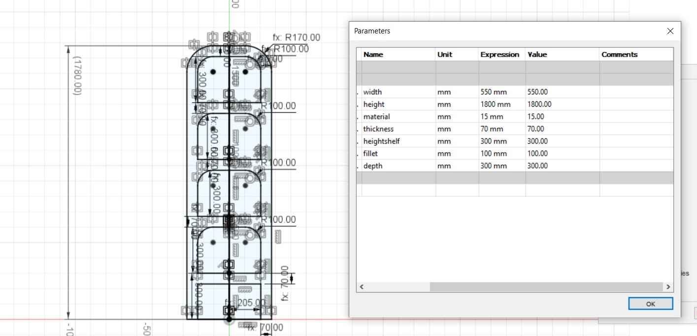
Then I extruded the sketch with the depth parameter.
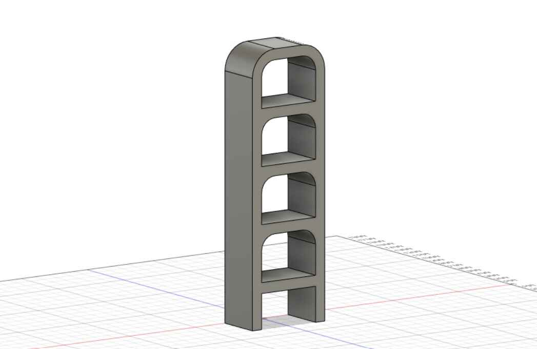
I then saved it as a mesh (STL) and imported the bookcase into Blender, because I wanted to try to make an organic looking piece of furniture.

I added a subdivision surface modifier and went to the Sculpt Mode.
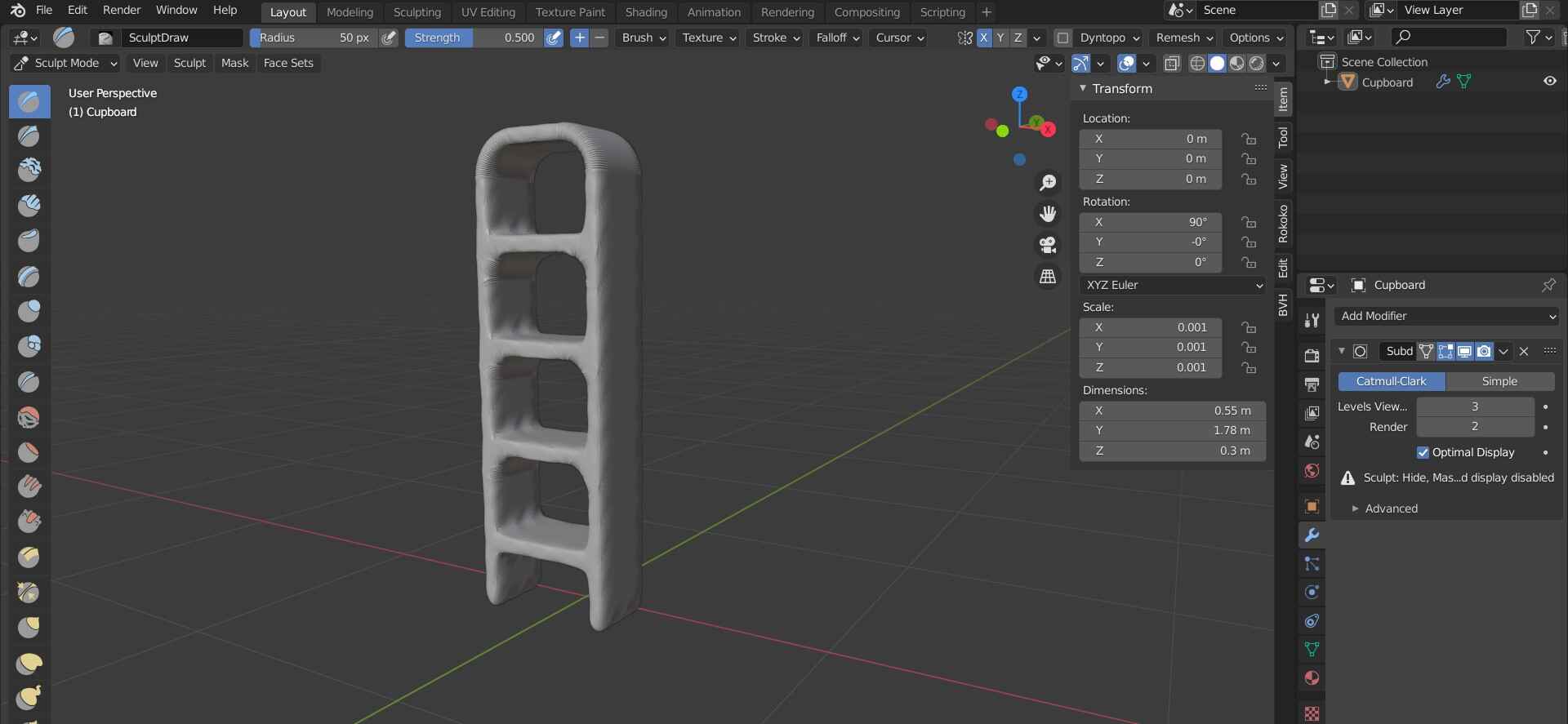
Here is a sped up video of me trying to scupt the bookcase. It works, but it’s just ugly.
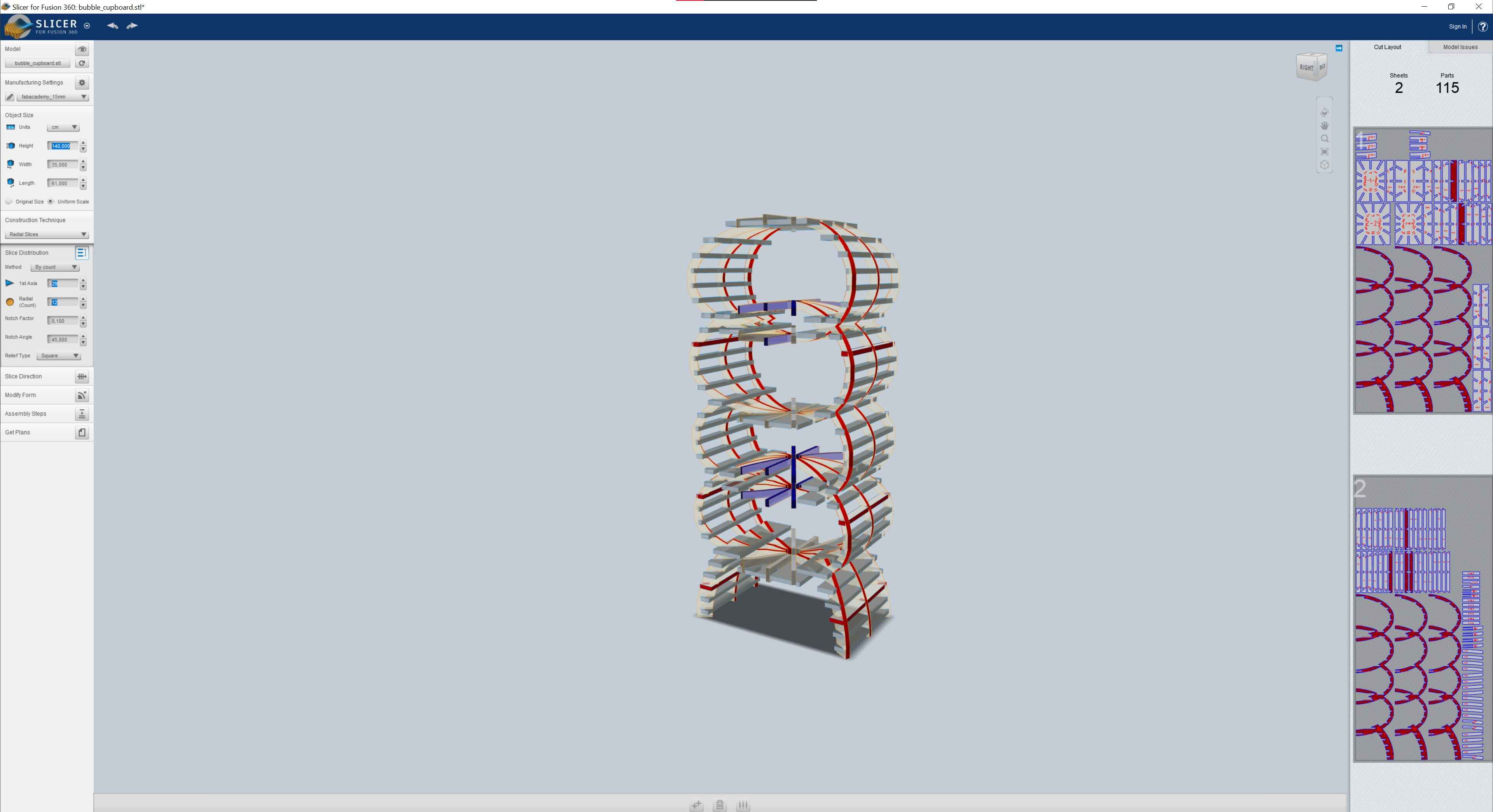
I still exported it as an STL and imported it into Slicer to see if it could turn it into an unexpected success. I set the Manufacturing Settings to the material I had.
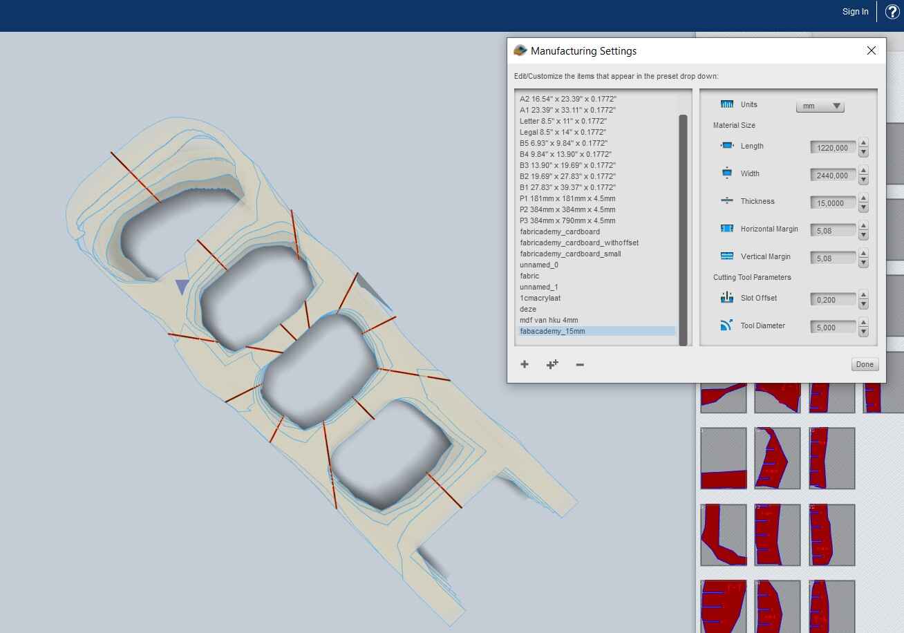
I tried a couple of slicing methods, but they all looked pretty disappointing.
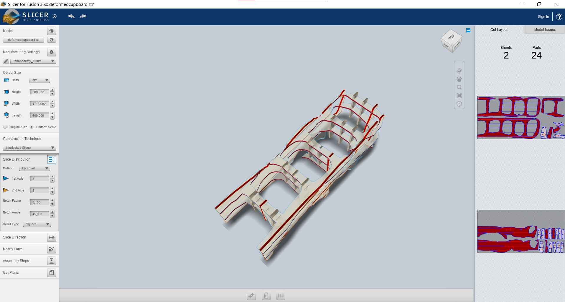
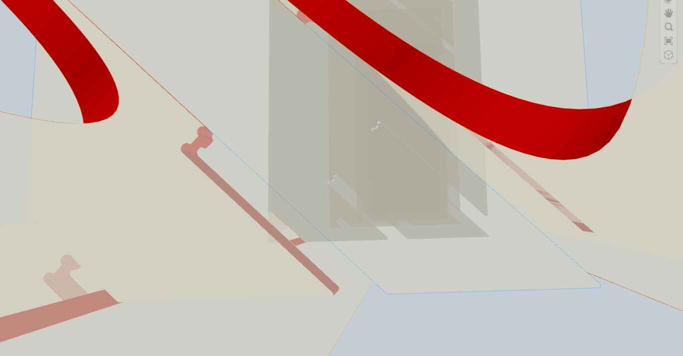
I then tried slicing the model I originally exported from Fusion in Slicer, which worked way better. I tried a curved design with some deleted vertical layers in the middle and strategically places horizontal layers that could function as shelves.
I tried some other settings too:

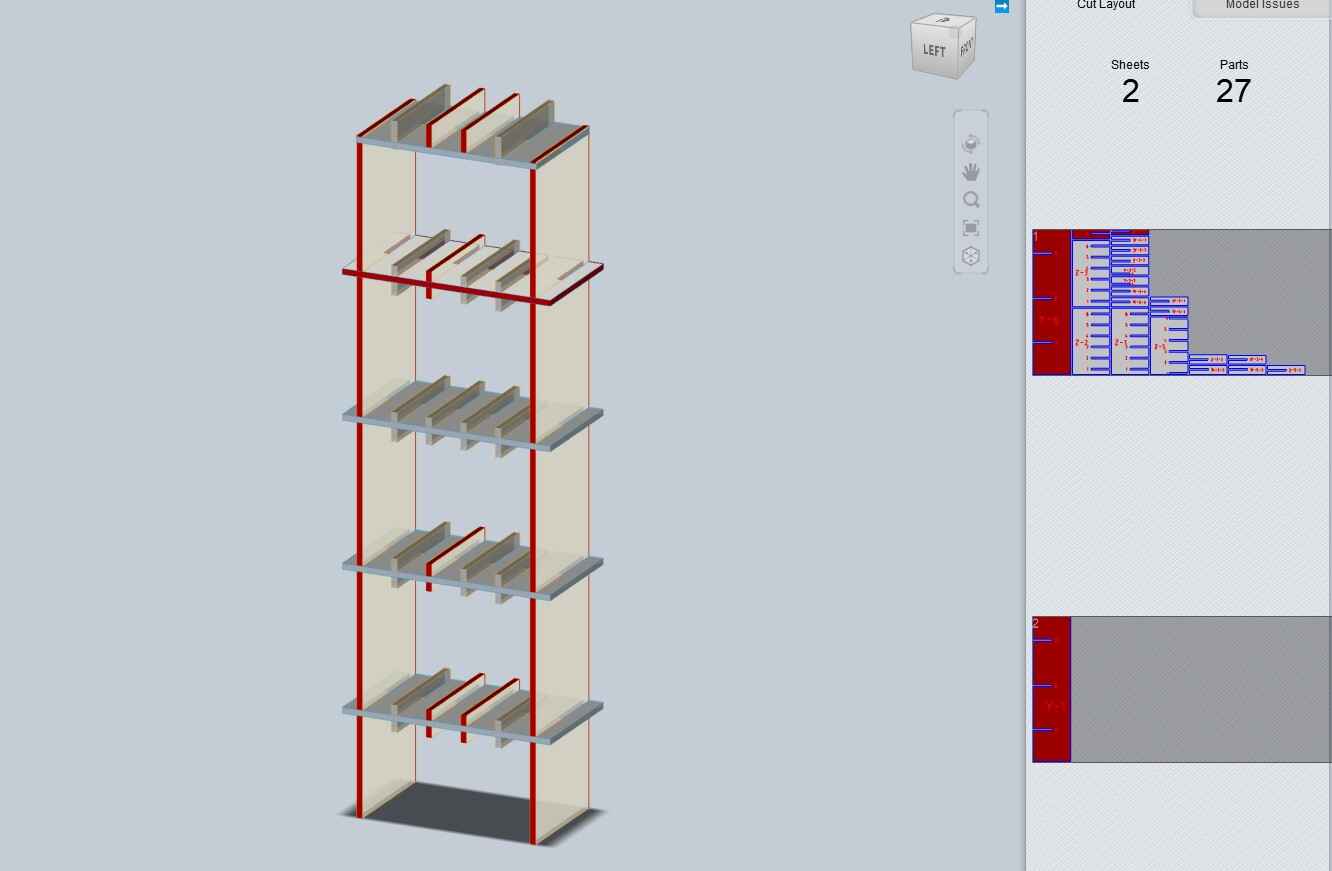

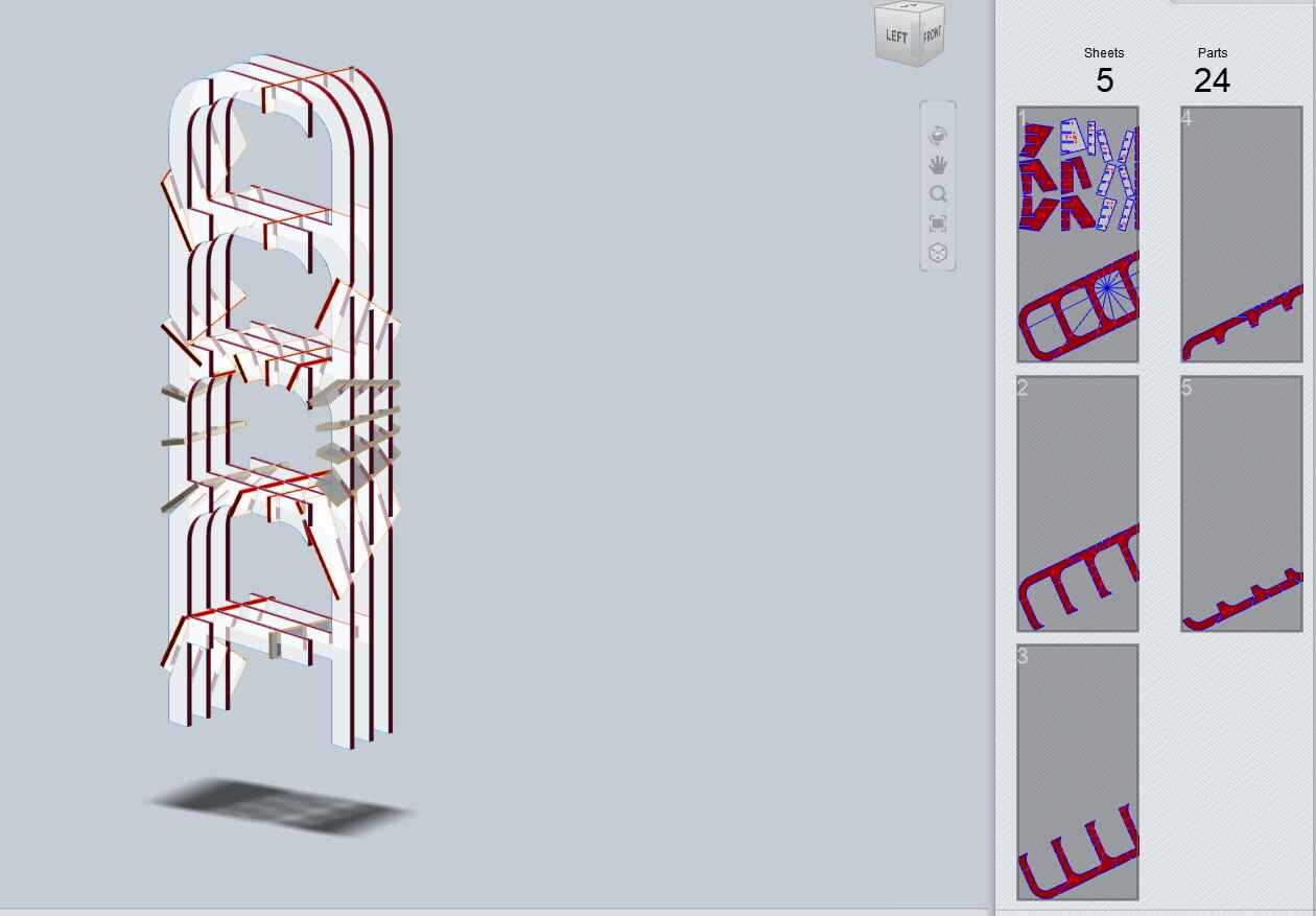
I also tried making it thinner, but I forgot to take the thickness of the shelves into account and the whole thing looked like it would fall apart as soon as you would breathe into its general direction.

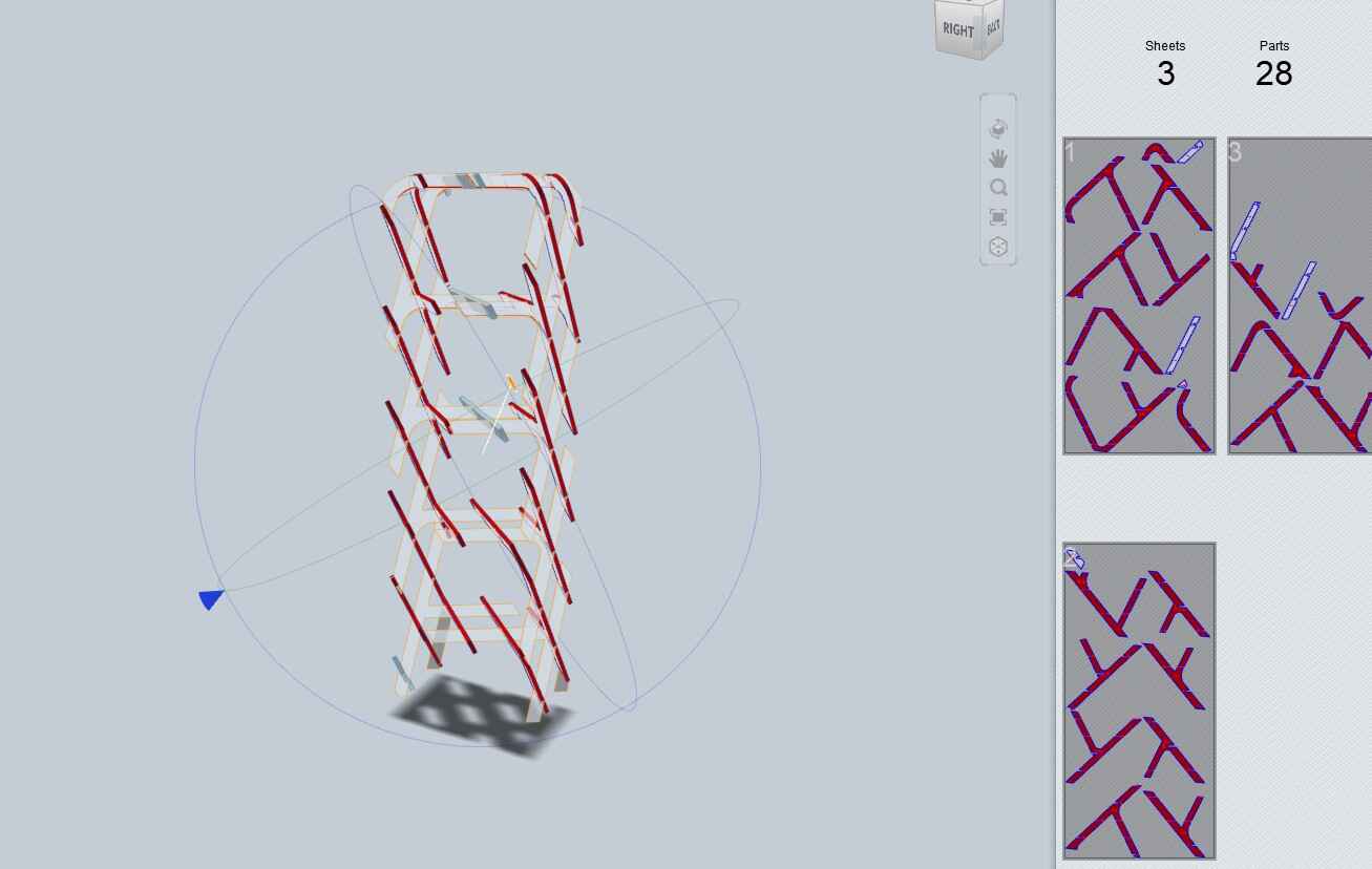
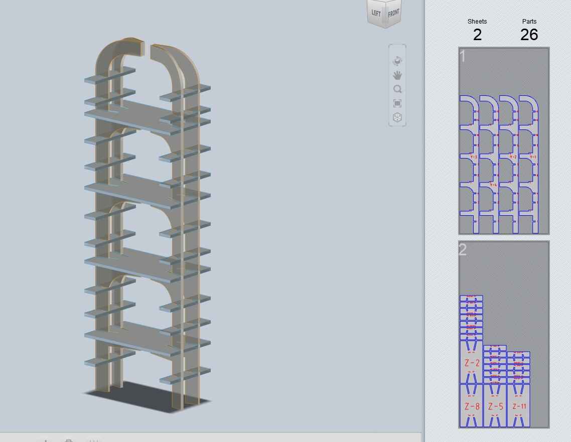
Then I tried a completely different design for a change, because I wasn’t sure whether I liked it.

I liked the design in Fusion, but as a sliced cupboard it kind of lost its charm. It also really isn’t useful as a bookcase anymore; I figured I could use it for clothing instead but I wasn’t too convinced, so I went back to my previous design.
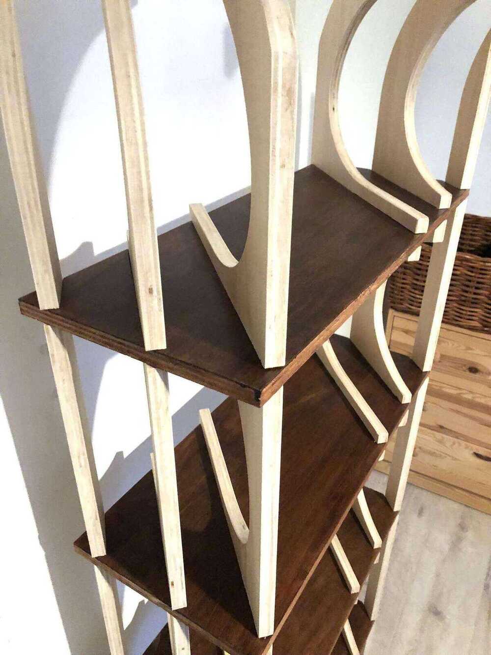
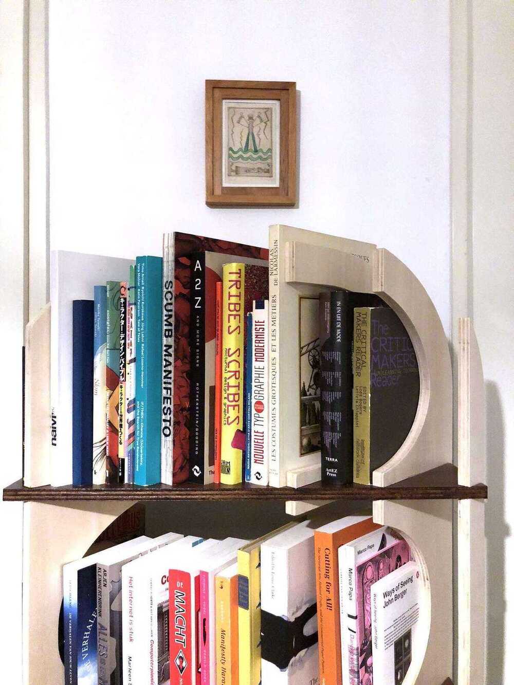
At some point I had to accept that the bookcase couldn’t be almost two meters tall, fit on a 1,22m x 2,44m piece of plywood and look somewhat interesting. I decided that a bookcase that was more my height, so around 1,6m, would also be charming. I also liked the first design the most: the one with the angled vertical pieces and the deleted middle parts. I thought it would be an fun way of presenting books: giving them more depth by not just showing the spine but also seducing the reader with a sneak peek of the cover. The bookcase has some spots on each shelf on both sides for more books. I did think that it would be more convenient if the bottom part of each shelf would be curved too, because then the books would be more stable. I changed some parameters in Fusion and exported as an STL again, then imported into Slicer and replicated the steps I took to get the first design.

Relief Type: Vertical selected here (the diameter of the fillet is determined by the cutting tool parameters in the manufacturing settings); this hides the fillet completely.
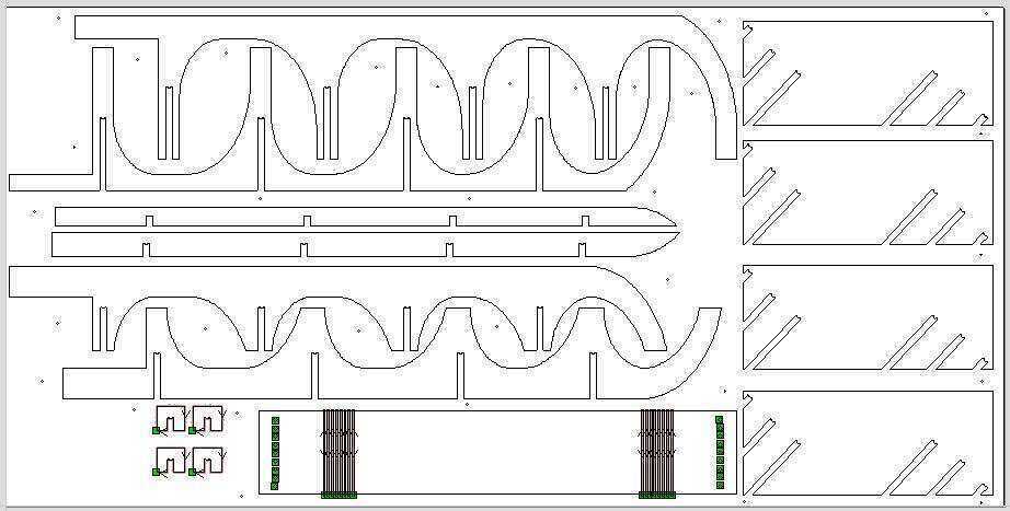
Then I exported it as a PDF (DXF leaves all of the lines open, while PDF closes them nicely). Since there weren’t many parts, I did the nesting manually in Illustrator. This is what the imported PDF looked like:

Fully nested I managed to get all of the parts easily onto one sheet of 1,22m by 2,44m. Since I had quite some space left over I decided to draw a quick shoerack with a flexure and some holes to weave through.
Extruded to turn it into an easy-to-export drawing:

VCarve Pro
Before you start in VCarve, you should know the dimensions of your material. Measure the thickness in various spots.
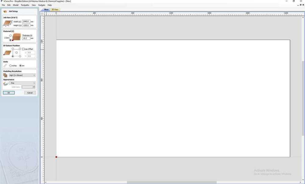
Job Setup
Specify the size of the material (Job Size X & Y). The maximum size for this shopbot is 1,22m (Y) by 2,44m (X). Zero at the bottom of the material unless you have a reason to zero at the top. Appearance and resolution only affect the rendering so it doesn’t really matter.
File import & preparation
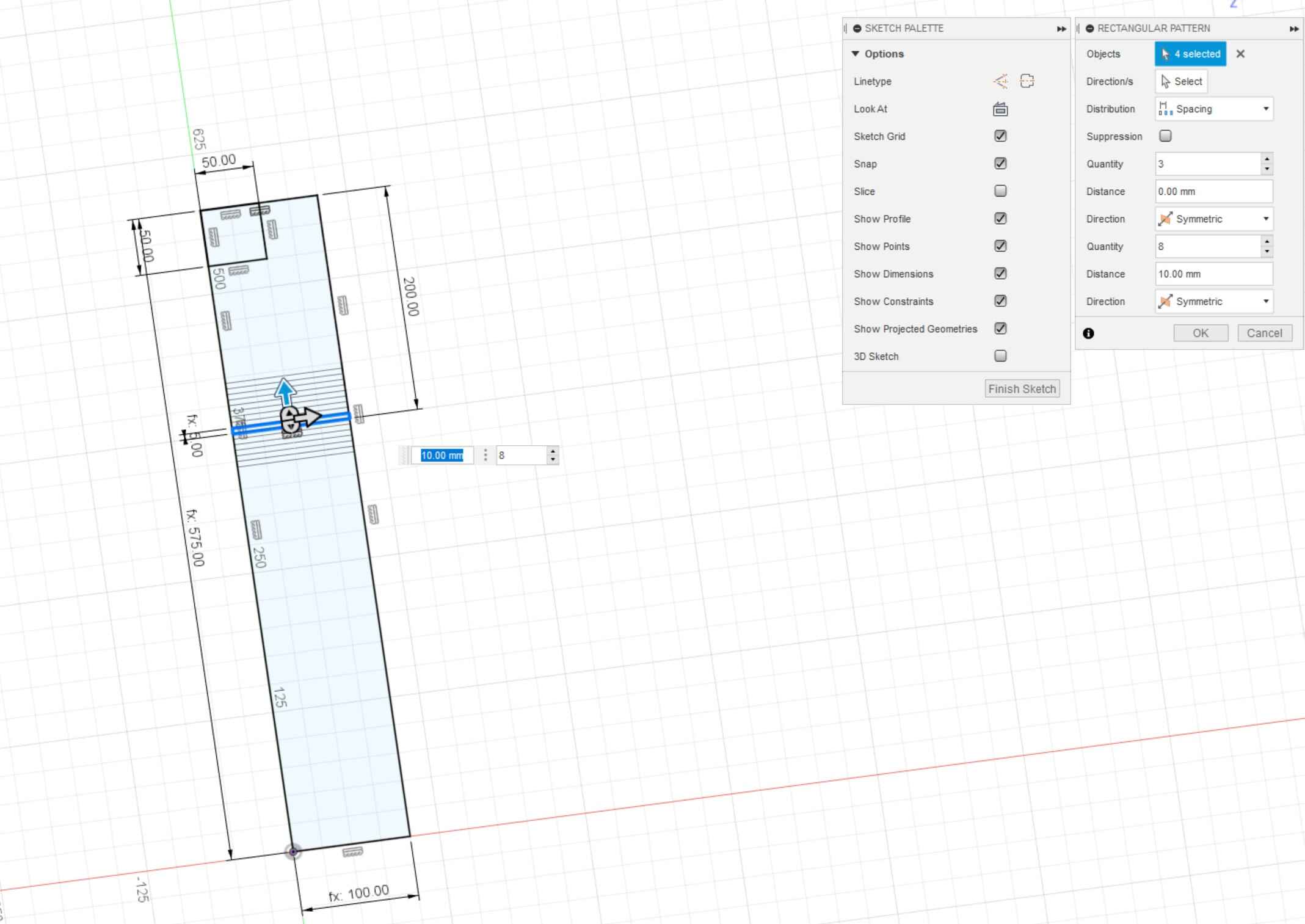
I added circles with a diameter of 5mm where I wanted to place my screwholes. Then click the Toolpath menu on the right; with the pushpin you can stop it from hiding automatically. I also added two press-fit test pieces to mill first.
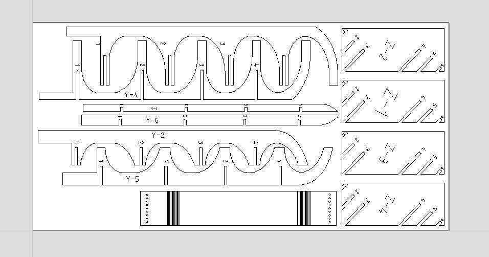
Since I exported from Slicer my file also has numbers for where each part goes. I ignored them when I improved my nesting in VCarve.
Fillets
When milling you have to keep in mind that a mill is round and has a diameter that is not negligle. To make angular parts fit, you need some extra space on inside corners. You can do this in your file beforehand or directly in Vcarve. Options in Vcarve:
- Normal
- Dog-bone
- T-bone
Here a T-bone on the left and a dog-bone on the right; normal means that there is no fillet.

You can add fillets in VCarve; I used dogbone fillets to make sure my milled parts would fit together, but I added these in Slicer already so I wouldn’t have to click all of the corners and risk missing one.
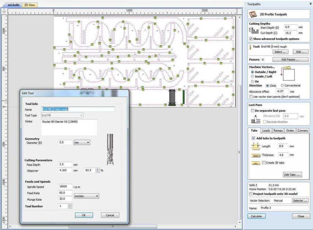
Toolpaths
Drilling toolpaths
I started with the drilling toolpath by selecting all the circles I drew in the previous step and selecting the mill I wanted to use from the tool database. I used a 5mm two flute endmill. I exported this toolpath and milled it, then secured the plywood to the sacrificial layers with woodies.

Then I made the 2D profile toolpaths for my press-fit test, milled it and tried it out. It fit, but it was a tight fit, so I made a new test with a new allowance of -0,07mm which was a more comfortable fit.

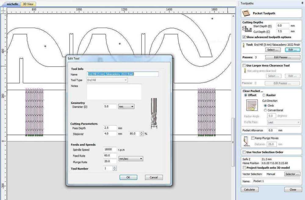
Pocket toolpaths
- Offset: nicer for rounder shapes usually
- Raster: nicer for angular shapes
- Pocket allowance: for pressfit purposes you can move a bit inward or outward
- Profile pass: last means that the machine mills the outer line last to get a smoother surface.
The start depth (D) is the top of the material unless you are milling in a pocket. Cut depth (C) is the depth you want your pocket to have (relative to the start depth). For example: first pocket is 3mm deep, and the second pocket within this pocket is 2mm deep, then the start depth for the second pocket is 3mm and cut depth 2mm, a total of 5mm deep. Clear pocket in a raster or offset (see image).
I made pocket toolpaths for the flexures. I didn’t make a test cut for this, which I came to regret later because 7.5mm was not deep enough.
Profile toolpaths
Inside, outside & on; always check in the preview if the milling bit is going where you want it to go.
Then I made the cut-outs for the holes that I wanted to weave through on the shoerack. The diameter of these holes are 10mm, so with a 5mm end mill there is no leftover material so no tabs needed.
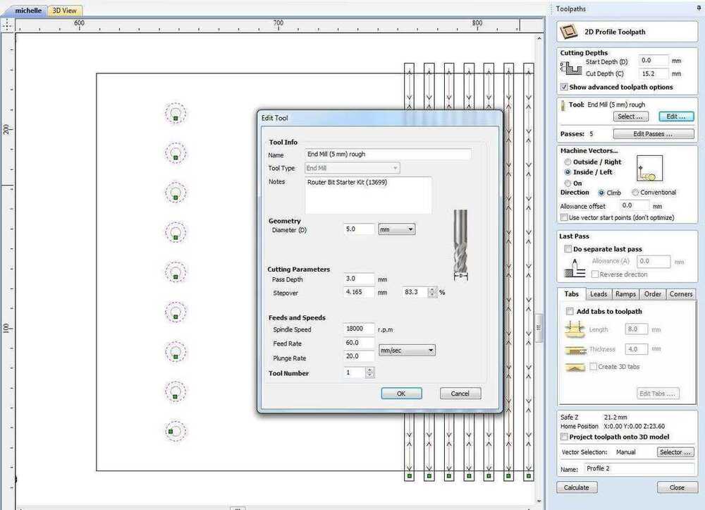
With the new allowance offset determined, I calculated the rest of my toolpaths for which the allowance was needed. I added plenty of tabs: these will make sure the material doesn’t start moving around once it’s almost cut out. You can start by filling in values and then click add tabs, but you can also use the mouse to add, remove and move tabs.
Here you can see all of the toolpaths in the 3D preview:
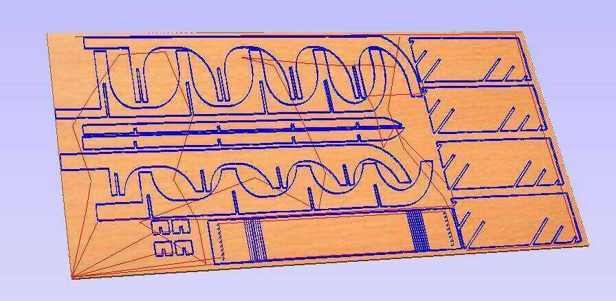
Every time you change something you have to recalculate the toolpaths.
CNC

Milling
I started with the drilling toolpath for this week’s assignment.
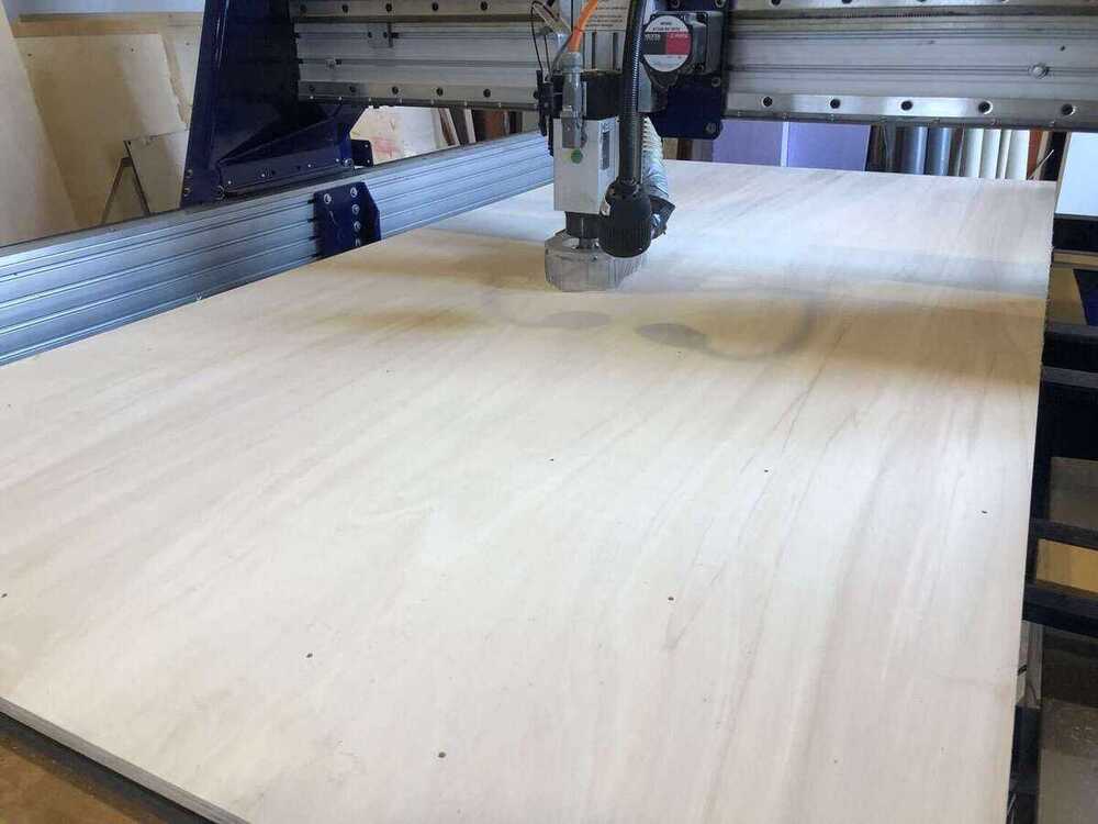
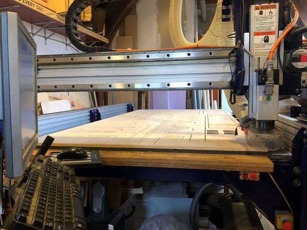
After that I secured the wood to the sacrificial layer with woodies. I should have moved my wood a few millimeters from the side of the sacrificial layer, because there is a part where this layer is about a millimeter higher. This can function as an alignment ridge, but I went a little bit over it, which made it harder to get the material flat on the bed. I couldn’t move the material because I had already made the drillholes and I didn’t want to risk moving the wood too much.
Then I ran a first joint test. I didn’t put any allowance in Vcarve there.
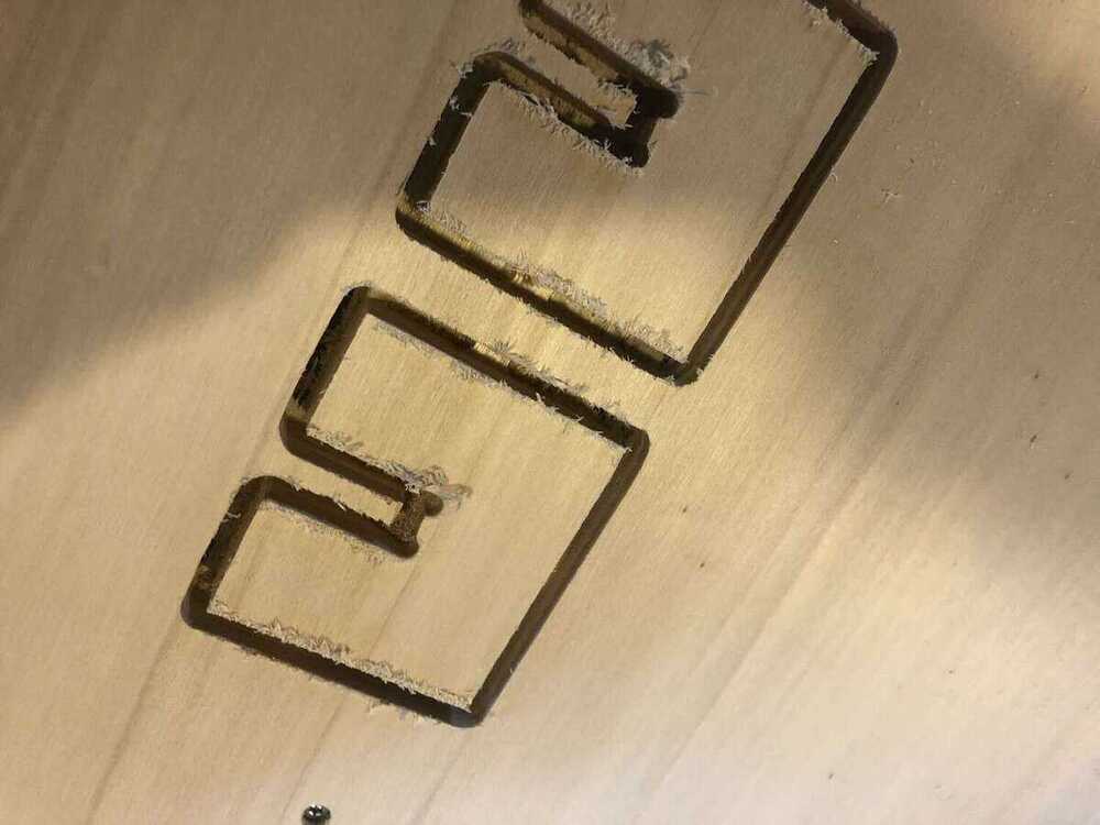
I had leveled the Z axis on the bed, but as you can see here it didn’t go all the way through the plywood in this corner of the material. The sacrificial layer isn’t perfectly flat, so I thought if it’s only this corner I don’t have to relevel the Z axis; I couldn’t do that anyway because I had the entire bed covered with my plywood fixed in place.
After some sanding it was a pretty good fit, but I thought it was a little too press-fit, so I made a new test with an allowance of -0.07mm. I liked this fit better, so I used this allowance for all of the other cutting toolpaths.
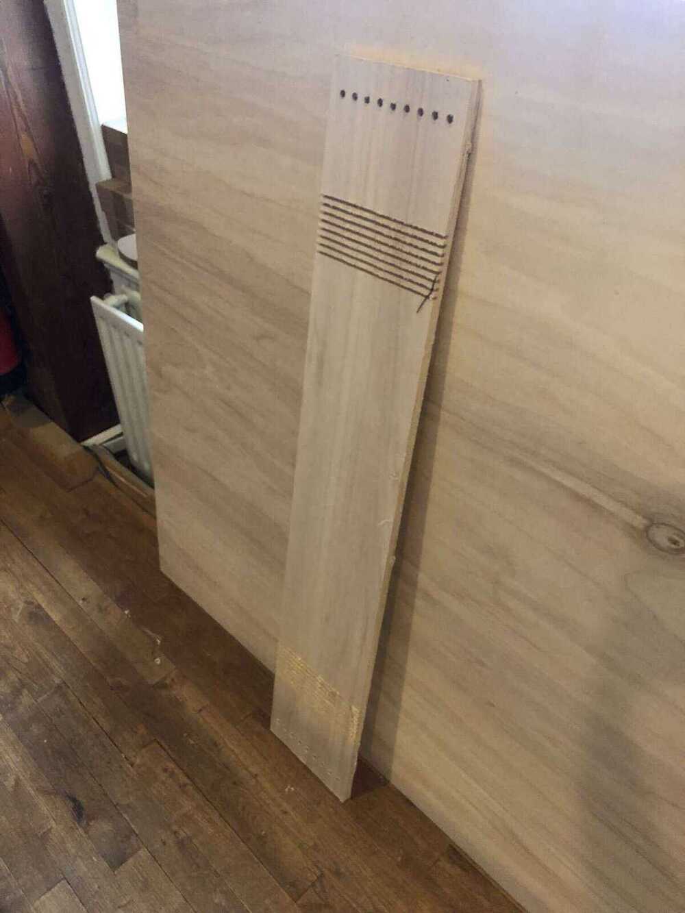
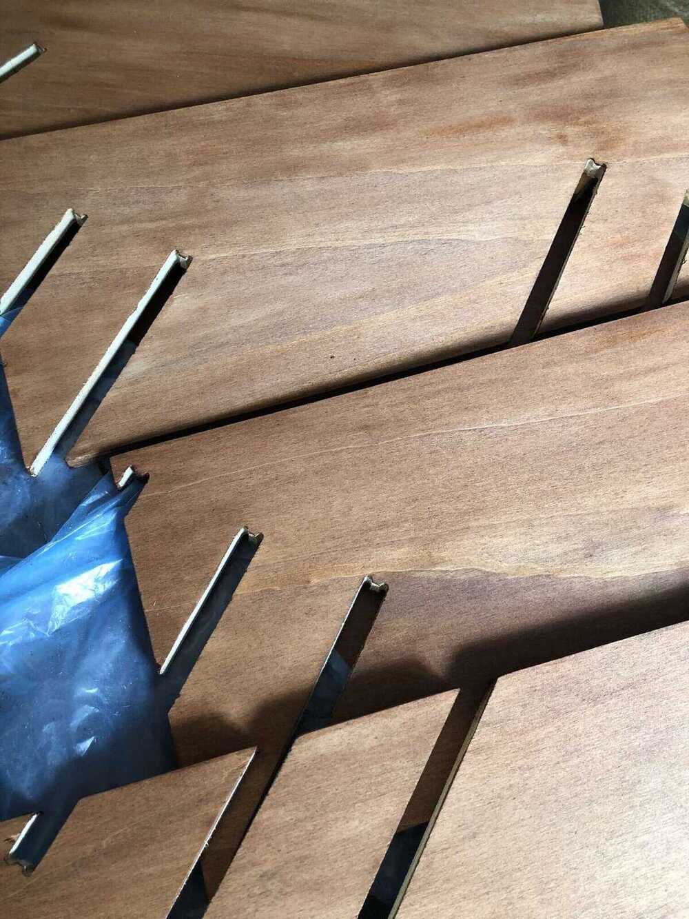
Then it was time to start the actual file. The first toolpaths were the slots for bending the wood for the shoe rack. I took the tool diameter into account, but I didn’t consider that the 5mm wide parts in between the slots would receive the full power of the spinning milling bit too. You can see that parts of the top layers chipped off.
The total job took about 1h40 which was faster than I thought. I didn’t notice that VCarve had a scale factor applied to the time estimate so I thought it was going to take an hour longer.
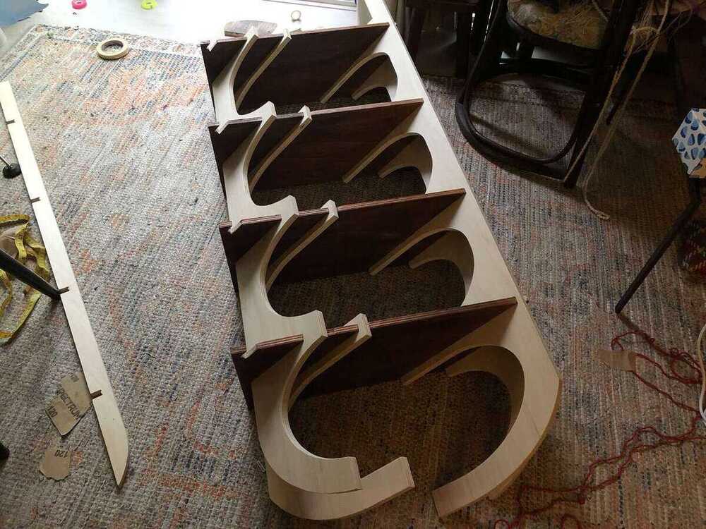
The milled pieces:


I tried the usual hammer and chisel to get rid of the tabs first (with a piece of leftover wood between the chisel and the sacrificial layer), but it had a high rate of chipping the plywood so I switched to sawing. Sawing from the back works best because you can push against the tab.

Sanding
Next came my least favorite part: sanding. I spent about 4 hours sanding at Waag, first with 80 grit and then with 120 grit. It would have been even better to continue sanding, but I was the only one left in the building on a Friday night and I wanted to go home.

All packed up against possible snow:

Painting
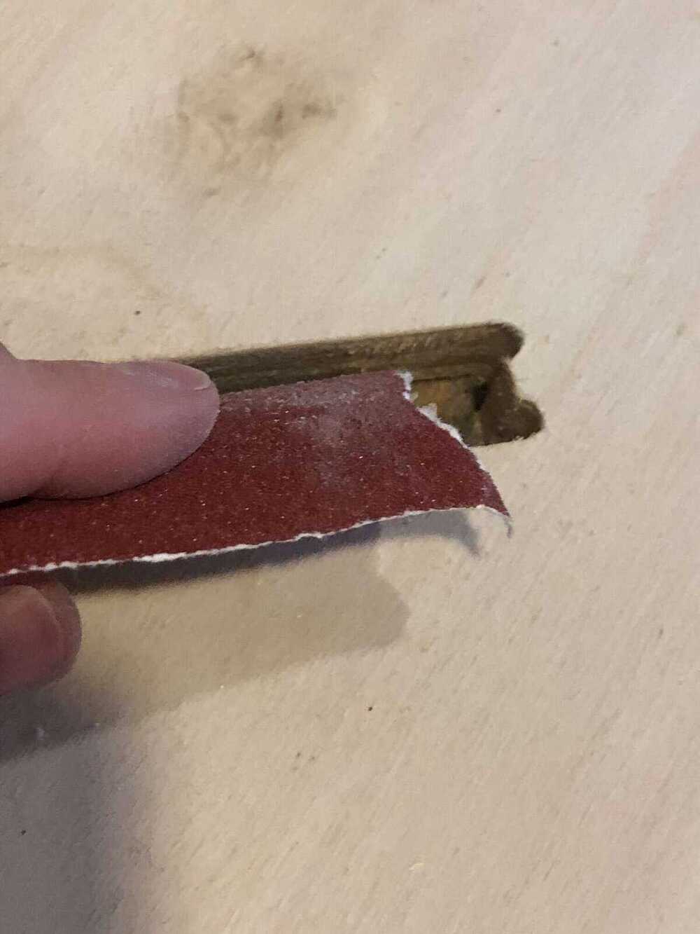
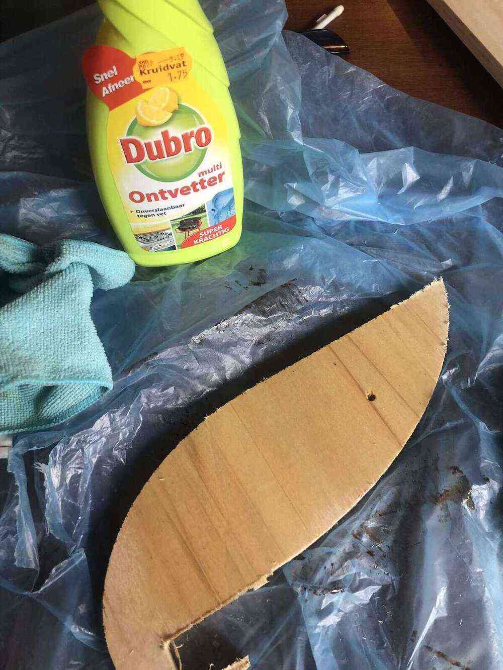
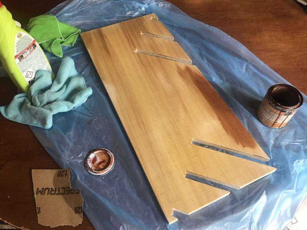
The next day I started with some tests on leftover plywood from milling with the interior lacquer that I still had in my cupboard for my dining table. I thought it was wood stain but I was wrong. I still wanted to use it because I liked the color. I sanded the top of the wood lightly with 120 grit and wiped the dust with a microfiber cloth. The first test on the top left is where I put too much paint and I didn’t mix it well enough. On the bottom I did a lighter coat. On the second picture I used a microfiber cloth to wipe off excess paint.


I also tried degreasing the wood with a regular spray degreaser for kitchen purposes (probably not the best but all that I had). I liked this result the most so I went with the method of sanding - wiping away dust - degreasing spray - wiping.
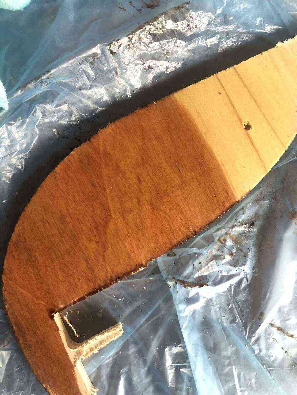
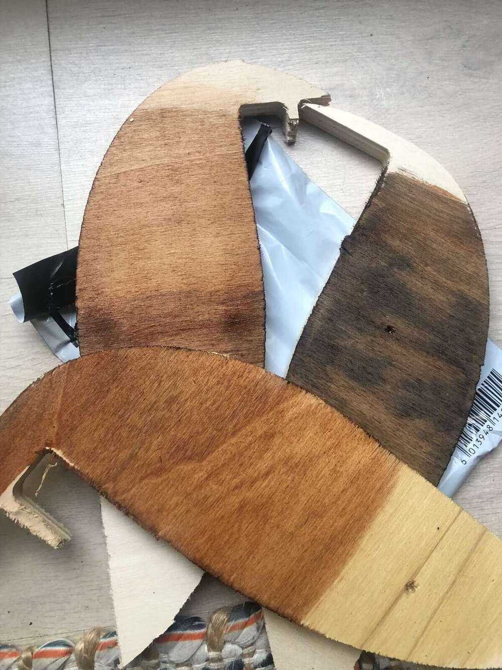
After a first layer of this paint it looked pretty patchy. I had seen on a Youtube video that before staining wood you need to prep it with a preconditioner so you get a more even tone, but I didn’t have it and I also didn’t have time to order and wait for it (nor did I want to spend 20 euros on it). I hoped a second layer of paint would fix it.
While the paint was drying I went to the shop to get a transparent semi-shiny varnish to use as a top coat (and the sanding block below). I sanded the painted surfaces lightly with grit 120 and tried applying a second coat of paint with this roller, but it was really ugly so I quickly switched to the extra wide acrylic brush I had also bought.


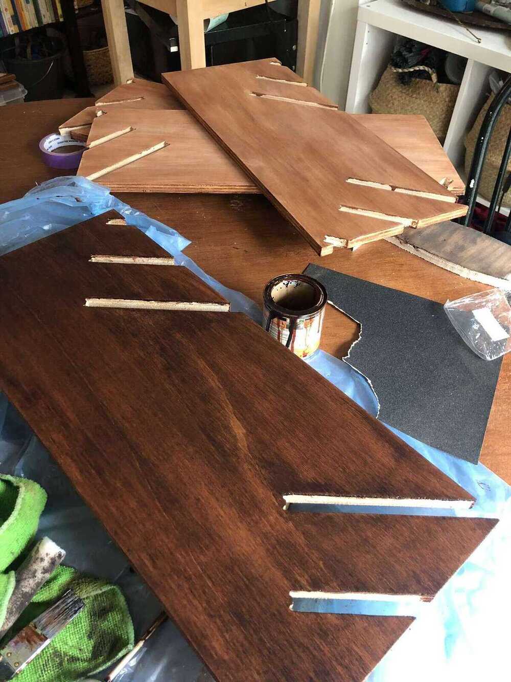
While the paint was drying, I sanded all of the unpainted vertical parts lightly with 120 grit and gave them a transparent varnish. Initially I had planned to paint the entire bookcase but I quickly realized I barely had enough paint to cover the tops of the shelves, and I wanted to have some spare paint for my tabletop. When the paint was dry I also coated those in the same varnish.

After all of the parts were dry, I tried to assemble the cupboard. At this point I realized that I had not taken the extra friction that the paint and varnish caused into account. I also didn’t sand very well on the insides of the joints. I also did not think about the fact that even though a short joint worked fine, I had some pretty long joints and I also needed to attach each vertical part to four shelves simultaneously. The -0,07mm machining allowance was not enough to comfortably assemble the cupboard. With some force I could make it press-fit, but I didn’t think that it would be a good idea to use so much force all around.
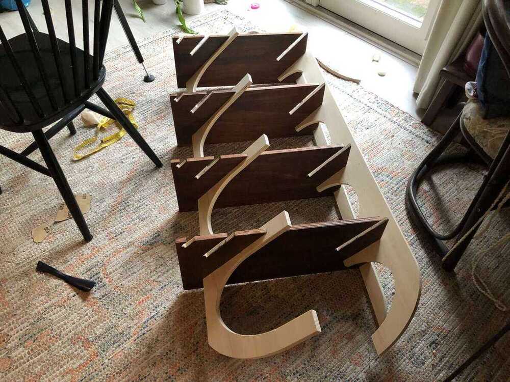
I went for another round of sanding manually, but I wasn’t very happy doing this so I grabbed my Dremel. I was very lucky to find out that the diameter of the sanding cylinder that I had fit into the slots that I had. The biggest struggle was keeping the sanding cylinder in place, but after replacing it with a new one it didn’t move around anymore (it was really going everywhere).


Finally it could be assembled.
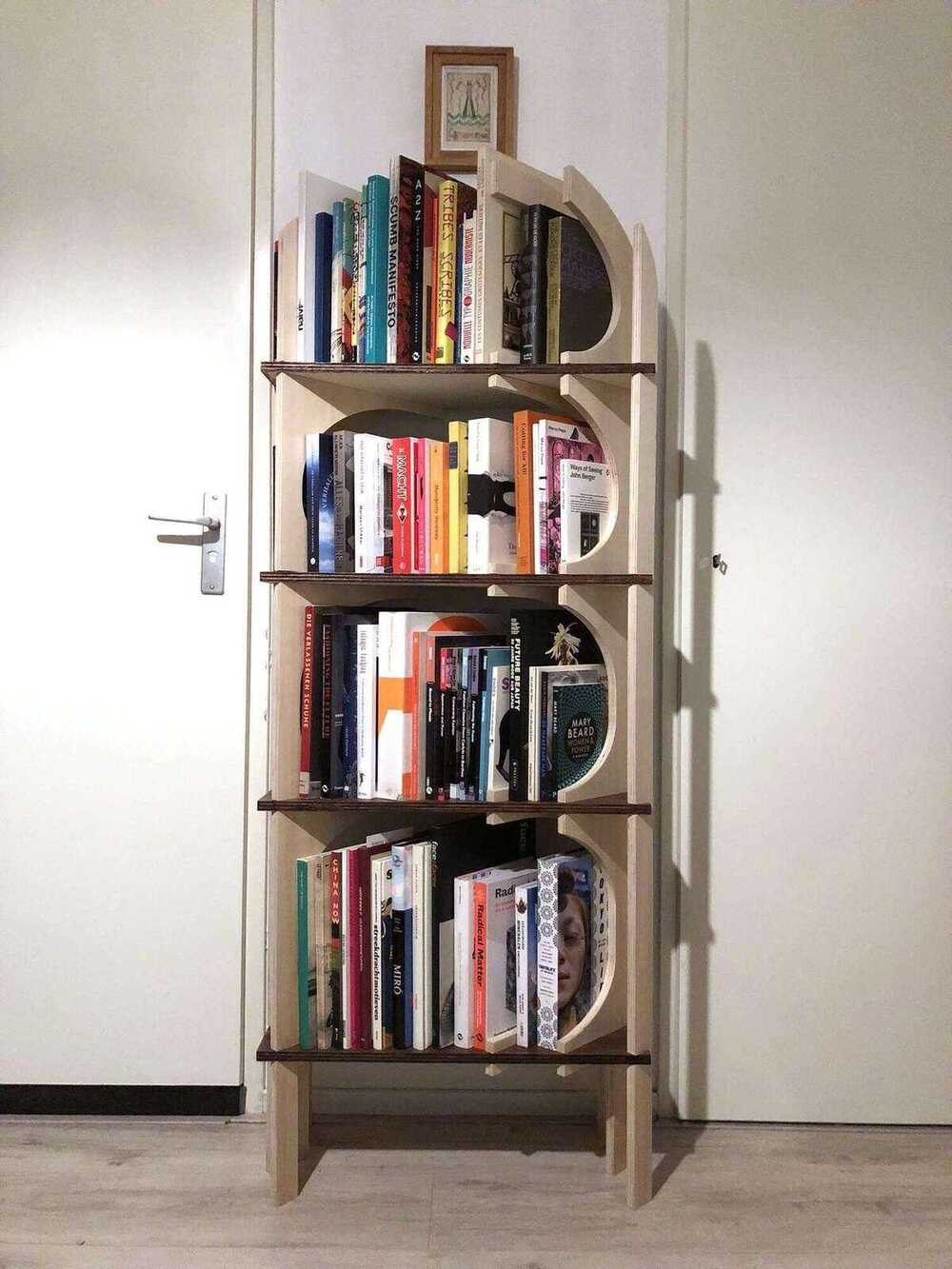
Result
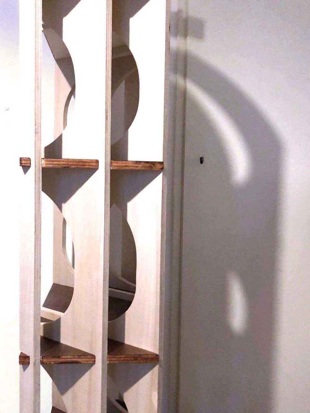
The resulting bookcase in its new spot before I painted the sides of the shelves again:
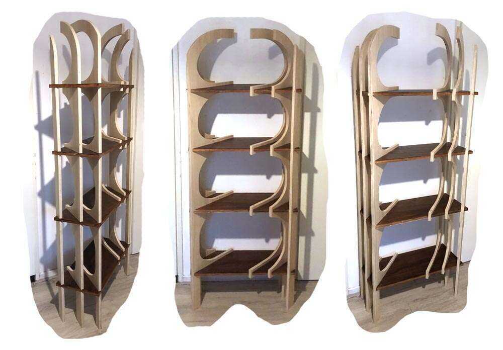
It has plenty of space for extra books.
Some of the imperfections on the sides of the plywood I fixed with wood filler that I then painted over when I gave the sides of the shelves another careful coat of paint.

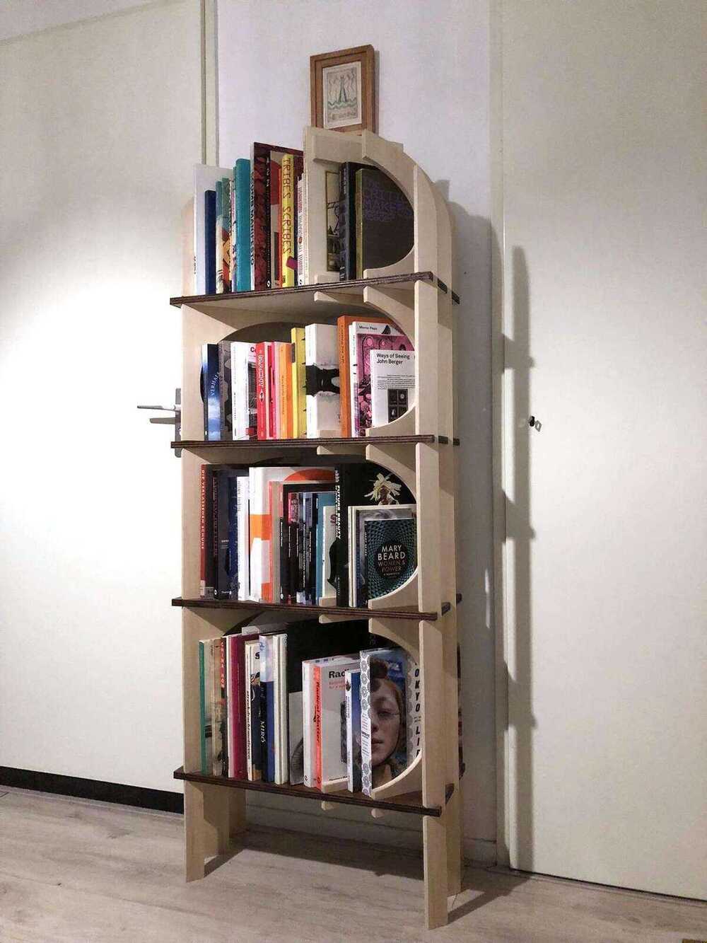
Filled with books it looks pretty nice:
Reflection
I found this a very fulfilling week. I read a book on craft and technology last weekend and while sanding and painting I had a lot of time to reflect on it. The problem with reflecting while doing something is that it’s not the same as documenting it. I planned to be done by Sunday night with the bookcase plus documentation, but I finished the last coat of lacquer at 22:00 on Sunday and the documentation on Tuesday night.
Things that went wrong
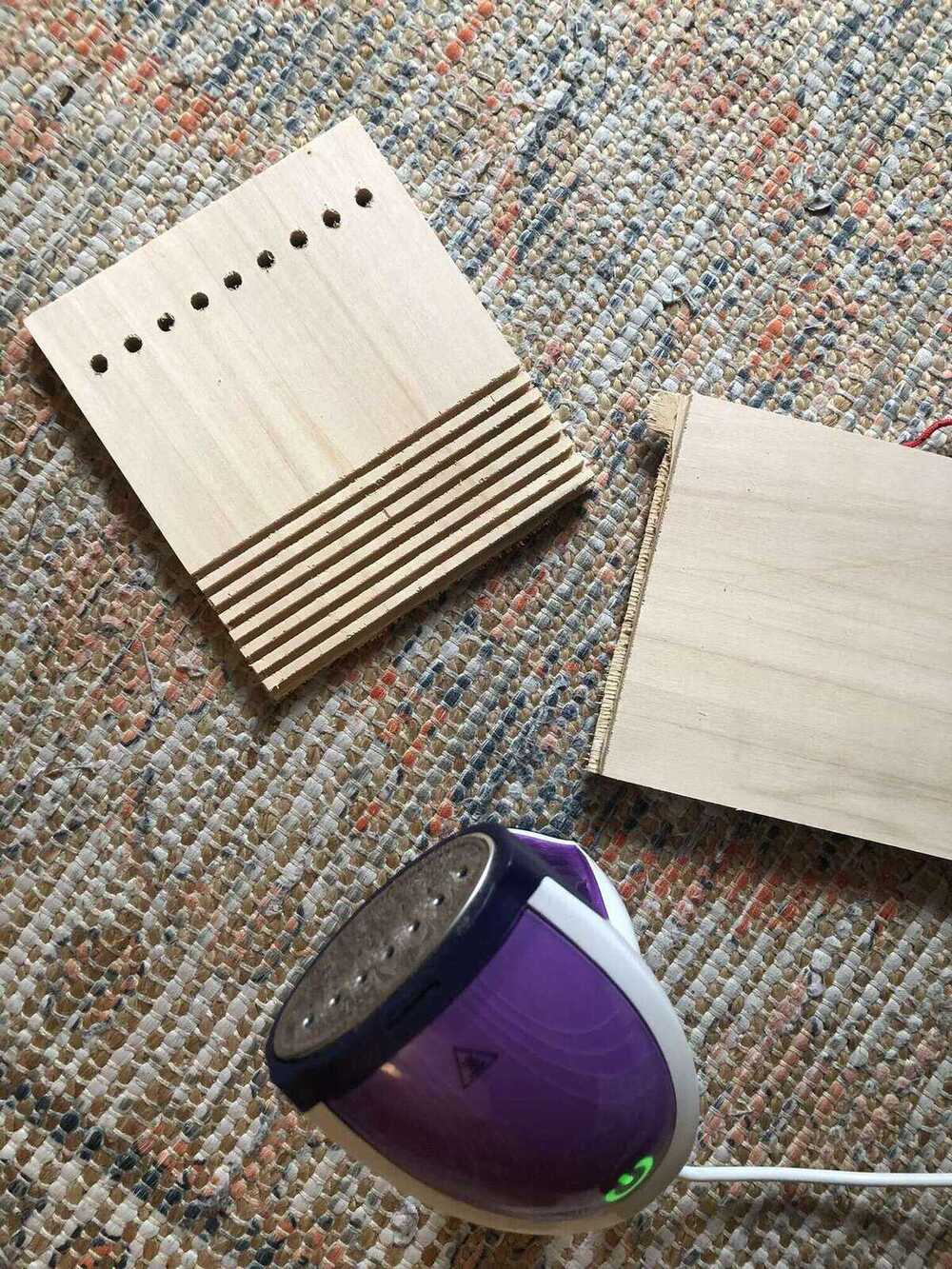
Flexure failure
I also tried to steam the flexure of the shoerack, but I failed miserably because I didn’t mill deep enough. Since I was first to mill and I was in a hurry, I didn’t do proper research into what the depth of the cut for the flexure should be. I could have seen it easily in the image that Neil showed during the lecture, but I wasn’t thinking straight.
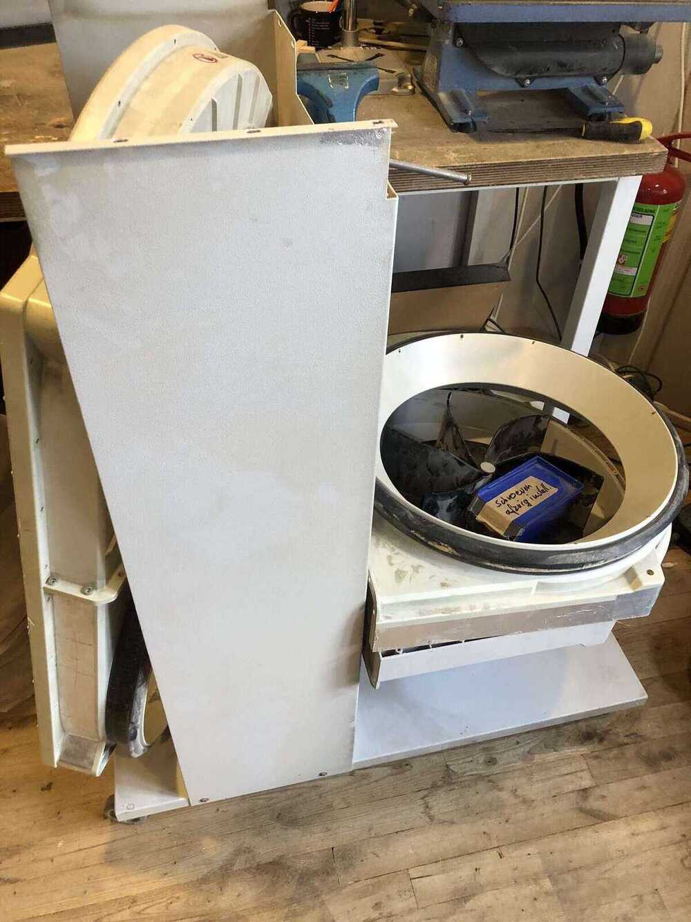
Dust collector failure
Up until Monday morning, the dust collector was doing just fine. However on Monday morning while Pieter was milling, it died after 15 years of service. I’ve been very lucky that I had no issues milling on the Friday before, but Pieter and Samson weren’t as lucky. Currently Henk and Saco are looking for a replacement part.


Files
CNC theory notes
Saco gave us a tutorial on how to use the CNC and on the theory behind it.
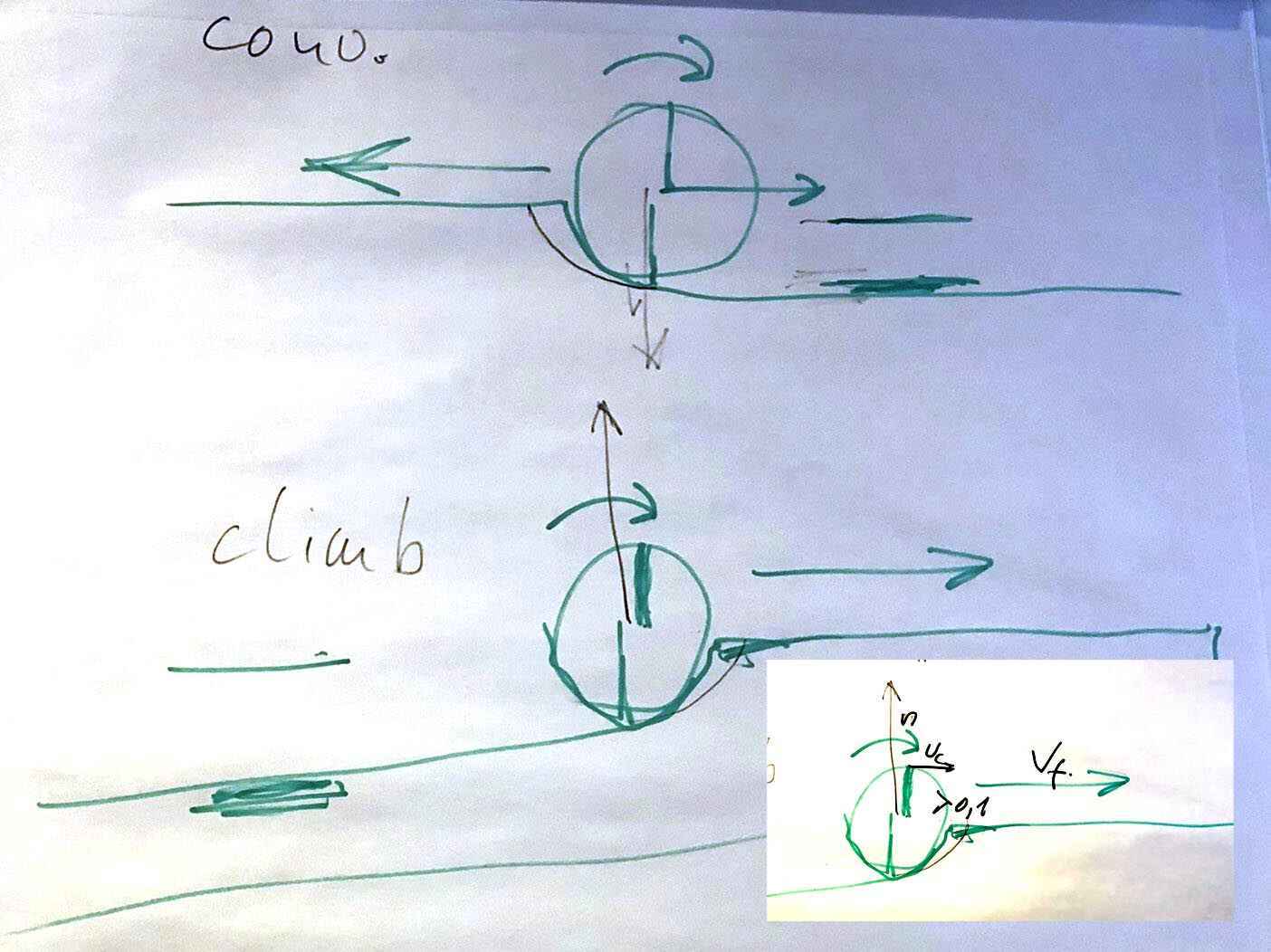
Here are some notes on the confusing relationship between the amount of flutes (the cutting sides of a milling bit) and feed rates:
- The more flutes, the higher the feed rate can be because the drain is faster with more flutes
- With a 1 flute end mill you go slower, with several flutes you go faster so that the chip is thick enough.
- However, with more flutes the chip removal is more difficult, so with a four flute you go faster but less deep
- A 1 flute mill has more space to get rid of chip load so you can go faster
- If the chip load is too small then the mill can’t cut enough and then you get more friction, and that’s bad for the milling bit because it wears out faster
The milling bits that we have in the lab are angled to deal with the chip load, so they can drill straight down into the material.
Conventional vs climb: we always use climb because with conventional you have the risk that the milling bit spins itself loose. When you have a manually operated CNC you always use conventional because the machine becomes way harder to operate when using climb.